Table of Contents
Advertisement
Quick Links
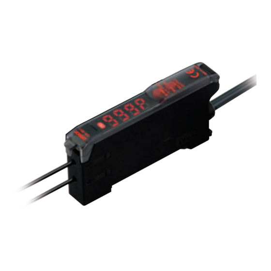
Simple Fiber Amplifier
E3X-SD
The Standard for Fiber Amplifiers with
Simple Operation and High Performance
■ Operation so simple that essentially anyone can use the
amplifier right way.
■ Immediately determine operation and amount of light with a
simple, bright display.
■ General-purpose capabilities to simply handle a broad range of
applications.
Ordering Information
Amplifier Units
Digital Display and Direct Key Setting
Connection
Item
Appearance
Standard
models
Pre-wired
Wire-saving
connector
Combining Amplifier Units and
Connectors
(Basically, Amplifier Units and Connectors are sold
separately)
Refer to the following tables when placing an order.
Sensor I/O Connectors (Order Separately)
Size
Cable specifications
M8
Standard cable
Accessories (Order Separately)
Mounting Brackets
Appearance
Applicable models
E3X-SD@
Ratings and
NPN
method
Specifications
output
E3X-SD11 E3X-SD41
---
E3X-SD6 E3X-SD8
Amplifier Units
Type
Standard
E3X-SD6
models
When Using 5 Amplifier Units
5 Amplifier Units
Appearance
Straight
connector
L-shaped
connector
Model
E39-L143
Amplifier Unit Connectors (Order Separately)
Note: Stickers for Connectors are included as accessories.
Model
Item
PNP
output
Master
Connector
Slave
Connector
Applicable Connectors (Order Separately)
+
NPN
PNP
E3X-SD8
+
Cable type
2 m
Four-
5 m
conductor
2 m
cable
5 m
Quantity
1
Appear-
Cable
No. of
ance
length
conductors
3
2 m
1
Master Connector
Slave Connector
E3X-CN11 (3-wire)
E3X-CN12 (1-wire)
1 Master Connector + 4 Slave Connectors
Model
XS3F-M421-402-A
XS3F-M421-405-A
XS3F-M422-402-A
XS3F-M422-405-A
End Plate
Appearance
Model
PFP-M
Model
E3X-CN11
E3X-CN12
Quantity
1
1
Advertisement
Table of Contents

Related Manuals for Omron E3X-CN11


Summary of Contents for Omron E3X-CN11
- Page 1 Type Master Connector Slave Connector (Basically, Amplifier Units and Connectors are sold Standard E3X-SD6 E3X-SD8 E3X-CN11 (3-wire) E3X-CN12 (1-wire) separately) models Refer to the following tables when placing an order. When Using 5 Amplifier Units 5 Amplifier Units 1 Master Connector + 4 Slave Connectors...
-
Page 2: Ratings And Specifications
Polycarbonate Accessories Instruction manual * Models with connectors have a dielectric strength of 500 VAC. Amplifier Unit Connectors Item Model E3X-CN11 Rated current 2.5 A Rated voltage 50 V 20 mΩ max. (20 mVDC max., 100 mA max.) Contact resistance (The above figure is for connection to the Amplifier Unit and the adjacent Connector. - Page 3 E3X-SD Fiber Unit Overview No snagging, no breaking: Right-angle (L-shaped) Models New Head Shape Feature L-shaped Attachment Feature Reflective model, 90 mm M6 screw E32-D11N 10 mm* 280 mm No snagging during maintenance. Fiber flexibility prevents breaking. Through-beam model, M4 screw E32-T11N 8 mm* Convenient design...
- Page 4 E3X-SD Sensing Distance Through-beam Models (Unit: mm) Model E3X-SD@ Type Standard models E32-T11R/E32-T12R/E32-T15XR/E32-TC200BR (B4R) E32-T14LR/E32-T15YR/E32-T15ZR Flexible E32-T21R/E32-T22R/E32-T222R/E32-T25XR/ (new standard) E32-TC200FR (F4R) E32-T24R/E32-T25YR/E32-T25ZR E32-TC200/E32-T12/E32-T15X/E32-TC200B (B4) E32-T14L/E32-T15Y/E32-T15Z Standard models Standard E32-TC200A E32-TC200E/E32-T22/E32-T222/E32-T25X/E32-TC200F (F4) E32-T24/E32-T25Y/E32-T25Z E32-T11/E32-T12B/E32-T15XB Break resistant E32-T21/E32-T221B/E32-T22B E32-T25XB Fluorine coating E32-T11U E32-T17L 14000 E32-TC200 + E39-F1...
- Page 5 E3X-SD Reflective Models (Unit: mm) Model E3X-SD@ Type Standard models E32-D11R/E32-D12R/E32-D15XR/E32-DC200BR (B4R) E32-D14LR E32-D15YR/E32-D15ZR Flexible E32-D211R/E32-D21R/E32-D22R/E32-D25XR/ (new standard) E32-DC200FR (F4R) E32-D24R E32-D25YR/E32-D25ZR E32-DC200/E32-D15X/E32-DC200B (B4) E32-D12 E32-D14L Standard models E32-D15Y/E32-D15Z Standard E32-D211/E32-DC200E/E32-D22/E32-D25X/ E32-DC200F (F4) E32-D24 E32-D25Y/E32-D25Z E32-D11/E32-D15XB E32-D21B/E32-D221B Break resistant E32-D21/E32-D22B E32-D25XB Fluorine coating E32-D11U...
-
Page 6: I/O Circuit Diagrams
E3X-SD I/O Circuit Diagrams Output Output Operation Model transistor Timing charts Output circuit form selector operation mode Incident light No incident light Operation Brown indicator Operation indicator (orange) LIGHT ON (orange) Light-ON (L-ON) Load Output Photo- transistor Black electric 12 to Sensor Operate Load... -
Page 7: Safety Precautions
E3X-SD Nomenclature Amplifier Units E3X-SD@ Operation Keys Sensitivity adjustment (UP/DOWN or teaching) Operation Selector Use to switch between Operation Indicator Light-ON and Dark-ON Timer switch Incident level Lock lever OFF/D: OFF-delay timer indicators ON/D: ON-delay timer OFF: Timer function is OFF. TEACH/RUN Mode Selector Used to select TEACH or RUN mode. -
Page 8: Precautions For Correct Use
E3X-SD Precautions for Correct Use Do not use the product in atmospheres or environments that Fiber Connection and Disconnection exceed product ratings. The E3X Amplifier Unit has a lock lever. Connect or disconnect the fibers to or from the E3X Amplifier Unit using Amplifier Units the following procedures: ●... - Page 9 Connector and remove it. (Do not attempt to remove Connectors without separating them from other 2. Remove the clip by rotating the Amplifier Unit. Amplifier Units first.) Press down Rotate Lever Remove Pull Strengths for Connectors (Including Cables) E3X-CN11: 30 N max. E3X-CN12: 12 N max.
- Page 10 E3X-SD Dimensions (Unit: mm) Amplifier Units Amplifier Units with Cables E3X-SD11 Vinyl-insulated round cable E3X-SD41 4 dia. cable / 3 conductors / Standard length: 2 m (Conductor cross section: 0.2 mm (AWG24), Operation indicator Insulator diameter: 1.1 mm) DIN track mounting 128.95 128.95 180°...
- Page 11 Center of DIN track DIN track (sold separately) PFP-@N The number of Fiber Attachment mounted (E39-F9) L (mm) expansion * Cable Diameters E3X-CN11 (3 conductors) 4.0-mm dia. E3X-CN12 (1 conductor) 2.6-mm dia. With Mounting Bracket Attached 128.95 128.95 180° 93.75 93.75...
- Page 12 Amplifier Unit Connectors Master Connector 2,000 Edge of amplifier E3X-CN11 * E3X-CN11: 4 dia. 4 dia. cable / 3 conductors 3 conductors / Standard length: 2 m (Conductor cross section: 0.2 mm (AWG24), Insulator diameter: 1.1 mm) Slave Connector 2,000...
-
Page 13: Operating Procedure
E3X-SD Operating Procedure E3X-SD@ Displays Sensitivity Setting A 7-segment display showing excess gain is provided in The sensitivity can be set with the UP and DOWN Keys similar addition to the orange operation indicator. to using an adjuster knob. The sensitivity can also be easily Use these when adjusting the light axis and setting the set by using the following three teaching functions. - Page 14 MEMO...
- Page 15 WARRANTY OMRON’s exclusive warranty is that the products are free from defects in materials and workmanship for a period of one year (or other period if specified) from date of sale by OMRON. OMRON MAKES NO WARRANTY OR REPRESENTATION, EXPRESS OR IMPLIED, REGARDING NON-INFRINGEMENT, MERCHANTABILITY, OR FITNESS FOR PARTICULAR PURPOSE OF THE PRODUCTS.
- Page 16 Carl-Benz-Str. 4, D-71154 Nufringen, Germany IL 60173-5302 U.S.A. Tel: (1) 847-843-7900/Fax: (1) 847-843-7787 Tel: (49) 7032-811-0/Fax: (49) 7032-811-199 © OMRON Corporation 2009 All Rights Reserved. OMRON (CHINA) CO., LTD. OMRON ASIA PACIFIC PTE. LTD. In the interest of product improvement, Room 2211, Bank of China Tower, No.
- Page 17 Mouser Electronics Authorized Distributor Click to View Pricing, Inventory, Delivery & Lifecycle Information: Omron E32-D24 E32-D32 E32-D61 E32-DC200E E32-T14L E32-CC200 E32-DC200 E32-TC200A E32-C42 E32-D11R E32-D12 E32-D12F E32-D14L E32-D73 E32-DC200B E32-DC200B4 E32-DC200F E32-DC200F4 E32-G14 E32-L25 E32-L25A E32-L25L E32-R21 E32-T11L E32-T14 E32-T17L E32-T21R E32-T24S E32-TC200B E32-...
Need help?
Do you have a question about the E3X-CN11 and is the answer not in the manual?
Questions and answers