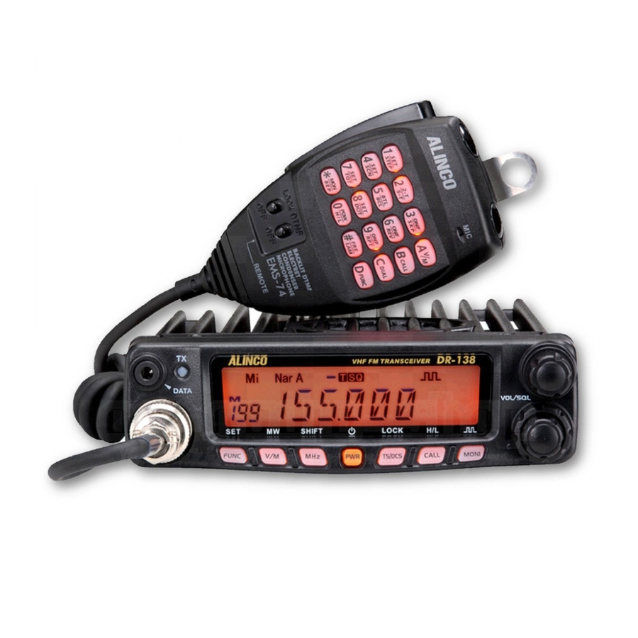
Do you have a question about the DR-138 and is the answer not in the manual?
Questions and answers
ALLAN LEWIS
March 25, 2025
If i do a restore will it restior all channels that were in the unit?
2 comments:
ALLAN LEWIS
March 25, 2025
Alinco Dr-138
Mr. Anderson
March 25, 2025
Restoring the Alinco DR-138 to its initial settings will erase temporary settings and return the unit to default values. However, the provided information does not confirm whether previously stored channels will be restored after a reset.
Page 1
Y odoyabashi Dai-bldg 13F 4-4-9 Koraibashi, Chuo-ku, Osaka 541-0043 Japan Phone: +81-6-7636-2362 Fax: +81-6-6208-3802 http://www.alinco.com E-mail:export@alinco.co.jp DR-138: VHF FM Transceiver 136.000-173.995MHz DR-438: UHF FM Transceiver 400.000-469.995MHz All EU and EFTA member states. Operator license is required. Copyright Alinco, lnc. PS0665B/FNEG-NL...
NOTE: DR-138/DR-438 may be delivered to you after dealer- programming. In such cases, please ask your dealer about the available features in your unit and how to operate this unit.
Alinco. Inc, Osaka, Japan, English Edition Printed in China.
Page 4
INFORMATION SAFETY TRAINING radio by the manufacturer or an antenna specifically authorized by the manufacturer for use with this radio. WARNING: • DO NOT transmit for more than 50% during the time of employment This radio generates RF electromagnetic energy during transmission. (50% duty cycle or less).
FCC INFORMATION Use of third party accessory may result in damage to this product. It will void our warranty for repair. FOR CLASS B UNINTENTIONAL RADIATORS: Handling this product This equipment has been tested and found to comply with the limits for a Class B digital device, pursuant to part 15 of the FCC Rules.
Alert Alert Environment and condition of use Environment and condition of use Do not use the product in proximity to a TV or a radio. It may cause It is recommended that you check local traffic regulations regarding the use of interference or receive interference.
The standard accessories may vary slightly depending on the version you have purchased. Please contact your local authorized Alinco dealer should you have any questions. Alinco and authorized dealers are not responsible for any typographical errors there may be in this manual. Standard accessories may change without notice.
Initial Installation Determine the appropriate angle of the transceiver, using the 3 screw Mobile installation hole positions on the side of the mounting bracket. The transceiver may be installed in any position in your car, where the controls and microphone are easily accessible and it does not interfere with the safe operation of the vehicle.
Initial Installation Connect the DC power cable to the transceiver's power supply DC Power Cable Connection connector. Press the connectors firmly together until the locking tab clicks. Mobile Operation The vehicle battery must have a nominal rating of 12V. Never connect the transceiver to a 24V battery.
Page 12
Initial Installation ACC terminal Connect the transceiver's DC power connector to the connector the DC power cable. Cigar-Plug connection Press the connectors firmly together until the locking tab clicks Optional EDC-43 required Before connecting the DC power to the transceiver, be sure to switch the transceiver and the DC power supply OFF.
Initial Installation Accessories Connections Power supply voltage Display After connecting the transceiver to the power supply, the supply voltage External Speaker can be displayed on LCD by pressing the key together with the If you plan to use an external speaker, choose a speaker with an key.
Page 14
Initial Installation Microphone For voice communications, connect a provided microphone into the socket on the front of the main unit. Turn the ring firmly on the plug until it locks. Attach the supplied microphone hanger in an appropriate location using the screws included in the screw set. Antenna Microphone [EMS-74] Microphone...
Getting Acquainted Front panel Microphone connection port Mic.connector Press key until icon appears then press the following key. NO. KEY FUNCTION FUNC/SET Confirms the selective functions and exit V/M/MW Stores data into channels MHz/SHIFT Sets offset direction and offset frequency TS/DCS/LOCK Sets Keypad lock function Switches between HI, MID and LOW power...
Getting Acquainted Rear panel NO. KEY Å FUNCTION (Not in use) Memory mode. Indicates the channel number in memory mode. Channel skip. Indicates the decimal point of frequency and the Decimal point scanning function. Indicates the frequency or memory name. Signal is being received or monitor.
Getting Acquainted microphone MIC Connector Diagram(in the front view of connector) NO. KEY FUNCTION Increase frequency, channel number or setting value. DOWN Decrease frequency, channel number or setting value. Push-To-Talk key to transmit. Numerical Keyd Input VFO frequencies and other various oprations DTMF ON/OFF Switches between DTMF and function operations.
(As pic 1) In addition, the programming software is made available to B. Channel + Name Tag Mode: When dealers only and Alinco releases the software only to the set display as "NM", it enters into authorized importers.
Basic Operations be masked. In this status, turn Main Dial or Microphone [ symbol stands for restricted or optional functions. Features and/ or operations may not be available to commercial-mode users unless ] key will increase or decrease frequency quickly by pre-programmed by the dealer.
Basic Operations MEMORY CHANNEL PROGRAMMING Please hold the microphone approximately 2.5-5.0cm from your lips , and then speak into the microphone in your normal speaking voice. Under frequency mode (VFO), turn Main While transmitting, LED lights RED and TX-meter shows relative power level. Dial to select the desired frequency or Release PTT to receive.
KEY OPERATIONS squelch off/squelch off momeNTARY CTCSS/DCS Encode and Decode setup Many repeaters require a CTCSS tone or Squelch Off: Press key to disable squelch, press key again a DCS code encode setting as a “key” to to resume squelch. This is set by programming software as an access the system, so-called “selective- option.
KEY OPERATIONS UP / DOWN keys) to enter the setting and return to original status. The : Transmits in middle power T/SQ/DCS icon will remain on the display to show the current selective- calling status. To exit, simply use the TS/DCS key and press it until the : Transmits in low power relative status icon T/TQ/DCS disappears.
KEY OPERATIONS means transmitting frequency higher than receiving frequency. While pressing and holding key, press key to enter the auto-dialer enquiry mode, LCD displays current default data and When LCD displays " " icon, it indicates negative offset, which current group displayed on left. If no data in current group, it shows means transmitting frequency lower than receiving frequency.
PARAMETER SETTING MODE programming software. IMPORTANT: All or a part of operation in this chapter may not be available to dealer-programmed units. Press and hold key for over 2 The default setting list is available on P29. seconds to enter into setting menu. Press and hold key for over 2 seconds to enter the parameter Press...
PARAMETER SETTING MODE Turn Main Dial to select the desired 5-TONE group, Press [ PTT] to In 5Tone signaling mode, press for 2 seconds until LCD transmit selected group. displays "AN---", turn Main Dial to select desired digit(caller ID). In this mode, press to confirm existing digit and move cursor Total:100groups, 00-99, Default:00.
PARAMETER SETTING MODE Turn Main Dial to select the desired setting. If select "SQ", it indicates you can hear the calling from caller when receive a matching carrier. HI: High TX Power (60W/45W narrow) If LCD displays "CTC",it indicates MI : Middle TX Power (25W) you can hear the calling from caller LOW: Low TX Power (10W) when receive a matching carrier and...
PARAMETER SETTING MODE Turn Main Dial to select the desired Editing Channel NAME (Available only in Memory mode) setting. In memory-mode, press and hold On:In current channel, press PTT to for over 2 seconds to enter setting menu. transmit Press key to choose No.11 menu, LCD displays cursor and flashing.
PARAMETER SETTING MODE Talk Around Scrambler setup (Encryption) By Talk Around function, you can directly communicate with other radios An analog voice inversion scrambler is available as an option. This in your group in case the repeater is not activated or when you are out of special audio process can offer a more confidential communication.
PARAMETER SETTING MODE beep sound APO (Auto power off) The beep provides confirmation of entry, error status or malfunctions of Once APO is activated, the radio will be automatically switched off when the radio. You can enable or disable beep sounds. the pre-set time is elapsed.
General Setting Display iiiumination color setting Press key to choose No.24 menu, LCD displays "LAMP--25" This is to select the display illumination color. Turn Main Dial to select the desired LCD brightness; 1 to turn off, 32 to the brightest. Press and hold key for over 2 seconds to enter setting menu.
General Setting to next edition, press to clear out all This function may not be available in dealer-programmed units. digits. After finishing edition, press to confirm PIN Setup( Useless if PIN is not assigned and enter into edition of current group's ID corresponding name. Turn selector knob to select desired letter, press to move Enable this function, you have to insert a matching PIN to enter into...
Microphone Operation In this chapter, operations shown with is available to all units, is subject flashed in LCD, Press again to enable squelch and the icon disappears. to dealer-programming or restrictions. Some of features may be functional in memory mode temporary, but the setting will return to the initial parameters Switches between VFO and channel mode after changing channel or turned off the unit.
Microphone Operation OFF: Busy channel lockout is disabled. This function can be temporarily used in channel mode. Once the Press number keys to confirm and exit. radio is turned off or switched to another channel, the temporary setting will be erased and back to initial settings. Reverse TX/RX Scan Skip TX frequency turns to RX frequency &...
Microphone Operation Press number key to confirm and exit. LCD displays icon, it indicates CTCSS encode set in current channel. HIGH/MID/LOW Power Selection LCD displays icon, it indicates CTCSS encode and decode set in current channel. In standby, press , then press , LCD displays "POW-xx".
Anti-theft Alarm By removing or cutting the cable before turning on will sound alarm. To DC power cable turn off the alarm, press PWR key to turn off the power. The alarm is canceled and turns on normally when PWR key is pressed next time. Optional alarm cable [UX1259] Steering-wheel etc.
Cable Clone This feature clones the programmed data and parameters in the master unit to slave units. Use commonly available audio-cable with 3.5mm stereo-mini plugs as shown below. Make a master unit by setting and programming it as desired. Turn off both units. Connect the cable between the DATA jacks on both units. Master unit only: press and hold key, then press key to enter into cloning mode.
Maintenance Default Setting after Resetting DR-138 Trouble Shooting Problem Possible Causes and Potential Solutions DCS encode DR-138 and decode + and - polarities of power connection (a) Power is on, nothing are reversed. Connect red lead to plus VFO frequency 155.000MHz...
Specifications DR-138 General Receiver (ETSI EN 300 086 standard testing ) Wide band Narrow band Frequency Range VHF: 136-174MHz Sensitivity ≤0.25μV ≤0.35μV (12dB Sinad) Number of Channels 200 channels Adjacent Channel ≥70dB ≥60dB Selectivity 25KHz (Wide Band) Channel Spacing 20KHz (Middle Band) Intermodulation ≥65dB...
Specifications DR-438 General Receiver (ETSI EN 300 086 standard testing ) Wide band Narrow band Frequency Range UHF: 400-470MHz Sensitivity ≤0.25μV ≤0.35μV Number of Channels 200 channels (12dB Sinad) Adjacent Channel 25KHz (Wide Band) ≥70dB ≥60dB Selectivity Channel Spacing 20KHz (Middle Band) Intermodulation ≥65dB ≥60dB...
Need help?
Do you have a question about the DR-138 and is the answer not in the manual?
Questions and answers
If i do a restore will it restior all channels that were in the unit?
Alinco Dr-138
Restoring the Alinco DR-138 to its initial settings will erase temporary settings and return the unit to default values. However, the provided information does not confirm whether previously stored channels will be restored after a reset.
This answer is automatically generated