Table of Contents
Advertisement
Advertisement
Table of Contents

Related Manuals for Alinco DR-135TMkIII


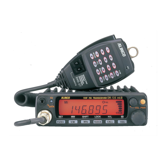
Summary of Contents for Alinco DR-135TMkIII
- Page 1 Rhein Tech Laboratories, Inc. Client: Alinco, Inc. 360 Herndon Parkway Model: DR-235TMkIII Suite 1400 Standards: FCC 15.121 Herndon, VA 20170 & IC RSS-215 http://www.rheintech.com Report: 2006179 Appendix J: Manual Please see the following pages. Page 23 of 41...
-
Page 4: Table Of Contents
Contents Warning ................3 Before operating the transceiver ........7 Introduction ................ 8 1. New and Innovative Features ........9 2. Standard Accessories ..........10 3. Initial Installation ............11 For a base station set up ..............11 For a mobile station set up ..............12 External power supply control &... - Page 5 Contents Alphanumeric Tag ................30 Dimmer ....................30 7. Advanced Operations ..........31 SCANNING FUNCTION ..............31 [VFO Scan] ................31 [Memory scan] ................ 31 • Program scan ............... 32 • Tone Scan ................32 • DCS scan ................33 KEY-LOCK FUNCTION ...............
-
Page 6: Warning
Warning To prevent any hazard during operation of Alinco's radio product, in this manual and on the product you may find symbols shown below. Please read and understand the meanings of these symbols before starting to use the product. This symbol is intended to alert the user to an immediate danger that may Danger cause loss of life and property if the user disregards the warning. - Page 7 Warning Risk of explosion if battery is replaced with an incorrect type. Dispose of, or recycle used batteries according to your local regulations. The manufacturer declines any responsibilities against loss of life and property due to a failure of this product when used with or as a part of a device made by third parties. Use of third party accessory may result in damage to this product.
- Page 8 Warning Cigar-lighter cable (for optional Igunition-key ON/OFF operation): Do not use the cable at any other than the specified ones. It may result in electric shock, fire and/or malfunction. Do not handle cigar-cable with a wet hand. It may result in electric shock. In case of emergency: In case of the following situation(s), please turn off the product, switch off the source of power, then remove or unplug the power-cord.
- Page 9 Warning About transceiver Do not connect devices other than specified ones to the jacks and ports on the product. It may result in damage to the devices. Turn off and remove the power-source (AC cable, DC cable, battery, cigar-cable, charger adapter etc) from the product when the product is not in use for extended period of time or in case of maintenance.
-
Page 10: Before Operating The Transceiver
• Turn the power off immediately if the transceiver emits smoke or strange odors. Ensure the transceiver is safe, then bring it to the nearest Alinco service center. • An operator's license is required for this device. Notice to California resident users The product that comes with this manual is free from dangerous material such as lead and cadmium as per RoHS order of EU. -
Page 11: Introduction
Introduction Thank you very much for purchasing this excellent Alinco transceiver. Our products are ranked among the finest in the world. This radio has been manufactured with state of the art technology and it has been tested carefully at our factory. It is designed to operate to your satisfaction for many years under normal use. -
Page 12: New And Innovative Features
1. New and Innovative Features Your new radio features some of the most advanced functions and reliable engineering available anywhere. The ALINCO design philosophy is focused on developing innova- tive usable features, including the following: • Three different styles of display are available on a large LCD panel including fre- quency, channel number or 7 digit alphanumeric label. -
Page 13: Standard Accessories
The standard accessories may vary slightly depending on the version you have purchased. Please contact your local authorized Alinco dealer should you have any questions. ALINCO and authorized dealers are not responsible for any typographical errors there may be in this manual. Standard accessories may change without notice. -
Page 14: Initial Installation
Use a regulated power supply capable of providing continuous current of 12A or more. Power supplies that do not meet those specifications may cause malfunction and/or damage to the radio and will void the warranty. Alinco offers excellent communication-grade power supplies as optional accessories. Please contact your local authorized Alinco dealer. -
Page 15: For A Mobile Station Set Up
3. Initial Installation For a mobile station set up Location The transceiver may be installed in any position in your car, where the controls and microphone are easily accessible and it does not interfere with the safe operation of the vehicle or the performance of the set. If your vehicle is equipped with air bags, be certain your radio will not interfere with their deployment. -
Page 16: External Power Supply Control & Power Lamp Functions
3. Initial Installation External power supply control & power lamp functions ACC terminal Cigar-Plug connection Ext. Power jack Battery DC cable Be sure the vehicle has a negative-ground, 12VDC electric system before installation. Connect the provided DC cable directly to the battery as shown below to minimize any possible ignition noise. Be sure the vehicle has a large capacity battery as the use of the transceiver may overload the electric system of the vehicle. -
Page 17: Part Names And Functions
4. Part Names and Functions Front Panel •Primary Functions No. Key Function 1 PWR Power turns ON / OFF whenever the key is pressed. 2 Volume knob Adjusts the AF audio level. 3 Dial Changes the frequency, memory channel and scan direction. 4 FUNC/SET Sets the function mode to access additional settings. -
Page 18: Rear Panel
4. Part Name of Functions • Functions that can be activated while pressing the FUNC Key No. Key Function 1 PWR Reset to factory default settings. 5 V/M/MW Erase the memory. 6 MHZ/SHIFT Switches to wide / narrow mode. 7 TSDCS/LOCK Sets the auto dialer. 8 CALL/H/L Accesses the clone function mode. -
Page 19: Display
4. Part Names and Functions Display No. Key Function 1 SQL Appears when setting the squelch level. Appears when in memory mode. Indicates the memory channel number in memory mode. 4 .Decimal point Appears when setting the theft alarm function. 5 .Decimal point Appears when setting the skip level. -
Page 20: Microphone
4. Part Name of Functions Microphone T version E version No. Key Function 1 UP Increase the frequency, memory channel number, or setting value. 2 DOWN Decrease the frequency, memory channel number, or setting value. 3 PTT Press the PTT(Push-To-Talk)key to transmit. 4 DTMF DTMF tone keys Set to DTMF when you don’t want to operate remote con-... -
Page 21: Basic Operations
5. Basic Operations Turning the unit on and off PWR key Press the power switch or turn the ignition key to ACC or ON position according to the option selected during installation. Press the power switch again or turn the ignition key to OFF position to turn off. -
Page 22: Vfo Mode
5. Basic Operation VFO mode VFO tuning is set as a default mode at the factory. VFO (vari- able frequency oscillator) allows you to change the frequency in accordance with the selected channel step as you rotate the VFO mode main dial or by using the UP/DOWN keys on the microphone. -
Page 23: Changing The Channel Step
5. Basic Operation Changing the channel step Be sure the unit is in VFO mode. Refer to P.26 to enter into the Parameter Setting(SET) mode. Select the channel step setting (P.26) using the Display for channel step tuning knob. The current channel step will be displayed as below. -
Page 24: Ctcss / Dcs Setting
5. Basic Operation NOTE: It is practical to use the memory mode to operate repeaters by programming the shift and offset settings into the memory channels (P.22). CTCSS / DCS setting Many repeaters require a CTCSS tone or a DCS code encode setting as a “key” to access the system, so-called “selective-calling”. -
Page 25: Memory Mode
5. Basic Operation NOTE: Depending on the deviation level of the incoming DCS coded-signal, your radio may not open the DCS squelch. If this occurs, return to DCS setting mode and press the CALL key. A decimal point appears on the 10 MHz order;... -
Page 26: [Programmable Data In The Memory Channel]
5. Basic Operation While F icon is on the display, press MW key. The VFO settings are copied to the memory channel and a beep will sound. The memory channel can be over-written if a previously pro- grammed channel is selected (the memory channels shown with a stable M icon). -
Page 27: Call Mode
5. Basic Operation CALL mode This is a memory mode that allows the transceiver to quickly recall the assigned memory channel by simply pressing the CALL key, regardless of the current status of the unit. Press CALL key. The C icon appears on the display and the transceiver enters the CALL mode. -
Page 28: To Transmit
5. Basic Operation To transmit Select the desired frequency. Be sure that you are authorized to operate on the selected fre- quency. Check the system and monitor the fre- quency to make sure that you are not going to disturb any ongoing communications. Select the output power. -
Page 29: Parameter Setting Mode
6. Parameter Setting Mode IMPORTANT: Please read the following pages thoroughly prior to the change of any parameters. THE PARAMETERS CANNOT BE SET WITHOUT ENTERING THE SET MODE. By entering the Parameter Setting mode, some of the radio’s operating parameters can be changed to suit your application. -
Page 30: Channel Step Setting
6. Parameters Setting Mode Channel Step setting This is to select the channel step to be used in the VFO mode. Refer to the chart below for the relation of the actual step frequency and how it is displayed. Note: Be sure to set the kHz order of the frequency at even-number such as .000, prior to change this parameter in VFO mode. -
Page 31: Time-Out-Timer
6. Parameters Setting Mode Time-Out-Timer The TOT feature is popular in repeater systems. It prohibits the users from transmitting on the repeater after a certain period of time has elapsed. By setting this function and activating it accord- ing to the repeaters’ requirement, the radio alerts the user by a beep 5 seconds prior to time-out. When the time is expired, transmitting stops and the transceiver automatically returns to receiving mode. -
Page 32: Apo-Auto Power Off
6. Parameters Setting Mode APO-Auto Power OFF This feature will automatically shut off the transceiver. It is useful for mobile operation to avoid draining the car battery. If there is no activity or use of the radio, it will turn off automatically after 30 minutes followed by a beep sound. -
Page 33: Alphanumeric Tag
6. Parameters Setting Mode Alphanumeric Tag The memory channels stored in the memory-mode can be displayed with an alphanumeric tag instead of the default frequency display. Program the memory channel first. There are 67 characters available including A-Z, 0-9. Enter the set mode while the unit is in memory mode. -
Page 34: Advanced Operations
7. Advanced Operations Your transceiver offers different features for advanced operations. SCANNING FUNCTION Use this function to automatically search for signals. 6 different scan types are available in the unit. In parameter setting mode, choose Timer mode or Busy mode to determine the desired resuming condition. -
Page 35: Program Scan
7. Advanced Operations •Program Scan This is a type of VFO scan, but by setting the frequency range The Highest band edge of the VFO into PH and PL channels, it only scans between Range (a) those frequencies. With setting the PH and PL properly, up to 3 Program scan ranges will be available. -
Page 36: Dcs Scan
7. Advanced Operations •DCS scan Same as previous, but for DCS code search. Press TS/DCS key to enter DCS setting mode. Press UP/DOWN key for more than 1 second but less than 2 seconds to start. It searches the 104 DCS codes in order. The 10 MHz order decimal point will flash. -
Page 37: Digital Voice Communication
7. Advanced Operations Digital voice communication By installing an optional digital unit EJ-47U, digital voice communication becomes possible. Install EJ-47U to the connecter CN105 of the unit. See the instruction that comes with EJ- 47U for assembling details. Press the FUNC key, and then press the SQL key while the [F] icon is displayed. -
Page 38: Auto-Dialer
7. Advanced Operations AUTO-DIALER This will automatically transmit pre-programmed DTMF tones. DTMF (Dual-Tone-Multi-Fre- quency) are the same tones used in the telephone system, and they are often used to remote control electronic devices or AUTOPATCH phone systems available on some repeaters. To program tones in the Auto-dialer memory: Press FUNC key and TS/DCS key at the same time to enter the setting mode. -
Page 39: Theft Alarm
7. Advanced Operations THEFT ALARM (Optional ADALM135 required for FXE models) This alert uses a beep sound when the unit is about to be removed in an improper manner. This function is useful when the unit is installed in a vehicle. DC power cable (ADALM135) Alarm cable A... -
Page 40: Am Mode Reception (Dr235Tmk Only)
7. Advanced Operations [Operation 2] Choose this operation when a delay period is desired. Enter the Parameter setting mode as described previously and select SCR-DLY. Follow the previous instruction to set. Turn off the unit. Display will disappear but the LCD illumination stays on. After 20 seconds TX LED lights up, illumination dims, and alarm functions. -
Page 41: Cable Clone
7. Advanced Operations CABLE CLONE This feature will copy the programmed data and parameters in the master unit to slave units. It copies the parameters and memory program settings. Connection Make a cable using 3.5 mm stereo-mini plugs as shown below. Make a master unit by setting and programming it as desired. -
Page 42: Packet Operation
8. PACKET OPERATION Packet mode is high-speed data communication using a personal computer. The use of a Digital repeater network (Digi-peaters), including satellites, offers communications with distant stations. In order to operate in the packet mode, it is essential that the station is equipped with a personal computer with appropriate packet software, 9 pin RS-232C cable, optional EJ-41U TNC unit or external TNC (terminal node controller). - Page 43 If it is replaced in wrong way, it may cause damages to the EJ- 41U and/or the radio risking even the explotion of components. A soldering iron is required for the task and if you are not confident, please consult with your local Alinco dealer for the replacement. EJ-41U (option)
-
Page 44: [To Operate Packet Using An External Tnc]
8. PACKET OPERATION [To operate packet using an external TNC] Use the DSUB-9 connector to connect the radio and the PC. The pin allocation for the DSUB-9 on the back of the unit is as follows: Transceiver 1200 bps FM Packet TNC DATA DATA Packet RX OUT... -
Page 45: [To Operate Aprs ]
8. PACKET OPERATION •1200bps Connect Pins 4, 5, 7, 9, and 1 and 8 also depending on the requirement. It enables a conventional 1200bps packet mode. •9600bps Connect Pins 2, 3, 5, 7, and 1 and 8 also depending on the requirement. Press FUNC key, while F icon is on, press SQL. -
Page 46: [Set Up]
8. PACKET OPERATION [SET UP] Please refer to the previous chapter for the set up and installation of the EJ-41U unit, TNC and PC. See below for the connection of a GPS receiver. It requires a 3.5mm stereo plug to connect to the DATA Terminal on the radio's front panel. -
Page 47: Remote Control Operation
9. Remote Control Operation With using an EMS 57 microphone (may be optioned), the transceiver can be controlled remotely by operating the DTMF keys on the microphone. Frequencies can also be entered directly from the microphone. LOCK DTMF OFF OFF Enter the remote command or the frequency. -
Page 48: [Entering A Frequency Directly]
9. Remote Control Operation [Entering a frequency directly] Frequencies can be entered directly by pressing the numerical (1~0) keys. Only valid numbers will be accepted and entered to the display. Set the microphone REMOTE / DTMF switch to the REMOTE position. DTMF keys can be used to enter ftom the 100 MHz digit. -
Page 49: Maintenance / Reference
10. Maintenance / Reference Reset Resetting the transceiver returns all programmed contents to their factory default setting. If any problems persist, resetting may overcome them and return the transceiver to normal opera- tion. Reset Procedure While holding the FUNC key down, turn the power on. All segments of the LCD will be displayed, then default set- tings are displayed. -
Page 50: Trouble Shooting
10. Maintenance / Reference Trouble Shooting Please check the list below before concluding that the transceiver is faulty. If a problem persists, reset the transceiver. This can sometimes correct erroneous operation. Problem Possible Causes and Potential Solutions (a) Power is on nothing + and - polarities of power connection are reversed. -
Page 51: Optional Accessories
• EMS-53 Microphone • EDC-36 Cigar-plug cable with filter (for Cigar-plug connection. Recommended in case other Alinco handheld transceivers may be used in the vehicle, as this cable can also power the handheld units. See its manual for compatibility) • EDC-37 DC cable... -
Page 52: Specifications
12. Specifications DR-135EMk / FXE: VHF FM MOBILE TRANSCEIVER 144.000-145.995MHz DR-435EMk / FXE: UHF FM MOBILE TRANSCEIVER 430.000-439.995MHz CE0336 This device is authorized for use in all EU and EFTA member states. An operator's license is required for this device. -
Page 53: Appendix
Appendix TNC Commands List The commands supported by the built-in TNC are list below. You must enter a space between a command name (or short-form) and a parameter, or between two parameters; ex.AU OFF. Command form Default Parameters Description Name Short AUTOLF ON/OFF... - Page 54 Appendix Command form Default Parameters Description Name Short FIRMRNR ON/OFF The other station sends a notice (packet) to you if it is not ready to receive data. When ON, receiving such a notice causes the TNC to suspend transmission until it receives a “ready”...
- Page 55 Appendix Command form Default Parameters Description Name Short RESET RESET Restores the default status for all the commands. RESPTIME Specifies the acknowledgement packet transmission delay. The unit of the parameter is 100 milliseconds. RESTART RESTART Causes the TNC function as if it is switched OFF then ON. RETRY Specifies the number of transmission retries.
Need help?
Do you have a question about the DR-135TMkIII and is the answer not in the manual?
Questions and answers