Raymarine e7 Installation Instructions Manual
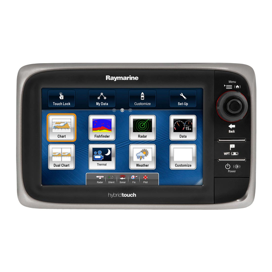
Multifunction display
Hide thumbs
Also See for e7:
- User reference (320 pages) ,
- Installation and operation handbook (135 pages) ,
- Manual (85 pages)

Related Manuals for Raymarine e7


Summary of Contents for Raymarine e7
- Page 1 e 7 / e 7 D Mu lt ifu n c t io n d is p la y Ins ta lla tion ins tructions Docume nt numbe r: 87136-2 Da te : 10-2011...
- Page 3 , SeaTalk and Sportpilot are registered trademarks of Raymarine UK Limited. RayTalk, Seahawk, Smartpilot, Pathfinder and Raymarine are registered trademarks of Raymarine Holdings Limited. FLIR is a registered trademark of FLIR Systems, Inc. and/or its subsidiaries. All other trademarks, trade names, or company names referenced herein are used for identification only and are the property of their respective owners.
-
Page 5: Table Of Contents
Contents Chapter 1 Important information....... 7 2.10 Parts supplied ............31 2.11 Tools required for installation ........32 TFT Displays ..............8 Water ingress ..............9 Chapter 3 Cables and connections......33 Disclaimers ..............9 3.1 General cabling guidance .......... 34 Chart cards and memory cards..........9 3.2 Connections overview .......... - Page 6 6.4 GPS troubleshooting ..........93 6.5 Sonar troubleshooting ..........94 6.6 Thermal camera troubleshooting ........ 96 6.7 System data troubleshooting........99 6.8 Video troubleshooting..........100 6.9 WiFi troubleshooting..........101 6.10 Bluetooth troubleshooting ........102 6.11 Touchscreen troubleshooting........103 e7 / e7D — Installation instructions...
-
Page 7: Chapter 1 Important Information
Chapter 1: Important information Warning: Switch off power supply Ensure the vessel’s power supply is switched OFF Warning: Product installation and before starting to install this product. Do NOT connect operation or disconnect equipment with the power switched on, unless instructed in this document. This product must be installed and operated in accordance with the instructions provided. -
Page 8: Tft Displays
The colors of the display may seem to vary when viewed against a colored background or in colored light. This is a perfectly normal effect that can be seen with all color Thin Film Transistor (TFT) displays. e7 / e7D — Installation instructions... -
Page 9: Water Ingress
(as applicable). When archiving data, Raymarine recommends the use of quality Raymarine does not warrant that this product is error-free or that it branded memory cards. Some brands of memory card may not is compatible with products manufactured by any person or entity work in your unit. -
Page 10: Emc Installation Guidelines
Requirement for ferrites on non-Raymarine cables – At least 1 m (3 ft) from any equipment transmitting or cables If your Raymarine equipment is to be connected to other equipment carrying radio signals e.g. VHF radios, cables and antennas. using a cable not supplied by Raymarine, a suppression ferrite In the case of SSB radios, the distance should be increased MUST always be attached to the cable near the Raymarine unit. -
Page 11: Product Disposal
Directive requires the recycling of waste electrical and electronic equipment. Whilst the WEEE Directive does not apply to some Raymarine products, we support its policy and ask you to be aware of how to dispose of this product. Warranty registration To register your Raymarine product ownership, please visit www.raymarine.com... - Page 12 / e7D — Installation instructions...
-
Page 13: Chapter 2 Planning The Installation
Chapter 2: Planning the installation Chapter contents • 2.1 Handbook information on page 14 • 2.2 Installation checklist on page 14 • 2.3 System integration on page 15 • 2.4 System Limits on page 23 • 2.5 Multiple data sources (MDS) overview on page 23 •... -
Page 14: Handbook Information
• e7D Multifunction display. Site all equipment e7 / e7D handbooks Route all cables. The following handbooks are applicable to the e7 / e7D multifunction Drill cable and mounting holes. display: Make all connections into equipment. All documents are available to download as PDFs from www.raymarine.com... -
Page 15: System Integration
2.3 System integration Your multifunction display is compatible with a wide range of marine electronics devices. SMART RAY240 D12142-1 The display uses a number of protocols to transfer data between the various devices in your system. The following table details which devices may be connected to your display, and the type of connections (in terms of protocols and physical interfaces): Planning the installation... - Page 16 Item Device Type Maximum quantity Suitable Devices Connections Remote control 1 per e7 / e7D multifunction Raymarine RCU-3 Bluetooth display. Smartphone 1 per e7 / e7D multifunction For chartplotter sync with Navionics Marine • Chartplotter sync with Navionics Marine app: display.
- Page 17 • ST70. • ST70+. • ST70+ keypads. • ST45. • i70. Instruments — third-party • Connections to e7 / e7D NMEA 0183–compatible instruments. NMEA 0183 NMEA output: 4. • Connections to e7 / e7D NMEA inputs: 2 Planning the installation...
- Page 18 Course computer — SeaTalk (via optional SeaTalk to SeaTalk SeaTalk, SeaTalk , or NMEA 0183. Raymarine converter): • ST1000. • ST2000. • S1000. • S1. • S2. • S3. SeaTalk • All SPX course computers. e7 / e7D — Installation instructions...
- Page 19 Vessel trim tabs — third-party 1 pair Third-party NMEA 2000 interfaces. NMEA 2000 (via optional DeviceNet adaptor cables). Video / camera 1 per e7 / e7D multifunction Composite PAL or NTSC video source. BNC connector. display. Lifetag (Man overboard alert) 1 basestation All Raymarine Lifetag basestations.
- Page 20 Item Device Type Maximum quantity Suitable Devices Connections Sonar transducer Direct connection to display (“D” e7 variants Raymarine transducer connection, OR Minn only): Kota transducer connection. • Raymarine P48. • Raymarine P58. ; OR: • Any 600 watt DSM-compatible transducer (via optional E66066 adaptor cable).
- Page 21 Connections Additional multifunction SeaTalk (recommended): SeaTalk display(s) — Raymarine • e7 / e7D multifunction display. • E90W, E120W, E140W multifunction display (must be running software version 2.49 or later). • G-Series (must be running software version 4.49 or later). Note: You can connect Raymarine...
- Page 22 • Navionics Silver • Navionics Gold • Navionics Gold+ • Navionics Platinum • Navionics Platinum+ • Navionics Fish’N Chip • Navionics Hotmaps Refer to the Raymarine website (www.raymarine.com) for the latest list of supported chart cards. e7 / e7D — Installation instructions...
-
Page 23: System Limits
The following limits apply to the number of system components that Installations that include multiple instances of data sources can can be connected in an e7 / e7D system. cause data conflicts. An example is an installation featuring more than one source of GPS data. -
Page 24: Networking Constraints
• Any system featuring e7 / e7D display(s) and an E90W, E120W, • e7 / e7D systems support the use of one radar scanner at a time. or E140W display connected using SeaTalk must have one of •... -
Page 25: Typical Systems
SeaT alk / RayNet SeaT alk D12143-1 1. Multifunction display. 2. Raymarine network switch. 3. Digital radome scanner. 4. SPX course computer. 5. Pilot controller. Note: A network switch is only required if more than one device is connected using SeaTalk / RayNet. - Page 26 3. Digital radome scanner. 4. SPX course computer. 5. SeaTalk pilot controller. 6. SeaTalk to SeaTalk converter. Note: A network switch is only required if more than one device is connected using SeaTalk / RayNet. e7 / e7D — Installation instructions...
- Page 27 Example: Expanded system SeaT alk DeviceNet SeaT alk / RayNet SeaT alk / RayNet SeaT alk / RayNet D12144-1 Planning the installation...
- Page 28 6. Instrument. 7. AIS receiver / transceiver. 8. Audio system. 9. Smartphone. 10. DeviceNet spur (for NMEA 2000 devices). 11. Raymarine network switch. 12. Multifunction display. 13. GPS receiver. 14. Thermal camera. 15. Wireless connection. e7 / e7D — Installation instructions...
-
Page 29: System Protocols
2.8 System protocols Seatalk SeaTalk (Next Generation) is an enhanced protocol for connection Your Multifunction Display can connect to various instruments and of compatible marine instruments and equipment. It replaces the displays to share information and so improve the functionality of older SeaTalk and SeaTalk protocols. -
Page 30: Data Master
Typical examples are: data master. • 4800 baud rate. Used for general purpose communications, including FastHeading data. • 9600 baud rate. Used for Navtex. • 38400 baud rate. Used for AIS and other high speed applications. e7 / e7D — Installation instructions... -
Page 31: Parts Supplied
2.10 Parts supplied 1. Sun cover. 2. Front bezel. 3. Multifunction display. 4. Rear bezel (required for trunnion bracket mounting). 5. Gasket (required for flush mounting). 6. Screw pack, includes: • 4 x rear bezel fixing screws. • 4 x unit mounting screws (for flush mounting). •... -
Page 32: Tools Required For Installation
8. Drill bit for flush mounting. D12171-1 1. Power drill. 2. Jigsaw. 3. Pozidrive screwdriver. 4. Adhesive tape. 5. Drill bit for trunnion bracket mounting. 6. File. 7. 25 mm hole saw for flush mounting. e7 / e7D — Installation instructions... -
Page 33: Chapter 3 Cables And Connections
Chapter 3: Cables and connections Chapter contents • 3.1 General cabling guidance on page 34 • 3.2 Connections overview on page 35 • 3.3 Power connection on page 35 • 3.4 Network connections on page 39 • 3.5 GPS connection on page 49 •... -
Page 34: General Cabling Guidance
• Unless otherwise stated use only standard cables of the correct type, supplied by Raymarine. Strain relief • Ensure that any non-Raymarine cables are of the correct quality Ensure adequate strain relief is provided. Protect connectors from and gauge. For example, longer power cable runs may require strain and ensure they will not pull out under extreme sea conditions. -
Page 35: Connections Overview
3.3 Power connection 3.2 Connections overview D12154-1 1. Sonar transducer (“D” models only). 2. SeaTalk 3. Network (for SeaTalk connections via RayNet cables). 4. Power, data, and composite video input. D12155-1 1. Multifunction display. 2. Power and data cable. 3. Connection to 12 V power supply. Cables and connections... - Page 36 9. NMEA 0183 screen (thin black wire; must be connected to ground point). Power distribution 1. Power cable to display Raymarine recommends that all power connections are made via a distribution panel. 2. Bonded common ground connection 3. Battery • All equipment must be powered from a breaker or switch, with appropriate circuit protection.
-
Page 37: Power Cable
Note: The suitable fuse rating for the thermal breaker is Cable Part number Notes dependent on the number of devices you are connecting. If in doubt consult an authorised Raymarine dealer. 1.0 m (3.3 ft) Power and R62379 Supplied with unit. data cable... - Page 38 +VE bar -VE bar Where possible, connect individual items of equipment to individual circuit breakers. Where this not possible, use individual in-line fuses to provide the necessary protection. Circuit breaker Fuse Fuse e7 / e7D — Installation instructions...
-
Page 39: Network Connections
Digital Sounder Module (DSM) or radar scanner. • Thermal camera. Note: A network containing more than a single connection requires a Raymarine network switch. This is a hub used for connecting multiple devices. Typical SeaTalk network... - Page 40 Network hardware – Additional Raymarine network switch. – PC or laptop using Voyager planning software. Item Part number Notes • Network — for connecting the following devices to a Raymarine SeaTalk network E55058 8–way hub for network network switch: switch connection of multiple –...
- Page 41 Radomes and digital Open Array radar scanners. The scanner is connected using a SeaTalk cable. The digital radar is usually connected via a Raymarine network switch. On smaller systems (with only one display and no other digital devices) the radar may be connected directly using a SeaTalk crossover coupler.
- Page 42 4. RayNet cable. 5. Connection to power supply — Open Array scanners require a VCM (Voltage Converter Module). Note: The connector on the free end of the radar cable does NOT have a locking mechanism. D12150-1 e7 / e7D — Installation instructions...
- Page 43 D12152-1 1. Radar extension cable. 2. Radar power and data digital cable. 3. Raymarine network switch (or crossover coupler if connecting radar directly to display). 4. RayNet cable. Note: The extension cable connects to the radar scanner. Note: The power connection is NOT shown in the diagram. If using an Open Array scanner a VCM (Voltage Converter Module) must be connected between the scanner and the power supply.
- Page 44 Non-”D” variant models require a connection to an external Raymarine DSM unit. Internal and external DSM units Note: The maximum length for the radar power and data digital require a connection to a compatible sonar transducer.
- Page 45 SeaT alk / RayNet • Raymarine P48. • Raymarine P58. • Minn Kota transducers (“D” variant Raymarine displays only), via optional A62363 adaptor cable. • Any 600 watt DSM-compatible transducer, via optional E66066 adaptor cable. SeaT alk / RayNet Sonar transducer connection —...
- Page 46 1. Multifunction display (“D” variant). 2. E66066 adaptor cable. 3. Sonar transducer. D12160-1 1. Multifunction display. Transducer adaptor cable 2. Raymarine network switch (only required if connecting more Cable Part number than one device using SeaTalk / RayNet). 0.5 m (1.64 ft) transducer adaptor E66066 3.
- Page 47 (“D” variant models only) You can connect a thermal camera to your multifunction display. The camera is connected via a Raymarine network switch. If you want to use the optional Joystick Control Unit (JCU) with the camera this must also be connected to the network switch. A composite video connection is required between the camera and the multifunction display.
- Page 48 An Ethernet (with power) cable is used to connect the JCU. The JCU is supplied with a 7.62 m (25 ft) Ethernet cable for this connection. If you require a different length contact your dealer for suitable cables. e7 / e7D — Installation instructions...
-
Page 49: Gps Connection
3.5 GPS connection GPS connection — NMEA 0183 The multifunction display includes an internal GPS receiver. It can also be connected to an external GPS receiver, using SeaTalk or NMEA 0183. GPS connection — SeaTalk NM EA 0183 D12177-1 1. Multifunction display. 2. -
Page 50: Ais Connection
NMEA 0183. Connection using SeaTalk NM EA 0183 (4800) SeaTalk D12149-1 1. Multifunction display. 2. SeaTalk AIS receiver / transceiver. NM EA0183 (38400) D11221-3 1. VHF radio. 2. AIS unit. 3. Multifunction display. e7 / e7D — Installation instructions... -
Page 51: Fastheading Connection
• SeaTalk autopilots (for example, p70 with SmartPilot SPX course computer). • A Raymarine or third-party fastheading sensor connected to the • SeaTalk equipment via the optional SeaTalk to SeaTalk multifunction display via NMEA 0183. converter. - Page 52 12 V power supply. Power may be provided from: SMART • Raymarine equipment with a regulated 12 V power supply (for example, a SmartPilot SPX course computer); or: • Other suitable 12 V power supply. Note: SeaTalk...
- Page 53 SeaTalk cables and accessories Connection / Cable Notes SeaTalk cables and accessories for use with compatible products. Backbone cable (various lengths) The main cable carrying data. Spurs from the backbone are used to Description Part No Notes connect SeaTalk devices. Backbone Kit A25062 Includes:...
- Page 54 Allows the connection converter of SeaTalk devices to a SeaTalk system. SeaTalk Inline A80001 Provides direct terminator connection of a spur cable to the end of a backbone cable. No T-piece required. SeaTalk Blanking plug A06032 e7 / e7D — Installation instructions...
-
Page 55: Seatalk Connection
3.9 SeaTalk connection SeaTalk accessories SeaTalk cables and accessories for use with compatible products. You can connect SeaTalk devices to your multifunction display using the optional SeaTalk to SeaTalk converter. Description Part No Notes NMEA / SeaTalk E85001 converter 3 m (9.8 ft) SeaTalk D285 extension cable 5 m (16.4 ft) SeaTalk... -
Page 56: Nmea 0183 Connection
0183 OUTPUT (Port 1). You can connect a total of 2 NMEA 0183 devices to the display’s NMEA 0183 INPUT (Port 2). NM EA DEVICE NM EA DEVICE 4800 / 9600 / 38400 baud 4800 / 9600 / 38400 baud D12169-1 e7 / e7D — Installation instructions... - Page 57 Item Device Cable color Port Input / output Positive (+) / negative (-) Multifunction display White Input Positive Green Input Negative Yellow Output Positive Brown Negative Output Orange / white Input Positive Orange / green Input Negative NMEA device Refer to instructions Refer to instructions Output Positive...
-
Page 58: Nmea 0183 Cable
The following restrictions apply to any extension to the NMEA 0183 data wires. Total length (max) Cable Up to 5 m High quality data cable: • 2 x twisted pair with overall shield. • 50 to 75 pF/m capacitance core to core. e7 / e7D — Installation instructions... -
Page 59: Nmea 2000 Connection
3.11 NMEA 2000 connection Connecting the display to an existing NMEA 2000 (DeviceNet) backbone The display can receive data from NMEA 2000 devices (e.g. data from compatible engines). The NMEA 2000 connection is made using SeaTalk and appropriate adaptor cables. You can EITHER: •... -
Page 60: Video Connection
• Portable digital video player. D12178-1 1. Multifunction display. 2. Power and data cable. 3. Video connector. 4. Video source — for example, video camera. Video specification Signal type Composite Format PAL or NTSC Connector type BNC (female) e7 / e7D — Installation instructions... -
Page 61: Bluetooth Connections
The media player must be compatible with the Bluetooth AVRCP protocol (version 2.1 or higher). 2. Bluetooth connection. 3. Raymarine Bluetooth remote control (for example, RCU-3). To use the remote control you must first: • Enable Bluetooth in the System Settings on the multifunction display. -
Page 62: Wifi Connections
• Enable WiFi in the System Settings on the multifunction display. • Enable WiFi on your iPhone or iPad. • Select the Raymarine WiFi connection from the list of available WiFi networks on your iPhone or iPad. e7 / e7D — Installation instructions... - Page 63 • Enable WiFi in the System Settings on the multifunction display. • Enable WiFi on your iPhone or iPad. • Select the Raymarine WiFi connection from the list of available WiFi networks on your iPhone or iPad. Cables and connections...
- Page 64 / e7D — Installation instructions...
-
Page 65: Chapter 4 Location And Mounting
Chapter 4: Location and mounting Chapter contents • 4.1 Selecting a location on page 66 • 4.2 Removing the rear bezel on page 68 • 4.3 Flush mounting on page 69 • 4.4 Attaching the rear bezel on page 70 •... -
Page 66: Selecting A Location
Ensure the unit is mounted in a location which allows proper routing and connection of cables: – Minimum bend radius of 100 mm (3.94 in) unless otherwise stated. – Use cable supports to prevent stress on connectors. • Water ingress e7 / e7D — Installation instructions... - Page 67 Viewing angle considerations As display contrast, color and night mode performance are all affected by the viewing angle, Raymarine recommends you temporarily power up the display when planning the installation, to enable you to best judge which location gives the optimum viewing ( 7 .
-
Page 68: Removing The Rear Bezel
Outer edges - work from the sides upwards and then along the top edge, ensuring that the clips are fully released from the display. ii. Inner edges - ensure that the bezel is completely removed from the display. e7 / e7D — Installation instructions... -
Page 69: Flush Mounting
4.3 Flush mounting 2. Fix the appropriate cutting template supplied with the product, to the selected location, using masking or self-adhesive tape. You can mount the display in a flush or panel mounting arrangement. 3. Using a suitable hole saw (the size is indicated on the template), make a hole in each corner of the cut-out area. -
Page 70: Attaching The Rear Bezel
Inner edges - ensure that the bezel sits flat against the unit. D12183-1 3. Use the supplied screws to secure the bezel to the display. e7 / e7D — Installation instructions... - Page 71 Note: The appropriate torque to use when drilling depends on the thickness of the mounting surface and the type of material. D12172-1 1. Mark the location of the mounting bracket screw holes on the chosen mounting surface. 2. Drill holes for the screws using a suitable drill, ensuring there is nothing behind the surface that may be damaged.
-
Page 72: Front Bezel
Inner edges - particularly along the chart card door edge, to ensure that the bezel sits flat. 6. Check that all control buttons are free to operate. e7 / e7D — Installation instructions... -
Page 73: Removing The Front Bezel
Removing the front bezel Important: Use care when removing the bezel. Do not use any tools to lever the bezel; doing so may cause damage. Before proceeding ensure the memory card slot door is open. 1. Place both your thumbs on the upper left edge of the display, at the positions indicated in the diagram above. - Page 74 / e7D — Installation instructions...
-
Page 75: Chapter 5 System Checks
Chapter 5: System checks Chapter contents • 5.1 Initial power on test on page 76 • 5.2 Designating the data master on page 78 • 5.3 GPS check on page 78 • 5.4 Radar check on page 81 • 5.5 Sonar check on page 83 •... -
Page 76: Initial Power On Test
D12179-1 • Placing and moving the cursor. 1. Touchscreen — you can touch the screen to operate many Note: Raymarine strongly recommends that you familiarize common functions, including all menu operations. yourself with touch operations while your vessel is anchored 2. - Page 77 3. OK button — push the end of the joystick to confirm a selection or entry. Powering the display on 1. Press and hold the POWER button until the Raymarine logo appears. 2. Press OK to acknowledge the disclaimer message.
-
Page 78: Designating The Data Master
3. Select Internal GPS. 4. Select the On or Off option as appropriate. Checking GPS operation You can check that the GPS is functioning correctly using the chart application. 1. Select the Chart page. e7 / e7D — Installation instructions... -
Page 79: Gps Setup
A solid circle on the chart indicates that neither heading nor Course Over Ground (COG) data is available. Note: Raymarine recommends that you check the displayed vessel position in the chart application against your actual proximity to a known charted object. GPS receivers typically have an accuracy of between 5 and 15 m. - Page 80 In order for your GPS receiver and multifunction display to correlate accurately with your paper charts, they must be using the same datum. e7 / e7D — Installation instructions...
-
Page 81: Radar Check
5.4 Radar check Typical HD digital radar screen Warning: Radar scanner safety Before rotating the radar scanner, ensure all personnel are clear. Warning: Radar transmission safety The radar scanner transmits electromagnetic energy. Ensure all personnel are clear of the scanner when the radar is transmitting. - Page 82 6. Press OK when complete. D11590-2 Item Description Target object (such as a buoy) dead ahead. Target displayed on the radar display is not aligned with the Ship’s Heading Marker (SHM). Bearing alignment is required. e7 / e7D — Installation instructions...
-
Page 83: Sonar Check
• “D” variant models allow the direct connection of EITHER a Raymarine OR a Minn Kota sonar transducer. • All models allow the connection of a Raymarine sonar transducer via a compatible external DSM unit. • For all models use the Transducer Set-Up menu in the fishfinder application to specify the sonar transducer you want to use. -
Page 84: Thermal Camera Setup And Checks
There are 2 ways of controlling the thermal camera using the thermal camera application: • Using the touchscreen and the UniControl’s rotary control. • Using the UniControl’s joystick and rotary controls. To pan and tilt the thermal camera using touch actions: e7 / e7D — Installation instructions... - Page 85 Move your finger up and down the screen to tilt the camera UniControl joystick — is used for rotating the camera left or up or down. right (panning), or tilting the camera up or down. UniControl rotary — is used to zoom in and out. Move your finger left and right on the screen to rotate the camera left or right (panning).
-
Page 86: Enabling Autopilot Functions
7. The Pilot Control dialog is displayed, indicating that pilot control 8. Select the AIS unit. is enabled and an autopilot is detected. The Track Targets menu is displayed. 9. Adjust the AIS options as appropriate. e7 / e7D — Installation instructions... -
Page 87: Language Selection
5.9 Language selection The system can operate in the following languages: English (US) English (UK) Chinese Danish Dutch Finnish French German Greek Italian Japanese Korean Norwegian Portuguese (Brazilian) Russian Spanish Swedish Turkish Polish Croatian With the homescreen displayed: 1. Select Customize. 2. - Page 88 / e7D — Installation instructions...
-
Page 89: Chapter 6 Troubleshooting
Chapter 6: Troubleshooting Chapter contents • 6.1 Troubleshooting on page 90 • 6.2 Power up troubleshooting on page 91 • 6.3 Radar troubleshooting on page 92 • 6.4 GPS troubleshooting on page 93 • 6.5 Sonar troubleshooting on page 94 •... -
Page 90: Troubleshooting
All Raymarine products are, prior to packing and shipping, subjected to comprehensive test and quality assurance programs. However, if you experience problems with the operation of your product this section will help you to diagnose and correct problems in order to restore normal operation. -
Page 91: Power Up Troubleshooting
6.2 Power up troubleshooting Problems at power up and their possible causes and solutions are described here. Problem Possible causes Possible solutions Power supply problem. The system (or part of it) does not start up. Check relevant fuses and breakers. Check that the power supply cable is sound and that all connections are tight and free from corrosion. -
Page 92: Radar Troubleshooting
(VCM) stuck in “sleep mode” at output = 40 V) The bearing of a target on the radar The radar bearing alignment requires Check and adjust radar bearing alignment. screen is incorrect. correcting. e7 / e7D — Installation instructions... -
Page 93: Gps Troubleshooting
• Close proximity to transmitting equipment such as VHF radio. GPS installation problem. Refer to the installation instructions. Note: A GPS Status screen is available within the Setup menu of Raymarine multifunction displays. This provides satellite signal strength and other relevant information. Troubleshooting... -
Page 94: Sonar Troubleshooting
Refer to the instructions supplied with the unit. SeaTalk / RayNet network problem. Check that the unit is correctly connected to a Raymarine network switch or crossover coupler (as applicable). Check the status of the Raymarine network switch (if applicable). - Page 95 Problem Possible causes Possible solutions Scroll speed set to zero Adjust scroll speed Incorrect speed reading Paddle wheel fault Check that the paddle wheel is clean. No speed offset set Add speed offset. Incorrect calibration Re-calibrate equipment Troubleshooting...
-
Page 96: Thermal Camera Troubleshooting
Cannot control thermal camera from Thermal camera application is not running. Ensure the thermal camera application is running on the multifunction Raymarine display or keyboard. display (as oppose to the video application which does not have camera controls). e7 / e7D — Installation instructions... - Page 97 (VIS / IR) video image . VIS / IR cable not connected. Ensure that the VIS / IR cable is connected from the camera to the Raymarine system. (The IR-only cable does not support switching). Noisy image. Poor quality or faulty video cable.
- Page 98 Image is inverted (upside down). Camera “Ball down” setting is incorrect. Ensure that the Ball down setting within the thermal camera system setup menu is set correctly. e7 / e7D — Installation instructions...
-
Page 99: System Data Troubleshooting
Check the power to the SeaTalk bus. Refer to the manufacturer’s handbook for the equipment in question. Software mismatch between equipment Contact Raymarine technical support. may prevent communication. Instrument or other system data is missing SeaTalk network problem Check that all required equipment is connected to the SeaTalk switch. -
Page 100: Video Troubleshooting
Problems with the video inputs and their possible causes and solutions are described here. Problem Possible causes Possible solutions No signal message on screen (video Cable or connection fault Check that the connections are sound and free from corrosion. image not displayed) e7 / e7D — Installation instructions... -
Page 101: Wifi Troubleshooting
Ensure that the “WiFi” option is enabled on the iPhone (available from the phone’s Settings menu). Ensure that the Raymarine connection is selected as the WiFi network. If a passcode has been specified for the multifunction display’s WiFi connection ensure that the same passcode is entered into the iPhone when prompted. -
Page 102: Bluetooth Troubleshooting
Multiple wireless devices running simultaneously (such as laptops, phones, in the vicinity. and other wireless devices) can sometimes cause wireless signal conflicts. Temporarily disable each wireless device in turn until you have identified the device causing the interference. e7 / e7D — Installation instructions... -
Page 103: Touchscreen Troubleshooting
6.11 Touchscreen troubleshooting Problems with the touchscreen and their possible causes and solutions are described here. Problem Possible causes Possible solutions Touchscreen does not operate as Touch lock is enabled Use the Trackpad to turn off the touch lock on the home screen. expected Screen is not being operated with bare Bare fingers must make contact with the screen for correct operation. -
Page 104: Miscellaneous Troubleshooting
Corrupt data / other unknown issue. Perform a factory reset. Important: This will result in the loss of any settings and data (such as waypoints) stored on the product. Save any important data to a memory card before resetting. e7 / e7D — Installation instructions... -
Page 105: Chapter 7 Technical Support
Chapter 7: Technical support Chapter contents • 7.1 Raymarine customer support on page 106 • 7.2 Third-party support on page 107 Technical support... -
Page 106: Raymarine Customer Support
Viewing product information With the homescreen displayed: Raymarine provides a comprehensive customer support service. You can contact customer support through the Raymarine website, 1. Select Set-up. telephone and email. If you are unable to resolve a problem, please 2. Select Maintenance. -
Page 107: Third-Party Support
7.2 Third-party support Contact and support details for third-party suppliers can be found on the appropriate websites. Navionics www.navionics.com Sirius www.sirius.com Technical support... - Page 108 / e7D — Installation instructions...
-
Page 109: Chapter 8 Technical Specification
Chapter 8: Technical specification Chapter contents • 8.1 Technical specification on page 110 Technical specification... -
Page 110: Technical Specification
• 2.423 kg (5.34 lb.) Viewing angle • Left / Right: 70 degrees • Top / Bottom: 70 / 50 degrees Power specification Nominal supply voltage 13.8 V dc Operating voltage range 10.2 to 15.6 V dc e7 / e7D — Installation instructions... - Page 111 Data connections Almanac Update Automatic Geodetic Datum WGS-84, alternatives available Wired connections through Raymarine displays. NMEA 0183 2x NMEA 0183 ports: Update Rate 1 second • NMEA port 1: Input and output, 4800 / 9600 / 38400 baud Antenna Patch •...
- Page 112 (www.raymarine.com) for the latest list of supported chart cards. Conformance specification Conformance • NMEA 2000 certification • WiFi Alliance certification • Bluetooth certification • Europe: 1995/5/EC • Australia and New Zealand: C-Tick, Compliance Level 2 e7 / e7D — Installation instructions...
-
Page 113: Chapter 9 Options And Accessories
Chapter 9: Options and accessories Chapter contents • 9.1 Spares and accessories on page 114 Options and accessories... -
Page 114: Spares And Accessories
Seal pack assembly R62375 (Internal) Spare parts R62374 WiFi PCB assembly Item Part number Notes MicroSD card reader R62364 Trunnion (bracket) A62358 assembly mount kit Documentation pack R62378 Flush mount panel set R62376 Front bezel R62377 e7 / e7D — Installation instructions... -
Page 115: Appendix A Nmea 0183 Sentences
Appendix A NMEA 0183 sentences Recommended minimum specific GPS transit data The display supports the following NMEA 0183 sentences. These Course over ground and ground speed are applicable to NMEA 0183 and SeaTalk protocols. Time and date Transmit Wind speed and angle Autopilot b Routes sentence Bearing and distance to waypoint... - Page 116 Recommended minimum navigation information sentence Recommended minimum specific GPS transit data sentence Water speed and heading sentence Distance travelled through the water sentence Course over ground and ground speed sentence Cross track error measured sentence e7 / e7D — Installation instructions...
-
Page 117: Appendix B Nmea 2000 Sentences
Appendix B NMEA 2000 sentences The display supports the following NMEA 2000 sentences. These are applicable to NMEA 2000, SeaTalk and SeaTalk 2 protocols. Message number Message description Transmit Receive Bridge ● ● ● 59392 ISO Acknowledgment ● 59904 ISO Request ●... - Page 118 AIS UTC and Date Report ● 129794 AIS Class A Static and Voyage Related Data ● 129801 AIS Addressed Safety Related Message ● 129802 AIS Safety Related Broadcast Message ● ● ● 130306 Wind data e7 / e7D — Installation instructions...
- Page 119 Message number Message description Transmit Receive Bridge ● ● ● 130310 Environmental parameters ● 130311 Environmental parameters message ● 130576 Small craft status ● ● ● 130577 Direction data ● 130578 Vessel speed components NMEA 2000 sentences...
-
Page 120: Appendix C Connectors And Pinouts
Current source to network No current sourced for external devices Signal Color Current sink from network No power required for interface BATT+ BATT- Black Signal SCREEN Black NMEA1 TX+ Yellow NMEA1 TX- Brown Not connected e7 / e7D — Installation instructions... - Page 121 Not connected +12V Screen Not connected CanH Not connected CanL Screen SeaTalk (not connected) Not connected Note: Use only Raymarine cables when connecting to SeaTalk Note: Use only Raymarine RayNet cables when connecting SeaTalk devices. SeaTalk connector Item Remarks Identification ST2/NMEA2000...
- Page 122 / e7D — Installation instructions...
- Page 124 www.ra ym a rin e .c o m...
Need help?
Do you have a question about the e7 and is the answer not in the manual?
Questions and answers