Raymarine e7 User Reference
Multifunctional display
Hide thumbs
Also See for e7:
- Installation and operation handbook (135 pages) ,
- Installation instructions manual (124 pages) ,
- Manual (85 pages)

Related Manuals for Raymarine e7


Summary of Contents for Raymarine e7
- Page 1 e 7 / e 7 D Mu lt ifu n c t io n d is p la y Us e r re fe re nce Docume nt numbe r: 81332-1 Da te : 08-2011...
- Page 3 , SeaTalk and Sportpilot are registered trademarks of Raymarine UK Limited. RayTalk, Seahawk, Smartpilot, Pathfinder and Raymarine are registered trademarks of Raymarine Holdings Limited. FLIR is a registered trademark of FLIR Systems, Inc. and/or its subsidiaries. All other trademarks, trade names, or company names referenced herein are used for identification only and are the property of their respective owners.
-
Page 5: Table Of Contents
Contents Chapter 1 Important information....... 9 3.4 Controls..............29 3.5 Hybridtouch overview ..........32 Safety notices..............9 3.6 Touchscreen overview ..........32 TFT Displays ..............10 3.7 Homescreen overview ..........33 Water ingress ..............11 3.8 Pages ..............34 Disclaimers ..............11 3.9 Applications .............. - Page 6 Chapter 8 Using alarms and MOB 10.3 AIS context menu..........178 functions ..............125 10.4 Enabling AIS............179 8.1 Using Man Overboard (MOB) functions ....126 10.5 Displaying AIS vectors........... 179 8.2 Alarms..............127 10.6 AIS status symbols..........180 e7 / e7D — User reference...
- Page 7 Chapter 12 Using the data application ....217 10.7 AIS silent mode............. 180 10.8 AIS target symbols ..........181 12.1 Data application overview ........218 10.9 Displaying detailed AIS target information ....182 12.2 Pre-configured datapages........219 10.10 Viewing all AIS targets ......... 183 12.3 Customizing the data application ......
- Page 8 19.1 Remote control connection ........274 19.2 Pairing the remote and configuring the UP and DOWN buttons ............. 274 19.3 Operating principles ..........275 19.4 Customizing the SHORTCUT button....... 275 19.5 Remote control functions ........276 e7 / e7D — User reference...
-
Page 9: Chapter 1 Important Information
It is the user’s responsibility to use official government charts, notices to mariners, caution and proper navigational Warning: Sonar operation skill when operating this or any other Raymarine product. • NEVER operate the sounder with the boat out of the water. -
Page 10: Tft Displays
7) wrongly illuminated pixels. These may appear as black closed. This can be confirmed by an audible click. pixels in a light area of the screen or as colored pixels in black areas. e7 / e7D — User reference... -
Page 11: Water Ingress
(as applicable). When archiving data, Raymarine recommends the use of quality Raymarine does not warrant that this product is error-free or that it branded memory cards. Some brands of memory card may not is compatible with products manufactured by any person or entity work in your unit. -
Page 12: Third Party Software License Agreements
Whilst the WEEE Directive does not apply to some Suppression ferrites Raymarine products, we support its policy and ask you to be aware of how to dispose of this product. Raymarine cables may be fitted with suppression ferrites. These are important for correct EMC performance. -
Page 13: Imo And Solas
Technical accuracy To the best of our knowledge, the information in this document was correct at the time it was produced. However, Raymarine cannot accept liability for any inaccuracies or omissions it may contain. In addition, our policy of continuous product improvement may change specifications without notice. - Page 14 / e7D — User reference...
-
Page 15: Chapter 2 Handbook Information
Chapter 2: Handbook information Chapter contents • 2.1 Handbook information on page 16 • 2.2 Handbook conventions on page 17 Handbook information... -
Page 16: Handbook Information
/ e7D handbooks The following handbooks are applicable to the e7 / e7D multifunction display: All documents are available to download as PDFs from www.raymarine.com... -
Page 17: Handbook Conventions
2.2 Handbook conventions Conventions used in this handbook. The following conventions are used throughout this handbook when referring to: Type Example Convention Icons The term "select" is used in procedures involving icons to refer to the action of selecting an on-screen icon, either using touch or by using the UniControl. - Page 18 / e7D — User reference...
-
Page 19: Chapter 3 Getting Started
Chapter 3: Getting started Chapter contents • 3.1 System integration on page 20 • 3.2 Networking constraints on page 28 • 3.3 Display power on page 29 • 3.4 Controls on page 29 • 3.5 Hybridtouch overview on page 32 •... -
Page 20: System Integration
The display uses a number of protocols to transfer data between the various devices in your system. The following table details which devices may be connected to your display, and the type of connections (in terms of protocols and physical interfaces): e7 / e7D — User reference... - Page 21 Item Device Type Maximum quantity Suitable Devices Connections Remote control 1 per e7 / e7D multifunction Raymarine RCU-3 Bluetooth display. Smartphone 1 per e7 / e7D multifunction For chartplotter sync with Navionics Marine • Chartplotter sync with Navionics Marine display.
- Page 22 • ST70. • ST70+. • ST70+ keypads. • ST45. • i70. Instruments — third-party • Connections to e7 / e7D NMEA 0183–compatible instruments. NMEA 0183 NMEA output: 4. • Connections to e7 / e7D NMEA inputs: 2 e7 / e7D — User reference...
- Page 23 Device Type Maximum quantity Suitable Devices Connections Pilot control heads — As determined by SeaTalk SeaTalk (via optional SeaTalk to SeaTalk SeaTalk, SeaTalk Raymarine or SeaTalk bus bandwidth converter):: and power loading, as • ST6002. appropriate. • ST7002. • ST8002.
- Page 24 Vessel trim tabs — third-party 1 pair Third-party NMEA 2000 interfaces. NMEA 2000 (via optional DeviceNet adaptor cables). Video / camera 1 per e7 / e7D multifunction Composite PAL or NTSC video source. BNC connector. display. Lifetag (Man overboard alert) 1 basestation All Raymarine Lifetag basestations.
- Page 25 Item Device Type Maximum quantity Suitable Devices Connections Sonar transducer Direct connection to display (“D” e7 variants Raymarine transducer connection, OR Minn only): Kota transducer connection. • Raymarine P48. • Raymarine P58. ; OR: • Any 600 watt DSM-compatible transducer (via optional E66066 adaptor cable).
- Page 26 Connections Additional multifunction SeaTalk (recommended): SeaTalk display(s) — Raymarine • e7 / e7D multifunction display. • E90W, E120W, E140W multifunction display (must be running software version 2.49 or later). • G-Series (must be running software version 4.49 or later). Note: You can connect Raymarine...
- Page 27 • Navionics Ready to Navigate. • Navionics Silver • Navionics Gold • Navionics Gold+ • Navionics Platinum • Navionics Platinum+ • Navionics Fish’N Chip • Navionics Hotmaps Refer to the Raymarine website (www.raymarine.com) for the latest list of supported chart cards. Getting started...
-
Page 28: Networking Constraints
• Any system featuring e7 / e7D display(s) and an E90W, E120W, • e7 / e7D systems support the use of one radar scanner at a time. or E140W display connected using SeaTalk must have one of •... -
Page 29: Display Power
3.3 Display power 3.4 Controls Powering the display on 1. Press and hold the POWER button until the Raymarine logo appears. 2. Press OK to acknowledge the disclaimer message. Powering the display off 1. Press and hold the POWER button until the countdown reaches zero. - Page 30 Back — go back one level (same effect as BACK button). Close — close all open menus (same effect as holding the MENU button for 3 seconds). D12180-1 e7 / e7D — User reference...
- Page 31 Using the cursor Label Feature Application The cursor is used to move around the screen. Heading vector Chart The cursor appears on the screen as a white cross. MARPA MARPA target Radar Man Over Board marker Chart, Radar Vessel’s position Chart Route leg Chart...
-
Page 32: Hybridtouch Overview
• Accessing applications. when it is not appropriate to use the touchscreen. In these situations, Raymarine strongly recommends that you activate the touch lock • Adding and editing applications pages. and use the physical keys to operate your multifunction display. -
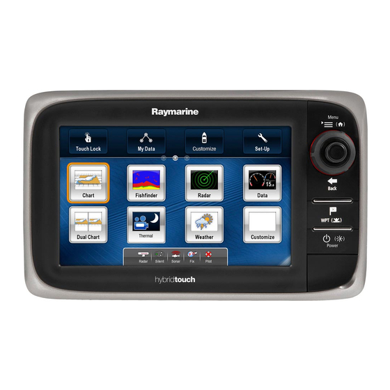
Page 33: Homescreen Overview
3.7 Homescreen overview Screen item Description Touch Lock — select this icon to lock the touchscreen, The homescreen provides a central point of access to your display’s preventing accidental use. To unlock, use the UniControl range of applications. to deselect the Touch Lock icon. •... -
Page 34: Pages
Page featuring a single application. Page featuring multiple applications. e7 / e7D — User reference... - Page 35 You can also define a "layout" for each page, which determines how 8. Use the on-screen keyboard to name the page, then select Save. the applications are arranged on the screen. Moving a page on the homescreen Changing an existing page on the homescreen With the homescreen displayed: With the homescreen displayed: 1.
-
Page 36: Applications
Weather application — (North America only). With a suitable weather receiver connected to your system, the weather application overlays historical, live, and forecasted weather graphics on a world map. e7 / e7D — User reference... -
Page 37: Screen Overview
3.10 Screen overview Thermal camera application — view and control a compatible thermal camera using your multifunction display. Video application — view a video or camera source on your multifunction display. D12196-1 Screen item Description Home — select this icon to access the homescreen. Databar —... - Page 38 The following diagram shows the main features of a pop-up menu: Using menu dialogs Menu dialogs are full-screen menus that enable you to manage data items such as waypoints and routes. The following diagram shows the main features of a standard menu: e7 / e7D — User reference...
- Page 39 Screen item Description Scroll bar — indicates your position in the list. You can also touch and drag the scroll bar to scroll the list. Options — Highlight a menu item and then click OK to access more options for that item. For example, in the Waypoint Group list you can click OK on a highlighted menu item to view the waypoints in the group, edit the group name, or erase the group.
- Page 40 Close — select this icon to close the dialog(s). Using control dialogs Control dialogs enable you to control externally connected equipment, such as an autopilot unit. The following diagram shows the main features of a typical control dialog: e7 / e7D — User reference...
-
Page 41: Editing Information In Dialogs
3.11 Editing information in dialogs With the dialog displayed: 1. Select the field you want to edit. The on-screen keyboard is displayed: D12279-1 Screen item Description Status — provides status information for the connected equipment. For example, the Pilot Control dialog displays the locked heading and current navigation mode for a connected autopilot unit. -
Page 42: Editing Numerical Values In Dialogs
You must use the UniControl to unlock the touchscreen. 3. Enter the new value using the numeric keypad. Locking the touchscreen 4. Select SAVE to save the new value. With the homescreen displayed: e7 / e7D — User reference... -
Page 43: Databar Status Symbols
3.14 Databar status symbols 1. Select the Touch Lock icon. It changes color to indicate that the touchscreen is disabled. All The status symbols on the databar confirm whether the appropriate functions are still available using the buttons and UniControl. connections to your system have been made. -
Page 44: Ais Status Symbols
Symbol static: the DSM is connected AIS currently unavailable. but not transmitting. Symbol greyed-out: the DSM is not AIS unit is switched off, or not connected. connected, or is not detected. e7 / e7D — User reference... - Page 45 GPS status symbols Symbol Description The GPS receiver status is indicated in the databar. Autopilot alarm active. Symbol Description A GPS receiver is connected and has obtained a fix. Dodge mode is active. A GPS receiver is not connected, or cannot obtain a fix.
-
Page 46: Initial Set Up Procedures
In addition to the settings covered by the Wizard, it is also Once your display has been installed and commissioned (see recommended that the following initial set up tasks are completed: Installation instructions), Raymarine recommends that you perform • Set minimum safe depth. an initial set up procedure. -
Page 47: Data Master
Data master 3. Use the Date Format, Time Format, and Local Time: UTC menu items to set your time and date preferences. Any system containing more than one networked multifunction display must have a designated data master. Adjusting the display brightness The data master is the display which serves as a primary source of data for all displays, it also handles all external sources of 1. -
Page 48: Simulator Mode
GPS antenna, radar scanner, AIS unit, or fishfinder. The simulator mode is switched on / off in the System Setup Menu. Note: Raymarine recommends that you do NOT use the simulator mode whilst navigating. Note: The simulator will NOT display any real data, including any safety messages (such as those received from AIS units). -
Page 49: Chapter 4 Managing Display Data
Chapter 4: Managing display data Chapter contents • 4.1 Memory cards overview on page 50 • 4.2 Inserting a memory card or chart card on page 50 • 4.3 Removing a memory card or chart card on page 51 • 4.4 Saving user data and user settings on page 53 •... -
Page 50: Memory Cards Overview
You can also use memory cards to backup your data. does not fit easily into the slot, check the orientation. Note: Raymarine recommends that you backup your data to a memory card on a regular basis. D12290-1... -
Page 51: Removing A Memory Card Or Chart Card
4.3 Removing a memory card or chart 3. Gently press the card all the way in to the card slot, as shown in the diagram below. The card is secure when an audible click is card heard. From the homescreen: 1. - Page 52 Note: You can also power off the multifunction display and follow steps 4 to 7 above. D12291-1 6. Use your fingers to pull the card clear of the card slot, using the edge of the card. e7 / e7D — User reference...
-
Page 53: Saving User Data And User Settings
4. Select SD1 for a memory card in the top card slot, or SD2 for a memory card in the bottom card slot. Note: Raymarine recommends that you save your user data and 5. Select Retrieve Waypoints, Retrieve Routes, or Retrieve user settings to a memory card on a regular basis. - Page 54 2. Select My Data. Text size 3. Select Backup and Restore Settings. 4. Select Backup Settings. Shared brightness A message is displayed prompting you to select the memory device you want to save the data to. e7 / e7D — User reference...
- Page 55 Application Setting Affected Application Setting Affected Brightness group Local time offset Screenshot destination Distance units TD set-up Distance subunits Simulator Speed units Bearing mode Depth units MOB Data type Temperature units Variation source Pressure units Manual variation Volume units Language System settings —...
- Page 56 System diagnostics External interfaces Fish alarm Internal interfaces Fish alarm depth limit Software services Shallow depth alarm GPS status GPS screen Deep depth alarm Compass status Compass screen AIS dangerous target alarm AIS alarm list e7 / e7D — User reference...
- Page 57 Chart application Application Setting Affected Application Setting Affected Cartography Range rings Chart Chart detail 2D Chart Use Display my data Chart Sync Display vectors Chart orientation Heading vector Motion mode COG vector Vessel offset Tide arrow 3D centre of view Vector length 3D exaggeration Vector width...
- Page 58 Business services Chart text Panoramic photos Chart boundaries Roads Spot soundings Additional wrecks Safety contour Aerial photo overlay Depth contour colored seabed areas Deep water color Vessel icon Hide rocks Vessel size Nav marks e7 / e7D — User reference...
- Page 59 Radar application AIS Layer Application Setting Affected Application Setting Affected Radar Select scanner AIS Layer Displayed target types Scanner set-up AIS safety messages Range rings Buddy tracking Timed transmit View buddy list Transmit period Silent mode Standby period AIS alarms list Bearing alignment Advanced set-up Managing display data...
- Page 60 Sounder 2nd echo IR Number of engines Sounder ping rate limit Maximum tachometer Sounder ping rate range enable Trim tabs Weather application Calibrate trim tabs Application Setting Affected Weather Sirius ESN Wind symbol Watchbox alerts e7 / e7D — User reference...
-
Page 61: Resetting Your System
4.5 Resetting your system With the homescreen displayed: 1. Select Set-up. Your system may be reset to its factory default settings if required. 2. Select Maintenance. There are 2 types of reset operation, both of which affect the current 3. Select System Settings and Data Reset. display you are using, AND any networked displays. - Page 62 / e7D — User reference...
-
Page 63: Chapter 5 Using Waypoints, Routes And Tracks
Chapter 5: Using waypoints, routes and tracks Chapter contents • 5.1 Waypoints on page 64 • 5.2 Routes on page 74 • 5.3 Tracks on page 81 • 5.4 Waypoints, routes and tracks storage capacity on page 84 Using waypoints, routes and tracks... -
Page 64: Waypoints
(x). You can assign different symbols if required, or choose which waypoints are shown. Waypoints in the fishfinder application Waypoints in the fishfinder application are represented by a vertical line labelled WPT. D11761-2 Item Description Inactive waypoint Active waypoint Alternative waypoint symbols e7 / e7D — User reference... - Page 65 Waypoint context menu Placing the cursor over a waypoint in the chart or radar applications displays a context menu showing the waypoint’s positional data and menu items. Showing and hiding waypoint groups / symbols From the chart or radar application: 1.
- Page 66 • the homescreen — by going to the following menu: My Data. message is displayed. 4. Select Ok to confirm waypoint placement, or Edit to edit the Note: Pressing the WPT button from the homescreen will open waypoint details. the waypoint list. e7 / e7D — User reference...
- Page 67 Navigation Placing a waypoint at your vessel’s position In addition to positional information, a waypoint placed at the vessel Navigating to the cursor position on the chart position will capture temperature and sounded depth information (if you have the appropriate sensors connected to your system). From the chart, radar or fishfinder application: 1.
- Page 68 1. Press the WPT button. The waypoint menu is displayed. 2. Select View Waypoint List. The waypoints list is displayed. 3. Select the required waypoint. The waypoint options dialog is displayed. 4. Select Goto Waypoint. e7 / e7D — User reference...
- Page 69 Cross Track Error (XTE) Cross Track Error (XTE) is the amount of deviation from your intended route or waypoint, expressed as a distance. D12295-1 You can also reset the XTE from the Navigate Menu: Menu > Navigate > Restart XTE. D11765-2 Waypoint information In the event that you steer off-track, you can go straight to your...
- Page 70 SAVE button. Fish Editing a waypoint on the chart or radar screen From the chart or radar application: Fish (1–star) Fish (2–star) 1. Select the waypoint. The waypoint context menu is displayed. e7 / e7D — User reference...
- Page 71 Symbol Type Symbol Type Symbol Type Symbol Type Fish (3–star) Fish trap Trawler Tree Hill peak Ledge Triangle Wreck Lobster Marker Changing a waypoint symbol Martini Nuns With the Waypoint List displayed: 1. Select the waypoint. Oil rig Oyster The edit waypoint dialog is displayed. 2.
- Page 72 2. Select Waypoint And Group Options. The erase waypoint pop up message is displayed. 3. Select View Group List. 3. Select Yes to confirm, or No to cancel. The waypoint group list is displayed. e7 / e7D — User reference...
- Page 73 You can now: 1. Select the group you want to rename. 2. Select Edit Group Name. • Make a new waypoint group. The on-screen keyboard is displayed. • Rename waypoint groups. 3. Using the on-screen keyboard, edit the group name. •...
-
Page 74: Routes
• Build a route from an existing track. Route features are accessed from the chart application: • by selecting an existing route. • by using the Build Route option in the chart context menu. e7 / e7D — User reference... - Page 75 • by using the chart application menu: Menu > Navigate > Follow From the chart application: Route. 1. Select and hold a location on screen. The chart context menu is displayed. Note: The Route List can also be accessed from the homescreen by selecting My Data and then Route List.
- Page 76 List Adjusting chart range while building a route 1. Select the Track you want to convert to a route. From the Build Route menu: The track options dialog is displayed. e7 / e7D — User reference...
- Page 77 2. Select Create Route From Track. Route context menu Placing the cursor over a route in the chart application displays a On completion, the maximum deviation of the route from the context menu showing the leg of the route highlighted by the cursor recorded track is displayed in a dialog and the new route is and menu items.
- Page 78 While following a route in the chart application: • From a selected waypoint or any leg within a route. 1. Select the route. You can also follow any route in reverse order. The route context menu is displayed. e7 / e7D — User reference...
- Page 79 2. Select Advance Waypoint. Note: If the current destination is the last waypoint, the chart advances on to the first waypoint in the route. Cross Track Error (XTE) Cross Track Error (XTE) is the amount of deviation from your intended route or waypoint, expressed as a distance. D12295-1 You can also reset the XTE from the Navigate Menu: Menu >...
- Page 80 3. Move the cursor so that it stretches the leg of the route to the desired position on the chart. The route list is displayed. 4. Press the Ok button. 3. Select the route you want to erase. e7 / e7D — User reference...
-
Page 81: Tracks
5.3 Tracks 4. Select Erase route. The erase route pop up message is displayed. A track is an on-screen trail that shows the passage you have taken. 5. Select Yes to confirm, or No to cancel the action. This trail is made up of a series of track points which are created automatically. - Page 82 Auto could result in rapid use of all of the storage available for track points. In this case selecting a higher value for the Track Interval would provide capacity for a longer track. e7 / e7D — User reference...
- Page 83 Track context menu When creating a track the context menu options change to: Placing the cursor over a track in the chart application displays a • Stop Track context menu showing the track length, number of points and menu • Erase Route — Disabled items.
-
Page 84: Waypoints, Routes And Tracks Storage Capacity
3. Select Erase Tracks From System. The erase tracks from system dialog is displayed. 4. Select Erase All. The confirm delete pop up message is displayed. 5. Select Yes to confirm, or No to cancel the action. e7 / e7D — User reference... -
Page 85: Chapter 6 Using The Chart
Chapter 6: Using the chart Chapter contents • 6.1 Chart application overview on page 86 • 6.2 Vessel position and orientation on page 89 • 6.3 Chart views on page 93 • 6.4 Chart context menu on page 96 • 6.5 My Data options on page 97 •... -
Page 86: Chart Application Overview
• If your multifunction display has a built in GPS receiver it will • Manage and edit chart data you have entered. automatically correlate each time you change the datum. • Control the level of detail displayed on-screen. e7 / e7D — User reference... - Page 87 To avoid irreparable damage to and / or loss of data • If you have a Raymarine GPS receiver using NMEA0183, or a from chart and memory cards: third-party GPS receiver, you must correlate it separately.
- Page 88 • Platinum+ • Enable WiFi on your iPhone or iPad. • Fish’N Chip • Select the Raymarine WiFi connection from the list of available WiFi networks on your iPhone or iPad. • Hotmaps Note: Refer to the Raymarine website (www.raymarine.com) for the latest list of supported chart cards.
-
Page 89: Vessel Position And Orientation
6.2 Vessel position and orientation North–Up Vessel position on the chart display Your current position is represented on screen by the vessel symbol. The symbol used for your vessel will vary depending on the vessel type selected during initial set up of your multifunction display. Motor Vessels Sail Vessels D12300-1... - Page 90 (Relative Motion). This enables you to view another 3. Bearing to waypoint. area of the chart whilst navigating. To reset the motion mode and 4. Instantaneous heading. return your vessel to the screen, select the Find Ship icon or select e7 / e7D — User reference...
- Page 91 Find Ship from the menu. Manually changing the range or panning Relative Motion with optional vessel offset the chart in auto range also suspends motion mode. The default Offset Example setting is relative motion with zero offset. The mode that you select is restored at power up.
- Page 92 Note: It is not possible to select True Motion when the orientation is set to Head Up. Locating your vessel 1. Select the Find Ship icon: located on the left hand side of the screen. e7 / e7D — User reference...
-
Page 93: Chart Views
6.3 Chart views Note: You can also access the Find Ship function from the menu: Menu > Find Ship. Switching between 2D/3D chart view You can switch between 2D and 3D views. From the chart application: 1. Select Menu. 2. Select Presentation . 3. - Page 94 Depth Scale — approximate depth beneath your vessel (optional). Waypoint — (Active) Orientation — states the orientation mode that the chart is using. Center-of-view — the white cross indicates the center of chart view at the water level (optional). e7 / e7D — User reference...
- Page 95 i. With the chart is in 3D mode, go to the 3D View menu: Menu Item Description > Adjust 3D View. Cartographic objects — use the Cartography Set-up ii. Select Rotate. menu to choose which objects to display. iii. Use the Range Control to change the rotation of the chart display.
-
Page 96: Chart Context Menu
The method of selecting a chart object using touch depends on the Context Menu setting in the chart Set-up menu, which can • Touch — requires you to touch a chart object to access the be set to Touch or Hold. context menu. e7 / e7D — User reference... -
Page 97: My Data Options
6.5 My Data options 6.6 Navigation options The chart provides features to help you manage your data and help The chart application provides features to help navigate to a chosen plan your navigation to a chosen location. location. The options are found in the My Data menu: Menu > My Data. The navigation options are found in the Navigate menu: Menu >... -
Page 98: Measuring Distances And Bearings
Selecting display ruler will switch the ruler On and Off. 6. If you want to adjust the range of the chart application whilst in the measurement menu select Adjust Range and use the Range Control to zoom in or out. e7 / e7D — User reference... -
Page 99: Chart Vectors
6.8 Chart vectors Item Descriptions COG (Course Over Ground) vector Chart vectors display indicators for heading, COG, wind direction — a green line indicates the vessel’s and tide direction. actual course. A double arrow head A range of vector graphics can be displayed in the chart application is used if the vector length is set to a when in 2D chart view. -
Page 100: Current Information
Current animation. • Arrows indicate the direction of current flows. • The length of the arrow indicates the flow rate. e7 / e7D — User reference... - Page 101 • The color of the arrow indicates the flow speed: 7. To set the animation date to 24 hours ahead of the current date select Next Day. – Red: increasing current flow speed. – Blue: decreasing current flow speed. Displaying details of currents The animation can be viewed continuously or incrementally at a From the chart application: time interval that you specify.
-
Page 102: Tide Information
24-hour period. If the system does not have a valid date and time the date used will be midday for the system default date. Note: Not all electronic charts support the animated tides feature. e7 / e7D — User reference... - Page 103 Viewing animated tide information Tide graphs From the chart application: Tide graphs provide a graphical view of tidal activity. 1. Select diamond-shaped tide icon. The chart context menu is displayed. 2. Select Animate. The animate menu is displayed and the tide icon is replaced with a dynamic tide bar indicator.
-
Page 104: Chart Object Information
For full details of the features available for your chart cards contact your chart card supplier. Displaying chart object information From the chart application: e7 / e7D — User reference... - Page 105 1. Select an object. 3. Select Port (search by name) from the list. The chart context menu is displayed. The on–screen keyboard is displayed. 2. Select Chart Objects to view detailed information about the 4. Use the on-screen keyboard to enter the desired port name. selected object 5.
-
Page 106: Chart Presentation
2. Select Presentation. • Business services (if available for your chart card). Selecting the High option shows these objects. Changing the level of chart detail From the chart application: 1. Select Menu. 2. Select Presentation. e7 / e7D — User reference... - Page 107 3. Select Chart Detail to switch between the High or Low option, Aerial photo overlay as appropriate. Your electronic charts may include aerial photography. Chart layers The chart has a number of content layers providing different kinds of display and information. You can overlay the following data onto a 2D chart window to give greater depth of information.
- Page 108 When the radar overlay is on, all MARPA targets are displayed in the chart window and associated • The radar range in all radar windows changes to match the chart MARPA functions can be accessed via the chart. scale. e7 / e7D — User reference...
- Page 109 • ‘Sync’ is indicated in the top left-hand corner of the chart window. • If you change the radar range, in any radar window, all synchronized chart views change scale to match. • If you change the scale of a synchronized chart window, all radar windows change range to match.
- Page 110 • Centre Of View — Switches a cross hair on and off at the centre In 3D view: of the screen at sea level. 1. Select Menu. e7 / e7D — User reference...
- Page 111 2. Select Presentation. Selecting fish mode 3. Select Layers. From the chart application: 4. Select 3D Display Options. 1. Select Menu. 5. Select Transducer Cone so that On is highlighted. 2. Select Presentation. Selecting Transducer cone will switch the function on and off. 3.
-
Page 112: Chart Set-Up
6.13 Chart set-up Selecting the chart set-up menu From the chart application: 1. Select Menu. 2. Select Set-up. The Chart Set-up menu is displayed. e7 / e7D — User reference... - Page 113 Chart set-up menu options The following table describes the various options in the Chart Set-up Menu for your multifunction display. Menu item Description Options Context Menu Determines how the context menu is accessed using touch • Touch — touching a chart object opens the context menu.
- Page 114 Navionics chart card. Chart Text Determines whether chart text is displayed (place names and so on). • Off • On (default) • Off — chart text is NOT displayed. • On — chart text is displayed. e7 / e7D — User reference...
- Page 115 Menu item Description Options Chart Boundaries Determines whether a line indicating the chart boundary is displayed. • Off • On (default) • Off — chart boundary is NOT displayed. • On — chart boundary is displayed. Spot Soundings Determines whether a number indicating depth is displayed. •...
- Page 116 • On — routing data is displayed. Caution Areas Determines whether caution data is displayed or not. • OFF • ON (default) • Off — caution data is NOT displayed. • On — caution data is displayed. e7 / e7D — User reference...
- Page 117 Menu item Description Options Marine Features When this menu item is set to On, the following water-based • Off cartographic features are displayed: • On (default) • Cables. • Nature of seabed points. • Tide stations. • Current stations. • Port information. Land Features When this menu item is set to On, land-based cartographic features •...
- Page 118 • On Land and Shallow • On Land and Sea Colored Seabed Areas Provides greater definition of the seabed. This applies only to limited • Off (default) areas where the extra detail is available. • On e7 / e7D — User reference...
-
Page 119: Chapter 7 Using Autopilot Control
Chapter 7: Using autopilot control Chapter contents • 7.1 Autopilot control on page 120 • 7.2 Autopilot status symbols on page 122 • 7.3 Autopilot alarms on page 123 Using autopilot control... -
Page 120: Autopilot Control
Note: For information on connecting your multifunction display connected using SeaTalk . This indicates the direction and severity of to a Raymarine autopilot system, refer to the documentation that turns to be made under autopilot. accompanied your autopilot. Track — Engages the autopilot in Track mode and automatically steers With the Autopilot Control function enabled, you can use your your vessel along a route plotted on your chartplotter. - Page 121 2. Select Engage Pilot — Track. Note: 3. Select the appropriate option to engage the autopilot. When arriving at a waypoint, the dialog title bar turns red to indicate waypoint arrival. Engaging the autopilot using the context menu Enabling the autopilot control function In the chart application: 1.
-
Page 122: Autopilot Status Symbols
Autopilot is in Standby mode. Wind Vane mode is active. Autopilot is in Track mode. Autopilot is in Auto mode. No autopilot detected. Autopilot alarm active. Dodge mode is active. Fish mode is active. Autopilot calibration. e7 / e7D — User reference... -
Page 123: Autopilot Alarms
7.3 Autopilot alarms The autopilot function provides alarms to alert you to situations that require action. Your multifunction display shows autopilot alarms, regardless of whether there is active navigation on the system. If autopilot control is enabled, and an alarm is raised by the autopilot, the multifunction display provides an audible alarm sound (providing that the alarm has not already been silenced). - Page 124 / e7D — User reference...
-
Page 125: Chapter 8 Using Alarms And Mob Functions
Chapter 8: Using alarms and MOB functions Chapter contents • 8.1 Using Man Overboard (MOB) functions on page 126 • 8.2 Alarms on page 127 Using alarms and MOB functions... -
Page 126: Using Man Overboard (Mob) Functions
• An MOB alarm dialog box is displayed. Cancelling the man overboard (MOB) alarm • The system sends MOB alarms to other Raymarine equipment. 1. Select OK on the MOB alarm dialog. • The active chart application is changed to a low-detail 2D view, with an initial range of 15 m (50 ft). -
Page 127: Alarms
8.2 Alarms Alarms alert you to a situation or hazard requiring your attention. You can set up alarms to alert you to certain conditions, such as collision warnings and temperature limits. Alarms are raised by system functions, and also external equipment connected to your multifunction display. - Page 128 When set to On, counts down the time period you specify for Countdown Timer the Timer Period setting, and triggers an alarm when zero is • Off (default) reached. • On Timer Period • 00h00m (default) • 00h01m to 99h59m e7 / e7D — User reference...
- Page 129 Menu item Description Options AIS Targets When set to On, the alarm for Dangerous Targets is enabled. Dangerous Targets This option is only available when an AIS unit is detected. Refer • On (default) to the AIS section for details. •...
- Page 130 Off Track Alarm when your vessel steers off-track more than the value you • Off (default) specify for the Off Track XTE setting. • On Off Track XTE • 0.01 to 9.99 nm (or equivalent units) e7 / e7D — User reference...
- Page 131 Menu item Description Options Sea Temperature When set to On, triggers an alarm when the sea temperature is Sea Temperature equal to or lower than the limit you specify for the Lower Temp • Off (default) Limit or equal to or greater than the limit you specify for the Upper Temp Limit setting.
- Page 132 / e7D — User reference...
-
Page 133: Chapter 9 Using Radar
Chapter 9: Using radar Chapter contents • 9.1 Radar overview on page 134 • 9.2 Digital radar scan speed on page 136 • 9.3 Radar scanner status symbols on page 136 • 9.4 Radar range and image quality on page 137 •... -
Page 134: Radar Overview
(echoes) from objects in the area and displaying the Radar Features reflections as targets on your display. Depending on the type of Raymarine radar you have different Until you are familiar with interpreting the radar display, every features will be available to you, the table below shows which... - Page 135 Correction Interference Off / Normal / Off / On Off / On Off / On Note: Features not listed are supported by all types of Raymarine Rejection High Digital, HD and SuperHD radars. Target Off / Low / Off / On...
-
Page 136: Digital Radar Scan Speed
When you return to transmit mode, the The speed option requires a 48 RPM compatible Raymarine HD magnetron does not need to warm up again. digital radome or Raymarine SuperHD digital open array radar This is the default mode. -
Page 137: Radar Range And Image Quality
9.4 Radar range and image quality Powering the radar scanner on and off In the radar application: Maximum radar range 1. Select Menu. The usable range of the radar is limited by factors such as the 2. Select Power to switch the Radar’s power On and Off. height of the scanner, and height of the target. - Page 138 • Blind sectors. • Sea, rain, or snow clutter. True echo • Interference. Side echoes Through observation, practice, and experience, you can generally detect these conditions very quickly and use the radar controls to minimize them. e7 / e7D — User reference...
- Page 139 Indirect Echoes There are several types of indirect echoes or ghost images. These sometimes have the appearance of true echoes, but in general they are intermittent and poorly defined. D1642-4 Item Description True echo Multiple echoes D1641-5 Item Description Blind Sectors False echo Obstructions such as funnels and masts near the radar antenna may obstruct the radar beam and cause radar shadows or ‘blind...
- Page 140 These returns D6601-3 sometimes appear as large hazy areas, depending on the intensity of the rainfall or snow in the storm cell. D3968-5 e7 / e7D — User reference...
-
Page 141: Radar Display Overview
9.5 Radar display overview Item Description With your radar scanner connected and the radar in transmit mode, Ship’s Heading Marker (SHM) the radar picture provides a map-like representation of the area Ship’s position in which the radar is operating. Motion mode 6 7 8 Radar scanner status Range ring spacing... - Page 142 MARPA operation, and to enable radar/chart overlay. • Latitude • Longitude • Range • Bearing The context menu also provide the following menu items: • Acquire Target • Place VRM/EBL • Place Waypoint At Cursor e7 / e7D — User reference...
-
Page 143: Dual Range Radar Operation
9.6 Dual range radar operation The menu items can be accessed: • using the Rotary Control and Ok button, or The Dual Range radar function enables you to view 2 ranges at the same time in separate windows. The function is available with •... - Page 144 With Dual Range set to on and the radar application screen displayed: • The value for the short range setting must be less than or equal to 1. Select Menu. the long range setting. e7 / e7D — User reference...
-
Page 145: Radar Mode And Orientation
9.7 Radar mode and orientation 2. Select Presentation. 3. Select Dual Range Channel to switch between 1 or 2, as appropriate. Radar orientation modes The radar can operate in a number of orientation modes to suit different types of navigation. The orientation of the radar refers to the relationship between the radar and the direction that you are travelling in. - Page 146 • Radar picture is fixed • Radar picture is fixed (north up) • SHM rotates accordingly • SHM rotates accordingly If you select a new course, the picture will reset to display the new course upwards. e7 / e7D — User reference...
- Page 147 The reference used for Course-Up depends upon the information Relative Motion (RM) with optional Vessel Offset available at a given time. The system always prioritizes this When the motion mode is set to Relative, the position of your vessel information in the following order: is fixed on the screen and all the targets move relative to the vessel.
- Page 148 Radar offset is only available in Relative motion mode. From the radar application: 1. Select Menu. 2. Select Presentation. 3. Select Orientation & Motion Mode. 4. Select Vessel Offset. 5. Select the required offset value. e7 / e7D — User reference...
-
Page 149: Radar Adjustments: Hd And Superhd Digital Scanners
• Buoy — a special mode that enhances the select pre-configured settings to achieve the best detection of small objects like mooring buoys. It is picture in different situations. Raymarine strongly useful at ranges up to 0.75 nm. recommends the use of these presets to achieve •... - Page 150 (4 kW or 12 kW). At 90, the effective power is increased by a factor of at least two. Increasing the power makes targets more distinct from noise. For maximum benefit, reduce power boost to prevent saturation of strong targets. e7 / e7D — User reference...
- Page 151 4. Using the Rotary Control , adjust the Sea gain control to the appropriate setting (between 0 and 100%). Adjusting radar preset gain Raymarine strongly recommends the use of the preset gain Adjusting radar anti rain clutter modes to achieve optimum results. However if required manual adjustments can be made.
- Page 152 3. Select Super HD Controls. 4. Select Power Boost so that Man is highlighted. Selecting Power Boost will switch between Auto and Manual. 5. Use the Rotary Control to adjust the boost to the required setting. e7 / e7D — User reference...
-
Page 153: Radar Adjustments: Non-Hd Digital Radomes
9.9 Radar adjustments: non-HD digital radomes You can use the gain presets and other functions to improve the quality of the radar picture. The following settings apply to non-HD digital radomes and are available from the Radar menu: Menu Item Description Options Rain... - Page 154 • Harbor — this is the default mode. This setting function, which is set to automatic mode by default. takes account of land clutter so that smaller Raymarine strongly recommends the use of these targets, like navigation buoys, are not lost. presets to achieve optimum results. However, you can adjust this gain manually if required.
-
Page 155: Radar Presentation Menu Options
9.10 Radar presentation menu options Function Description Options Dual Range This menu item allows you to turn Dual range mode On and Off. • On • Off Dual Range Channel This menu item allows you to choose long or short channel for dual range. •... - Page 156 Expansion Level — only available on non-HD digital radomes. • Low • High Wakes • On • Off Wakes Time Period • 10 Secs • 30 Secs • 1 Min • 5 Min • 10 Min e7 / e7D — User reference...
- Page 157 Function Description Options Select Waypoints to Display This menu item takes you to the Display Waypoints dialog where you can choose Display Waypoint which waypoint icons to Show/Hide in the radar application. • Show • Hide Waypoint Name This menu item allows you to show or hide waypoint names in the radar application. •...
- Page 158 Selecting Expansion Level will switch between Low and High. Enabling radar wakes From the radar application: 1. Select Menu. 2. Select Presentation. 3. Select Enhance Echoes. 4. Select Wakes. 5. Select Wakes time period. 6. Select the required time period. e7 / e7D — User reference...
-
Page 159: Using Radar To Measure Distances, Ranges, And Bearings
9.11 Using radar to measure distances, Examples: ranges, and bearings When you are using the radar application, you can measure distances, ranges and bearings in a variety of ways. D12214-1 D12215-1 D12216-1 These options are detailed in the table below: Range —... - Page 160 You can then change the radius of the VRM to determine the distance between two points and change the angle of the EBL, relative to its new origin, to obtain the bearing. e7 / e7D — User reference...
- Page 161 VRM/EBL context menu The VRM/EBL function includes a context menu which provides positional data and menu items. 0.471nm 55°P D12218-1 The VRM/EBL context menu can be accessed by: Item Description • Highlighting the VRM/EBL using the Joystick and pressing the Ok button, or Range and bearing •...
- Page 162 Creating a floating VRM/EBL on the radar Unfloating a VRM/EBL on the radar display display From the radar application: From the radar application with a VRM/EBL already created: 1. Position the cursor over the VRM/EBL. e7 / e7D — User reference...
- Page 163 2. Press the Ok button. 2. Select Presentation. The Radar context menu is displayed. 3. Select Range Rings. 3. Select Centre. Selecting Range rings will switch the range rings On and Off. Unfloating a VRM/EBL on the radar display using touch From the radar application: 1.
-
Page 164: Using Radar To Track Targets And Avoid Collisions
• using the Rotary Control and Ok button, or ii. Press the Ok button, or select the next option. • selecting the menu item on screen — Hybridtouch multifunction 9. Select Adjust Width. displays only. e7 / e7D — User reference... - Page 165 MARPA will You can adjust the threshold at which the alarm is triggered by a perform. For the best heading data, a Raymarine SMART heading target entering the guard zone.
- Page 166 In such cases, an • The target or your own vessel is making rapid manoeuvres. on-screen warning indicates that the target is off-screen. e7 / e7D — User reference...
- Page 167 MARPA context menu • using the Rotary Control and Ok button, or The MARPA function includes a context menu which provides • selecting the menu item on screen — Hybridtouch multifunction positional data and menu items. displays only. Configuring MARPA options From the radar application: 1.
- Page 168 CPA is shown as a line that is placed on your vessel’s vector at 4. Select View MARPA List. the point of the CPA. The length and direction of the line indicates 5. Select the relevant MARPA target from the list. e7 / e7D — User reference...
- Page 169 the distance and bearing of the target at CPA. The text indicates • Closest Point of Approach (CPA). CPA and TCPA. The text next to the target symbol indicates its true • Time to Closest Point of Approach (TCPA). course and speed. •...
-
Page 170: Scanner Set-Up Menu Options
Tune Adjust This menu item allows you to fine tune the radar scanner’s receiver for maximum returns on the display. Raymarine recommends that this function is set to Auto. • Auto If you set this function to Manual and adjust the setting shortly after powering up the radar scanner, you should adjust it again approximately 10 minutes after •... - Page 171 Function Description Options Sea Clutter Curve This menu item allows you to adjust the Sea Clutter — radar echoes from waves • Adjust Curve (1 to 8) can make it difficult to detect real targets. These echoes are known as “sea clutter”. Several factors can affect the level of clutter you see, including the weather and sea conditions, and the mounting height of the radar.
- Page 172 Selecting Tune Adjust will switch the function between Auto and Man. 5. In Manual mode use the Rotary Control to adjust the level, to obtain the maximum signal strength (indicated by the eight-step horizontal bar). e7 / e7D — User reference...
-
Page 173: Resetting The Radar
9.14 Resetting the radar To reset radar settings to defaults follow the steps below: From in the radar application: 1. Select Menu. 2. Select Scanner Set-up. 3. Select Advanced Set-up. 4. Select Reset Advanced. A confirmation pop up message is displayed. 5. - Page 174 / e7D — User reference...
-
Page 175: Chapter 10 Using Ais
Chapter 10: Using AIS Chapter contents • 10.1 AIS overview on page 176 • 10.2 AIS prerequisites on page 177 • 10.3 AIS context menu on page 178 • 10.4 Enabling AIS on page 179 • 10.5 Displaying AIS vectors on page 179 •... -
Page 176: Ais Overview
The AIS features complement the radar application, as AIS can operate in radar blind spots and can detect smaller vessels equipped with AIS. D12220-1 e7 / e7D — User reference... -
Page 177: Ais Prerequisites
• A receive-only AIS unit or a full AIS transceiver (a unit that sends AIS Simulator Mode and receives). Raymarine recommends that you use the simulator function to • A VHF antenna. familiarize yourself with the AIS features. When the simulator function is enabled (homescreen >... -
Page 178: Ais Context Menu
• Selecting and holding on an AIS target on screen — Hybridtouch multifunction displays only. The context menu provides the following AIS target data: • MMSI • CPA • TCPA • COG • SOG e7 / e7D — User reference... -
Page 179: Enabling Ais
10.4 Enabling AIS 10.5 Displaying AIS vectors You must have the correct data available before AIS vectors can Enabling AIS in the chart application be displayed. To enable AIS overlay in the chart application the chart view must A target is defined as active when it has the following data displayed be set to 2D Menu >... -
Page 180: Ais Status Symbols
1. Select Menu. 2. Select Track Targets. 3. Select AIS Unit Set-up. 4. Select AIS Silent Mode. Selecting AIS Silent Mode will switch silent mode On and Off. e7 / e7D — User reference... -
Page 181: Ais Target Symbols
10.8 AIS target symbols Target type Description Symbol Your multifunction display shows a range of symbols to represent Lost target When the signal of a the different types of AIS target. dangerous target not received for 20 seconds. Target type Description Symbol Target in latest predicted... -
Page 182: Displaying Detailed Ais Target Information
• Type • Status • Destination • Last Seen • ETA • MMSI • Call Sign • IMO No. • Length • Beam • Draught • Heading • ROT • Position • COG • SOG e7 / e7D — User reference... -
Page 183: Viewing All Ais Targets
10.10 Viewing all AIS targets 10.11 Using AIS to avoid collisions You can use the AIS safe zone and safety message functions to From the chart application go to Menu > AIS Options help you avoid collisions with other vessels and objects. From the radar application go to Menu >... - Page 184 From in the chart application: 1. Select Menu. 2. Select AIS Options. 3. Select AIS Unit Set-up. 4. Select AIS Safety Messages. Selecting AIS Safety Messages will switch between safety messages On and Off. e7 / e7D — User reference...
-
Page 185: Ais Options
10.12 AIS options Parameter Description Options Add New Buddy Vessel This option allows you The AIS options are accessible in the chart application by selecting to add a buddy to the Menu > AIS Options > MARPA & AIS Options or the radar directory by manually application by selecting Menu >... -
Page 186: Ais Alarms
When the AIS Layer is enabled in the chart or radar application, AIS targets are shown on your display. You can add any AIS target to a “Buddy List”, each entry consisting of an MMSI number, and an optional name. Subsequently, whenever Buddy Tracking is enabled e7 / e7D — User reference... - Page 187 Adding a vessel to your buddy list on your multifunction display, and a “Buddy” vessel with an MMSI number sails into the range of your AIS receiver, an AIS Buddy icon In the chart or radar application: is displayed. Up to 100 vessels may be added to the Buddy List. 1.
- Page 188 The AIS buddy context menu is displayed. 2. Select Buddy Data so that On is highlighted. Selecting Buddy Data will switch data between On and Off. The Buddy MMSI and Name will now be displayed next to the buddy icon. e7 / e7D — User reference...
-
Page 189: Chapter 11 Using The Fishfinder
Chapter 11: Using the fishfinder Chapter contents • 11.1 Fishfinder introduction on page 190 • 11.2 The sonar image on page 192 • 11.3 Fishfinder presets on page 194 • 11.4 Dual / Single frequency fishfinder on page 195 • 11.5 Fishfinder preset configuration on page 195 •... -
Page 190: Fishfinder Introduction
The fishfinder status icon is located on the Status icon bar: • Using waypoints to mark a position. • Determining depths and distances of targets. • Fishfinder alarms (fish, depth or water temperature). • Icon animated - fishfinder is operating. e7 / e7D — User reference... - Page 191 • Icon static - the fishfinder transducer is connected but not • Selecting a location using the Joystick and pressing the Ok transmitting. button, or • Icon greyed-out - no fishfinder transducer is connected. • Selecting and holding on an area on screen — Hybridtouch multifunction displays only.
-
Page 192: The Sonar Image
Higher speeds cause the target to thicken and arch slightly, until at fast speeds the mark resembles a double vertical line. Target depth The closer the target to the surface, the larger the mark on screen. e7 / e7D — User reference... - Page 193 The depth of individual targets can be displayed by switching on the Clutter / Background noise Target Depth ID in the fishfinder menu Menu > Presentation. The The fishfinder picture may be impaired by echoes received from number of target depths displayed is influenced by the fish alarm floating or submerged debris, air bubbles or even the vessel’s sensitivity level.
-
Page 194: Fishfinder Presets
• Zoom • Bottom Lock • A-Scope Any changes you make to a preset are retained when you switch off the power to your multifunction display. Selecting a fishfinder preset From the fishfinder application: e7 / e7D — User reference... -
Page 195: Dual / Single Frequency Fishfinder
11.4 Dual / Single frequency fishfinder 11.5 Fishfinder preset configuration Dual frequency operation allows the sonar to operate and display 2 Sonar frequency frequencies simultaneously. If the preset mode that you are using The frequency of the sonar determines the width of the sonar beam, has two frequencies configured, you can view either one or both of the depth to which the signals will penetrate and the resolution those frequencies in separate windows. -
Page 196: Fishfinder Display Modes
• Reposition the zoomed portion of the image to a different point 4. Select the required characters. in the display. 5. Select Save to save the new preset name. When the range increases, the area shown in the zoom window also increases. e7 / e7D — User reference... - Page 197 Zoom split 2. Select Adjust Preset <mode>, where <mode> is the preset already selected. With the zoom display mode you can split the screen and display 3. Select Display Mode. the zoomed image alongside the standard fishfinder image (ZOOM SPLIT). The zoomed section is indicated on the standard fishfinder 4.
- Page 198 The A-scope image is The left-hand side of The A-scope image centred in the window. the Mode 1 image is angles outward as expanded to give a more signal width increases with depth. detailed view. e7 / e7D — User reference...
- Page 199 Bottom Lock 3. Select Display Mode. 4. Select Bottom Lock to switch between Full screen and Split The Bottom Lock function applies a filter to flatten the image of the screen seabed and make any objects on or just above it easier to discern. This feature is particularly useful for finding fish that feed close to 5.
-
Page 200: Fishfinder Range
3. Select Range Mode. 4. Select Mode to switch between Auto and Man. 5. With manual mode selected you can now use the Range Control to adjust the depth range shown in the fishfinder application. e7 / e7D — User reference... -
Page 201: Fishfinder Sensitivity Adjustments
11.8 Fishfinder sensitivity adjustments Note: When Range is in Auto mode using the Range Control will display a confirmation pop up message before switching to The Adjust Sensitivity menu gives you access to features and Manual range mode. functions which enhance what is displayed on screen. Sensitivity options include: Using fishfinder range shift •... - Page 202 4. Select the Gain Mode menu so that Man is highlighted. 5. Use the Rotary Control to adjust the Color Gain to the required 5. Use the Rotary Control to adjust the gain to the required setting. setting. e7 / e7D — User reference...
- Page 203 Fishfinder color threshold The new values remain set even when you switch off the display and are applied to all fishfinder windows. The color threshold setting determines the range of colors used on screen. The effect of this is to set a color threshold below which targets are not shown.
-
Page 204: Fishfinder Presentation Options
This helps to distinguish objects close to the bottom. Bottom Fill When set to On, this • On option displays a solid • Off color fill for the seabed. e7 / e7D — User reference... - Page 205 Menu Item Description Options Menu Item Description Options Color Palette Various color palettes • Classic Blue Scroll Speed Specify the fishfinder • 10% — 100% are available to suit scroll speed. • Classic Black different conditions Data Overlay Set-up Allows you to set up and Data Cell 1 and your personal •...
-
Page 206: Depth And Distance With The Fishfinder
8. Position the marker at the desired location. Cursor Depth — this is the depth of the cursor 9. Press the Ok button to position the marker at the required position. position. e7 / e7D — User reference... - Page 207 • using the Rotary Control and Ok button, or Note: The VRMs used in the fishfinder application are unrelated to the VRMs used in the radar application. • selecting the menu item on screen — Hybridtouch multifunction displays only. Fishfinder marker context menu The fishfinder marker function includes a context menu which provides marker information and menu items.
-
Page 208: Fishfinder Scrolling
3. Select Scroll Speed. 4. Use the Rotary Control to adjust the scroll speed to the required setting. 5. Press the Ok button, or select the Scroll Speed menu again to confirm the setting. e7 / e7D — User reference... -
Page 209: Fishfinder Waypoints
11.12 Fishfinder waypoints Placing a Waypoint in the fishfinder application using touch Placing a waypoint on the fishfinder display enables you to mark a From the fishfinder application: position so that you can return to it later. 1. Select and hold the required location. When a waypoint is placed, its details are added to the waypoint list and a vertical line labelled WPT is displayed on screen. -
Page 210: Fishfinder Alarms
6. Use the Rotary Control to adjust the setting to the required 7. Select Shallow Fish Limit. value. 8. Use the Rotary Control to adjust the shallow fish limit to the required setting. 7. Press the Ok button to confirm value. e7 / e7D — User reference... - Page 211 Note: The Shallow Limit cannot be set to greater than the Deep Limit. Using the fishfinder...
-
Page 212: Sounder Set-Up Menu Options
Adjusts the ping rate in small increments, according to the 2nd • Off echo level. This results in better sensitivity of the image. • Low Note: 2nd Echo IR will be disabled in Hyper Ping mode • High e7 / e7D — User reference... - Page 213 Menu Item Description Options Sonar reset Restore all settings on the DSM to factory default. When • Yes performing a DSM Reset, it is normal to briefly loose connection • No with the DSM. Trip Counter Reset Resets the Trip Counter of the DSM. •...
-
Page 214: Transducer Set-Up Menu Options
• –9.9 to +9.9 feet — or equivalent units waterline). Speed Offset Offset applied to the speed log. • 0 to 100% Temperature Offset Offset applied to the temperature transducer value. • –9.9 to +9.9 °F — or equivalent units e7 / e7D — User reference... -
Page 215: Depth Offset
Fishfinder Transducer Calibration Your fishfinder transducer must be calibrated correctly to achieve accurate depth readings. The multifunction display receives the image from a DSM which processes sonar signals from a transducer mounted in the water. If the transducer is equipped with a speed paddle wheel and temperature-sensing thermistor, the DSM calculates speed and temperature. -
Page 216: Resetting The Sonar
The reset function restores the unit to its factory default values. Note: Performing a factory reset will clear speed and temperature calibration settings and the depth offset. 1. Using a compatible Raymarine multifunction display go to the Fishfinder application page. 2. Select Menu from the side menu. -
Page 217: Chapter 12 Using The Data Application
Chapter 12: Using the data application Chapter contents • 12.1 Data application overview on page 218 • 12.2 Pre-configured datapages on page 219 • 12.3 Customizing the data application on page 221 Using the data application... -
Page 218: Data Application Overview
Selecting datapages From the data application: 1. Use the Rotary Control to scroll between datapages. Turn the rotary control clockwise to view the next datapage, or anti-clockwise to view the previous datapage. e7 / e7D — User reference... -
Page 219: Pre-Configured Datapages
12.2 Pre-configured datapages 2. You can also use the Joystick to scroll between datapages Move the Joystick Down to view the next datapage, or Up to By default, a pre-configured range of data is displayed in a number view the previous datapage. of datapages. - Page 220 • Oil Pressure 1 • RPM 1 • Coolant Pressure 1 • RPM 2 • RPM 1 • RPM 3 • Total Fuel • Trim Tabs • Rudder • Total Fuel • SOG • Rudder • SOG e7 / e7D — User reference...
-
Page 221: Customizing The Data Application
12.3 Customizing the data application Note: Datapage selection is a local setting, and therefore only affects the individual display that you are currently using. It does You can customize the data application to show the system and not affect any networked displays. instrument data that you require. - Page 222 6. Select the data item you want to display. Once selected a tick will be placed next to the data item in the menu and the cell on screen will display the new data item e7 / e7D — User reference...
- Page 223 Data Data Category Data Item Digital Dial Graphical Category Data Item Digital Dial Graphical Distance Engine Log & Trip Boost Pressure Trip Alternator Ground Log, Oil Pressure Trip Ground Log Coolant Temperature Ground Trip Coolant Pressure Ground Trip Engine Load Ground Trip Engine Hours Engine Tilt...
- Page 224 Rolling Road Chill True Wind Compass Chill Target Humidity Position (digital) Bearing to Dew Point Waypoint Distance to Temperature Waypoint Vessel WPT TTG Position Waypoint COG SOG Info Pilot Rudder Speed Speed VMG to Waypoint e7 / e7D — User reference...
- Page 225 Adding a new datapage Data Category Data Item Digital Dial Graphical You can add your own customized datapages to the data application. The total number of datapages including pre-configured pages is 10. Time Local Time From the data application: 1. Select Menu. Local Date 2.
- Page 226 1 engine for motor boats default Once selected, a tick will be placed next to the item in the menu is 2 engines. and the engine datapage will be reset to display the correct number of engines. e7 / e7D — User reference...
- Page 227 Setting maximum engine RPM Changing color theme and dial colors You can change both the color theme and the dial color. You can set the maximum RPM range to display on the RPM data item. From the data application: 1. Select Menu. From the data application: 2.
- Page 228 Note: Resetting all pages will restore your pre-configured pages to default settings and remove any custom pages that have been created. Number of engines and maximum RPM settings will not be changed during the reset. e7 / e7D — User reference...
-
Page 229: Chapter 13 Using The Weather Application (North America Only)
Chapter 13: Using the weather application (North America only) Chapter contents • 13.1 Weather application overview on page 230 • 13.2 Weather application set up on page 230 • 13.3 Weather application display overview on page 231 • 13.4 Weather map navigation on page 237 •... -
Page 230: Weather Application Overview
The weather application can only be used in North America and • Your multifunction display must be connected to a Raymarine its coastal waters. Sirius weather receiver. The weather application graphics and their associated weather data •... -
Page 231: Weather Application Display Overview
13.3 Weather application display Item Description overview Surface observation stations Data overlay cells The weather application displays a range of graphics to indicate weather conditions and forecast information. The following diagram illustrates the main features of the weather Weather symbols application display: The weather application uses a range of graphics and symbols to represent different weather conditions and forecasts. - Page 232 • orange and red — warmest typhoons. The weather map displays the track that the storm has taken, its current and forecasted position, the wind radii (current position only), direction, and speed of travel. e7 / e7D — User reference...
- Page 233 Storm tracks are highlighted on the weather map in the form of Symbol Description symbols, as shown below. Cold front (blue) Forecast Historical (grey) Current (red) (orange) Description Hurricane Occluded front (purple) (Category 1–5) Tropical storm Stationary front (red-blue) Tropical disturbance, tropical Trough (brown)
- Page 234 The weather application uses a range of symbols to represent different wind speeds. 93–97 kts 98–102 etc. Symbol Speed Symbol Speed Symbol Speed 3–7 kts 8–12 kts 13–17 kts 18–22 kts 23–27 kts 28–32 kts e7 / e7D — User reference...
- Page 235 Wave information symbols Color code Precipitation type Reflectivity Intensity The weather application uses a range of graphics and symbols to Dark Green Rain (30 to 39 dBz) represent different types of wave information. Yellow Rain (40 to 44 dBz) Symbol Description Orange Rain...
- Page 236 4. Selecting a graphic will switch between Show or Hide. 11.53 0.4497 Note: The Wind Vector graphic options are Arrow or Barb. 23.68 0.9235 48.62 1.8963 99.85 3.8949 205.05 7.9975 401.07 15.6424 864.68 33.723 1775.65 69.252 e7 / e7D — User reference...
-
Page 237: Weather Map Navigation
13.4 Weather map navigation 13.5 Weather context menu The weather application includes a context menu which provides You can move around the weather map and place waypoints. positional data and the option to view weather reports from the When you open the weather application, a world map is displayed. If cursor location. -
Page 238: Weather Information
• Zone description • Zone ID • Precipitation intensity • Precipitation type • Sea surface temperature • Wind speed • Wind form • Wave height • Wave period • Wave direction e7 / e7D — User reference... -
Page 239: Weather Reports
13.7 Weather reports Viewing weather station reports You can view surface observation station reports by following the You can view a number of different weather reports to give you a steps below: comprehensive view of the weather. From the weather application, with surface observation stations Your multifunction display shows weather reports for: displayed: •... - Page 240 All. You can specify the range from your vessel that you wish to receive watchbox alerts from. From the weather application: 1. Select Menu. 2. Select Watchbox Alerts. e7 / e7D — User reference...
-
Page 241: Animated Weather Graphics
13.8 Animated weather graphics 3. Select the required range, All, or Off if you do not want to receive watchbox alerts. You can view animated weather graphics to provide an indication • Selecting a range will display watchbox warnings occurring of changing weather patterns. -
Page 242: Weather Application Menu Options
PAUSE option has not been selected. Ranging / panning will cause the animation to restart. Note: The animation will be switched to Off if the animation menu is closed. e7 / e7D — User reference... - Page 243 Menu item Description Options Menu item Description Options Find Ship Selecting Find Ship will Animate Weather The Animate Weather Animate: reset the display to show menu contains the • NOWRad your vessel in the center following sub-menus: of the screen. •...
- Page 244 This option will display range. • 50 nm your registered Sirius User ID. • 150 nm • 300 nm • 500 nm • All Note: Unit of measurement is dependant upon unit set-up choices. e7 / e7D — User reference...
-
Page 245: Glossary Of Weather Terms
13.10 Glossary of weather terms Term Definition Cold front The boundary between two different air masses where cold air pushes warm air out of the way and brings colder weather. Cyclone A large area of low atmospheric pressure, characterized by inward spiralling winds. A “low” also called a “depression”. Also the name used for a hurricane in the Indian Ocean and Western Pacific. - Page 246 A funnel shaped whirlwind which extends to the ground from storm clouds. Tropical cyclone A low pressure system that generally forms in the tropics. The cyclone is accompanied by thunderstorms and, in the Northern Hemisphere, a counterclockwise circulation of winds near the earth’s surface. e7 / e7D — User reference...
- Page 247 Term Definition Tropical depression An organized system of clouds and thunderstorms with a defined surface circulation and maximum sustained winds of 38 mph (33 kt) or less. Tropical storm An organized system of strong thunderstorms with a defined surface circulation and maximum sustained winds of 3973 mph (34 63 kt). Tropics An area on the Earth’s surface that lies between 30º...
- Page 248 / e7D — User reference...
-
Page 249: Chapter 14 Using Video
Chapter 14: Using video Chapter contents • 14.1 Video application overview on page 250 Using video... -
Page 250: Video Application Overview
Installation instructions. Adjusting the video image With a video source displayed in the video application: 1. Select Menu. 2. Select Contrast, Brightness, or Color, as appropriate. A level indicator is displayed. e7 / e7D — User reference... -
Page 251: Chapter 15 Wireless Video Streaming
Chapter 15: Wireless video streaming Chapter contents • 15.1 Video streaming connection on page 252 • 15.2 Enabling WiFi on page 252 • 15.3 Enabling display streaming on page 253 • 15.4 Setting up WiFi security on page 253 • 15.5 Selecting a WiFi channel on page 254 Wireless video streaming... -
Page 252: Video Streaming Connection
• Enable WiFi in the System Settings on the multifunction display. • Enable WiFi on your iPhone or iPad. • Select the Raymarine WiFi connection from the list of available WiFi networks on your iPhone or iPad. • Enable Device Streaming in the System Settings on the multifunction display. -
Page 253: Enabling Display Streaming
4. Select Display Streaming > ON. 4. Select WiFi > ON. 5. To stream your display launch the Raymarine viewer application on your ipad or iphone and follow the on-screen instructions. 5. Select WiFi Name and specify the SSID. This should be a memorable word and must be unique to each multifunction display in your system. -
Page 254: Selecting A Wifi Channel
6. Select one of the listed channels. characters. The passphrase can be between 8 and 63 characters in length with longer passphrases being more secure. 4. Select SAVE to save the new passphrase. e7 / e7D — User reference... -
Page 255: Chapter 16 Media Player Application
Chapter 16: Media player application Chapter contents • 16.1 Media player connection on page 256 • 16.2 Enabling Bluetooth on page 257 • 16.3 Pairing a Bluetooth media player on page 257 • 16.4 Enabling audio control on page 258 •... -
Page 256: Media Player Connection
• Enable Bluetooth in the System Settings on the multifunction display. • Enable Bluetooth on the media player device. • Pair the media player device with the multifunction display. • Enable Audio Control in the System Settings on the multifunction display. e7 / e7D — User reference... -
Page 257: Enabling Bluetooth
16.2 Enabling Bluetooth 16.3 Pairing a Bluetooth media player With the homescreen displayed: With the homescreen displayed: 1. Select Set-up. 1. Select Set-up. 2. Select System Settings. 2. Select System Settings. 3. Select Wireless Connections. 3. Select Wireless Connections. 4. Select Bluetooth > ON. 4. -
Page 258: Enabling Audio Control
6. Select Audio Control > ON. D12293-1 1. Touch this icon to display the audio controls. 2. Previous track. 3. Play track. 4. Pause track. 5. Next track. Selecting Back will hide the audio controls. e7 / e7D — User reference... -
Page 259: Unpairing A Bluetooth Device
16.6 Unpairing a Bluetooth device If you are experiencing problems when attempting to use a Bluetooth device with the multifunction display it may be necessary to unpair the device (and any other paired Bluetooth devices) and then retry the pairing procedure. With the homescreen displayed: 1. - Page 260 / e7D — User reference...
-
Page 261: Chapter 17 Using The Thermal Camera Application
Chapter 17: Using the thermal camera application Chapter contents • 17.1 Thermal camera application overview on page 262 • 17.2 Camera control on page 263 • 17.3 Image adjustments on page 265 • 17.4 Camera setup on page 268 Using the thermal camera application... -
Page 262: Thermal Camera Application Overview
• Adjust the camera image: – Color palette. – Scene presets. Scene preset mode for daytime conditions. – Aspect ratio. – Brightness. – Contrast. Scene preset mode for night docking. – Color. – Video polarity (reverse video color). e7 / e7D — User reference... -
Page 263: Camera Control
17.2 Camera control Icon Description Scene preset mode for identifying people or objects Thermal camera standby in the water. Standby mode can be used to temporarily suspend the thermal camera’s functions when the camera is not needed for a prolonged period. - Page 264 The camera returns to its currently defined home position, and the “Home” icon appears on-screen momentarily. Setting the thermal camera home position With the thermal camera application displayed: 1. Use the joystick or touchscreen to move the camera to the desired position. e7 / e7D — User reference...
-
Page 265: Image Adjustments
17.3 Image adjustments 2. Select Menu. 3. Select Camera Set-up. Thermal and visible-light operation 4. Select Set Home Position. The “Home” icon flashes on-screen to indicate that a new home “Dual payload” thermal cameras are equipped with 2 camera lenses position has been set. - Page 266 3. Use the Color Palette menu item to switch between the available Although the preset names indicate their intended use, varying color palettes, as appropriate. environmental conditions might make another setting more preferable. For example, the night running scene preset might also e7 / e7D — User reference...
- Page 267 Thermal camera reverse video 1. Select Menu. 2. Select Image Options. You can reverse the polarity of the video image to change the appearance of objects on-screen. 3. Select Reverse Video. The reverse video option (video polarity) switches the thermal Thermal camera rear view mode image from white-hot (or red-hot if the color mode setting is active) to black-hot.
-
Page 268: Camera Setup
Accessing the thermal camera set-up menu With the thermal camera application displayed: 1. Select Menu. 2. Select Camera Set-up. 3. Select Camera Menu. The camera’s menu is displayed and can be controlled using the joystick and the OK button. e7 / e7D — User reference... -
Page 269: Chapter 18 Dsc Vhf Radio Integration
Chapter 18: DSC VHF radio integration Chapter contents • 18.1 Using a DSC VHF radio with your display on page 270 • 18.2 Enabling DSC VHF radio integration on page 271 DSC VHF radio integration... -
Page 270: Using A Dsc Vhf Radio With Your Display
DSC VHF radio. For information on installing and operating your DSC VHF radio, refer to the handbook that accompanies the radio. The following image shows an example of a distress message displayed on a multifunction display: e7 / e7D — User reference... -
Page 271: Enabling Dsc Vhf Radio Integration
18.2 Enabling DSC VHF radio integration With the homescreen displayed: 1. Select Set-up. 2. Select System Settings. 3. Select DSC Alerts > ON. Note: DSC VHF distress messages are only displayed for radios connected via NMEA 0183. DSC VHF distress messages are NOT displayed for SeaTalk radios connected to the display via the SeaTalk to SeaTalkng converter. - Page 272 / e7D — User reference...
-
Page 273: Chapter 19 Using A Remote Control
Chapter 19: Using a remote control Chapter contents • 19.1 Remote control connection on page 274 • 19.2 Pairing the remote and configuring the UP and DOWN buttons on page 274 • 19.3 Operating principles on page 275 • 19.4 Customizing the SHORTCUT button on page 275 •... -
Page 274: Remote Control Connection
UP button. The other arrow button 2. Bluetooth connection. will automatically be configured as the DOWN button. 3. Raymarine Bluetooth remote control (for example, RCU-3). If the pairing was successful a “Pairing Success” message will be displayed. If a “Pairing Failure” or “Pairing Timeout” message To use the remote control you must first: is displayed, repeat steps 1 to 9. -
Page 275: Operating Principles
19.3 Operating principles 19.4 Customizing the SHORTCUT button Remote control operating principles. On your multifunction display, with the homescreen displayed: 1. Select Set-up. • Only 1 multifunction display may be operated by a remote control unit at any one time. You cannot pair a multifunction display to 2. -
Page 276: Remote Control Functions
19.5 Remote control functions Bu tto n s Arrow buttons Shortcut button Ra n g e P a ir S e le c t D12051-1 e7 / e7D — User reference... - Page 277 Button Application where function available: Default functions: Chart Radar Fishfinder Weather Homescreen Range / zoom. • Press UP or DOWN arrow for momentary response. • Hold UP or DOWN arrow for continuous response. Open homescreen. Shortcut: Hold Select application in •...
- Page 278 / e7D — User reference...
-
Page 279: Chapter 20 Customizing Your Display
Chapter 20: Customizing your display Chapter contents • 20.1 Language selection on page 280 • 20.2 Boat details on page 281 • 20.3 Units set-up on page 283 • 20.4 Time and Date set-up on page 284 • 20.5 Display preferences on page 285 •... -
Page 280: Language Selection
Danish Dutch Finnish French German Greek Italian Japanese Korean Norwegian Portuguese (Brazilian) Russian Spanish Swedish Turkish Polish Croatian With the homescreen displayed: 1. Select Customize. 2. Select Language. 3. Select from the languages available. e7 / e7D — User reference... -
Page 281: Boat Details
• 0.1 to 5.0 (if Depth Units preferences set to your vessel. Fathoms) Note: Raymarine recommends adding some contingency from the actual hull clearance to the value selected. Customizing the vessel icon 1. Select Customize. - Page 282 3. Select Minimum Safe Depth. 4. Use the rotary to adjust the setting as appropriate. The units for the depth measurement are based on those specified in the Homescreen > Customize > Units Set-up > Depth Units menu. e7 / e7D — User reference...
-
Page 283: Units Set-Up
20.3 Units set-up You can specify your preference for the units of measurement that will be used in all applications. Menu item Description Options Distance Units The units of measure that will be used in all applications for the • Nautical Miles display of all values related to distance. -
Page 284: Time And Date Set-Up
Allows you to specify the local time zone that will be used, in • –13 to +13 hours (in 0.5 hour increments) terms of an offset from UTC (Universal Coordinated Time), in 0.5 hour increments. e7 / e7D — User reference... -
Page 285: Display Preferences
20.5 Display preferences You can specify your preference for general display behavior. Menu item Description Options Key Beep An audible sound can be made each time a button is pressed or • ON (default) the touchscreen is used. • OFF Cursor Autohide If set to On, the cursor will be automatically hidden after a period •... - Page 286 4. Select the ON option for the Shared brightness menu item. 5. Select Brightness Group. 6. Select an appropriate brightness group. 7. Repeat the process for the other displays you want in the brightness group. If the display is not a multifunction display, e7 / e7D — User reference...
- Page 287 refer to the documentation that accompanies the unit for instructions on setting-up shared brightness. 8. Once all required displays have been added to the same brightness group, select Sync Brightness on the multifunction display. A shared brightness message is displayed. 9.
-
Page 288: Data Cell And Databar Customization
The data you selected is displayed on-screen in the appropriate 1. Databar — permanently displayed at the top of the screen in the data overlay cell. chart, radar, fishfinder, and weather applications. The databar e7 / e7D — User reference... - Page 289 Customizing the databar In the chart, radar, fishfinder, or weather application: 1. Touch the databar. The expanded databar is displayed. 2. Select Menu, while the expanded databar is displayed. 3. Select Edit Databar. 4. In the databar or expanded databar, touch the cell that you want to change.
- Page 290 • Log & trip example, trip distance. • Log • Trip • Ground log, Trip • Ground log • Ground Trip 1 • Ground Trip 2 • Ground Trip 3 • Ground Trip 4 e7 / e7D — User reference...
- Page 291 Data category Description Options Engine Types of data generated by engines. For example, oil pressure. • RPM (Port) • RPM (Center) Note: The options displayed are dependant on the number of engines set in the data application. • RPM (Starboard) •...
- Page 292 • Set & Drift • Apparent Wind Chill • True Wind Chill • Humidity • Dew Point • Sea Temperature GPS-related data. For example, vessel position. • Vessel Position • COG SOG • COG • SOG e7 / e7D — User reference...
- Page 293 Data category Description Options Heading Heading-related data. For example, locked heading. • Heading • Locked Heading Navigation Types of data related to navigation. For example, bearing to • Cursor Position waypoint. • Cross Track Error • Target Position • Bearing to Waypoint •...
-
Page 294: System Set-Up Menus
Pilot Controls Displays the Pilot Control dialog. Only available when a Raymarine autopilot is detected on the system and Autopilot Control is set to On. Resets the chosen ground trip distance counter to Ground Trip Resets zero. - Page 295 Alarms menu Menu item Description Options MOB Data Type Determines whether Position or Dead Reckoning (DR) data is • Dead Reckoning displayed. Assuming that your vessel and the MOB are subject • Position (default) to the same tide and wind effects, the Dead Reckoning setting normally gives a more accurate course.
- Page 296 • On Note: The Fishfinder Shallow alarm limit cannot be set to a value greater than the Deep Limit. Shallow Limit • 2 ft (or equivalent units) to the maximum of the transducer range e7 / e7D — User reference...
- Page 297 Menu item Description Options Fish If the Fish alarm and fish depth limits alarm are set to On, a Fish warning sounds is triggered if any target meets the sensitivity • Off (default) level and is within the Shallow Fish Limit and Deep Fish Limit that you specify.
- Page 298 The units used for this setting are based on the units you specify for distance in the Units Set-up menu. e7 / e7D — User reference...
-
Page 299: System Settings Menu
Ground trip resets menu This menu enables you to resets the chosen ground trip distance counter to zero. Menu item Description Ground Trip 1 Reset Resets the ground trip 1 distance counter to zero. Ground Trip 2 Reset Resets the ground trip 2 distance counter to zero. Ground Trip 3 Reset Resets the ground trip 3 distance counter to zero. - Page 300 Visit the Raymarine website (www.raymarine.com) to obtain the application. In order for your GPS receiver and multifunction latest software for your products. If MDS-compliant software is not...
- Page 301 Data sources menu This menu enables you to select the external sensors and devices that will provide data to the display. Auto / manual selection Each dialog enables you to view and select your preferred data source. selection of data source can be manual or set to automatic: •...
- Page 302 This menu enables you to connect wireless Bluetooth and WiFi devices to the display. Menu item Description Options Bluetooth Enable or disable Bluetooth on the display. • On • Off (default) WiFi Enable or disable WiFi on the display. • On • Off (default) e7 / e7D — User reference...
- Page 303 Menu item Description Options Connection Manager Provides a list of Bluetooth devices in range. When you highlight • Unpair / Forget this device a connection in the list and press OK, the following options are • Audio control On / Off. available: •...
- Page 304 Display streaming must be enabled before you can stream video • On from the multifunction display to an iPad or iPhone. • Off (default) NMEA Set-up menu This menu enables you to configure settings for NMEA devices. e7 / e7D — User reference...
- Page 305 Menu item Description Options Bridge NMEA Heading If set to ON, NMEA heading data will be bridged onto the SeaTalk • On data bus, and will be sent to all NMEA-connected devices. If • Off (default) set to OFF, NMEA heading data will NOT be bridged onto the SeaTalk bus.
- Page 306 To enter your own compensation value, use the Manual option, then specify the value using the Manual Variation setting (see below). This value is also transmitted to any other connected Raymarine instruments. e7 / e7D — User reference...
- Page 307 , it will automatically correlate each time you change the datum on the multifunction display. • If you have a Raymarine GPS receiver using NMEA 0183, or a third-party GPS receiver, you must correlate it separately. It may be possible to use your multifunction display to correlate an NMEA 0183 GPS receiver.
-
Page 308: Maintenance Menu
You can also save the diagnostics information to a memory card. This is particularly useful for sending detailed information to Raymarine Customer Support in the event of a technical issue. -
Page 309: Chapter 21 Maintaining Your Display
Chapter 21: Maintaining your display Chapter contents • 21.1 Service and maintenance on page 310 • 21.2 Routine equipment checks on page 310 • 21.3 Cleaning on page 311 • 21.4 Cleaning the display case on page 311 • 21.5 Cleaning the display screen on page 312 Maintaining your display... -
Page 310: Service And Maintenance
21.1 Service and maintenance This product contains no user serviceable components. Please Raymarine strongly recommends that you complete a number of refer all maintenance and repair to authorized Raymarine dealers. routine checks to ensure the correct and reliable operation of your Unauthorized repair may affect your warranty. -
Page 311: Cleaning
21.3 Cleaning 21.4 Cleaning the display case Best cleaning practices. The display unit is a sealed unit and does not require regular cleaning. If it is necessary to clean the unit, follow this basic When cleaning this product: procedure: • Do NOT wipe the display screen with a dry cloth, as this could 1. -
Page 312: Cleaning The Display Screen
2. Rinse the screen with fresh water to remove all dirt particles and salt deposits. 3. Allow the screen to dry naturally. 4. If any smears remain, very gently wipe the screen with a clean microfibre cleaning cloth (available from an opticians). e7 / e7D — User reference... -
Page 313: Chapter 22 Technical Support
Chapter 22: Technical support Chapter contents • 22.1 Raymarine customer support on page 314 • 22.2 Third-party support on page 315 Technical support... -
Page 314: Raymarine Customer Support
The diagnostics information for the device is saved to the In the USA: memory card. • Tel: +1 603 881 5200 extension 2444 8. Locate the file and e-mail it to Raymarine customer support, using the contact details specified in this document. • Email: Raymarine@custhelp.com In the UK, Europe, the Middle East, or Far East: •... -
Page 315: Third-Party Support
22.2 Third-party support Contact and support details for third-party suppliers can be found on the appropriate websites. Navionics www.navionics.com Sirius www.sirius.com Technical support... - Page 316 / e7D — User reference...
- Page 317 Owner notes:...
- Page 318 Owner notes:...
- Page 320 www.ra ym a rin e .c o m...
Need help?
Do you have a question about the e7 and is the answer not in the manual?
Questions and answers