Raymarine a series Installation And Operation Instructions Manual
Multifunction display
Hide thumbs
Also See for a series:
- Installation and operation instructions manual (464 pages) ,
- Installation instructions manual (158 pages) ,
- Installation instructions manual (112 pages)

Related Manuals for Raymarine a series


Summary of Contents for Raymarine a series
- Page 1 New a Series New c Series New e Series Installation and operation instructions Date: 06-2013 Document number: 81337-7 -EN © 2013 Raymarine UK Limited...
- Page 3 Product handbooks The latest versions of all English and translated handbooks are available to download in PDF format from the website www.raymarine.com. Please check the website to ensure you have the latest handbooks.
-
Page 5: Table Of Contents
RF exposure ............. 10 4.11 SeaTalk connection ..........56 FCC................10 4.12 New a Series DSC VHF radio connection .... 56 Compliance Statement (Part 15.19) ......10 4.13 NMEA 0183 connection ........57 FCC Interference Statement (Part 15.105 (b)) ..... 10 4.14 NMEA 2000 connection ........ - Page 6 15.3 Vessel position and orientation ......156 17.18 Fishfinder waypoints ........214 15.4 Chart views............158 17.19 Fishfinder alarms..........214 15.5 Chart context menu .......... 159 17.20 Sounder set-up menu options......215 New a Series / New c Series / New e Series...
- Page 7 19.2 Thermal camera image........232 Chapter 25 Mobile applications......283 19.3 Controls overview..........233 19.4 Camera control ..........234 25.1 Raymarine mobile apps ........284 19.5 Image adjustments ........... 236 25.2 Enabling Wi-Fi ..........285 19.6 Pan and tilt camera — new camera 25.3 Enabling mobile apps ........
- Page 8 Appendix A NMEA 0183 sentences ....345 Appendix B NMEA 2000 sentences ....346 Appendix C Connectors and pinouts ....348 Appendix D Switch panel application....349 Appendix E Software releases ......351 New a Series / New c Series / New e Series...
-
Page 9: Chapter 1 Important Information
Warning: FCC Warning (Part 15.21) Caution: Ensure card reader door Changes or modifications to this equipment not expressly approved in writing by Raymarine is securely closed Incorporated could violate compliance with FCC To prevent water ingress and consequent damage rules and void the user’s authority to operate the... -
Page 10: Water Ingress
Correct installation is required to ensure that EMC performance 4. Consult the dealer or an experienced radio / TV technician is not compromised. for help. For optimum EMC performance we recommend that wherever possible: New a Series / New c Series / New e Series... -
Page 11: Industry Canada
Whilst the WEEE Directive does not apply to some and specified low power radio stations for mobile identification and Raymarine products, we support its policy and ask you to be amateur radio stations are not being operated nearby. aware of how to dispose of this product. -
Page 12: Imo And Solas
Raymarine cannot accept liability for any differences between the product and this document. Please check the Raymarine website (www.raymarine.com) to ensure you have the most up-to-date version(s) of the documentation for your product. New a Series / New c Series / New e Series... -
Page 13: Chapter 2 Handbook And Product Information
Chapter 2: Handbook and product information Chapter contents • 2.1 Handbook information on page 14 • 2.2 Product information on page 15 • 2.3 Handbook illustrations on page 16 • 2.4 Handbook conventions on page 17 • 2.5 Touch and non-touch operations on page 19 Handbook and product information... -
Page 14: Handbook Information
New e Series Handbooks Description Part number e7 / e7D Mounting and getting 88011 started guide New c Series / New e Series 88001 Mounting and getting started guide New a Series / New c Series / New e Series... -
Page 15: Product Information
2.2 Product information The following Raymarine multifunction display variants are available Non- sonar Sonar Series Controls Features • Bluetooth. New a Series (E70076) (E70077) • Internal GPS. Touchscreen (HybridTouch when paired with a remote keypad.) a65 Wi-Fi a67 Wi-Fi • Bluetooth. -
Page 16: Handbook Illustrations
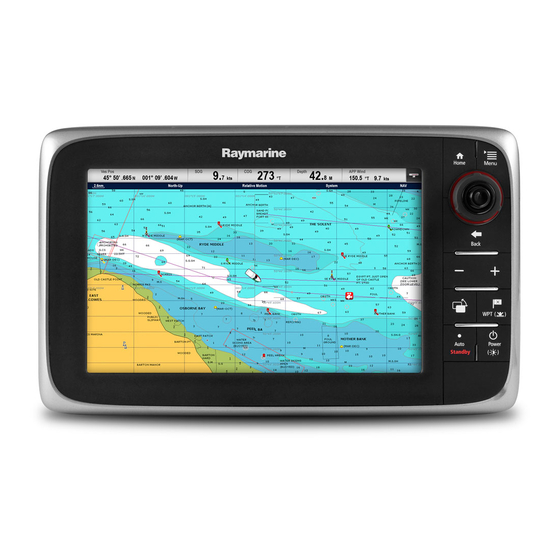
The illustration of the multifunction display below is used throughout this manual and unless otherwise stated can apply to all variants of multifunction display (i.e. New a series, New c Series and New e Series). D12596-1... -
Page 17: Handbook Conventions
2.4 Handbook conventions The following conventions are used throughout this handbook when referring to: Type Example Convention Icons The term "select" is used in procedures involving icons to refer to the action of selecting an on-screen icon, either using touch or physical buttons: •... - Page 18 WPT icons • New a Series • gS Series Throughout this manual the term: Select WPT, refers to pressing the physical WPT button or pressing the onscreen WPT icon. New a Series / New c Series / New e Series...
-
Page 19: Touch And Non-Touch Operations
2.5 Touch and non-touch operations This handbook applies to both touch and non-touch operations. This handbook uses icons to identify whether a particular task is specifically a touch or a non-touch operation. Where a task does not have a touch or non-touch icon then the task can be performed using either. - Page 20 New a Series / New c Series / New e Series...
-
Page 21: Chapter 3 Planning The Installation
3.8 System protocols on page 33 • 3.9 Data master on page 34 • 3.10 New a Series parts supplied on page 34 • 3.11 e7 / e7D Parts supplied on page 35 • 3.12 New c Series and New e Series parts supplied on page 35 •... -
Page 22: System Integration
Third-party NMEA 2000 interfaces. NMEA 2000 (via optional DeviceNet third-party adaptor cables). • 1 x fresh water. • 1 x waste water. • 1 x sewage. • 1 x bait / fish. New a Series / New c Series / New e Series... - Page 23 SeaTalk, SeaTalk , or NMEA 0183. Raymarine • RS130. • Raystar125 GPS. • Raystar125+ GPS (via optional SeaTalk to SeaTalk converter). Instruments — Raymarine As determined by SeaTalk SeaTalk, SeaTalk SeaTalk bus bandwidth • ST70. and power loading. • ST70+.
- Page 24 DSC VHF radio — SeaTalk Note: New a Series requires an Raymarine NMEA 0183 to SeaTalk converter. • Ray260 • Ray260 AIS NMEA 0183: • Ray49 • Ray55 • Ray218 • Ray240 New a Series / New c Series / New e Series...
- Page 25 Additional multifunction SeaTalk (recommended): SeaTalk display(s) — Raymarine • New a Series multifunction displays. • New c Series multifunction displays. • New e Series multifunction displays. • gS Series multifunction displays. Note: You can connect Raymarine multifunction displays using NMEA...
- Page 26 • Navionics Gold+ • Navionics Platinum • Navionics Platinum+ • Navionics Fish'N Chip • Navionics Hotmaps Refer to the Raymarine website (www.raymarine.com) for the latest list of supported chart cards. New a Series / New c Series / New e Series...
-
Page 27: Installation Checklist
3.2 Installation checklist 3.3 System Limits Installation includes the following activities: The following limits apply to the number of system components that can be connected in a Raymarine multifunction display Installation Task system. Plan your system. Component Maximum Obtain all required equipment and tools. -
Page 28: Multiple Data Sources (Mds) Overview
If MDS-compliant software is not available and you do NOT want the system to automatically attempt to resolve data conflicts, any non-compliant product(s) can be removed or replaced to ensure the entire system is MDS-compliant. New a Series / New c Series / New e Series... -
Page 29: Networking Constraints
• External sonar modules should be turned off at the power supply. • All networked New a Series, New c Series and New e Series displays must contain software version 4.xx or later. 2. Wait for the No Sounder Source Available message to be displayed in the Fishfinder application. -
Page 30: Typical Systems
Example: Basic system with sonar variant display SMART SeaT alk / RayNet SeaT alk D12589-1 1. Multifunction display 2. Sonar transducer. 3. Radar scanner. 4. SPX course computer. 5. SeaTalk pilot controller. New a Series / New c Series / New e Series... - Page 31 Example: Basic system with non-sonar variant display SMART SeaT alk / RayNet SeaT alk D12590-1 1. Multifunction display. 2. Sonar module. 3. Sonar transducer. 4. SPX course computer. 5. SeaTalk pilot controller. Example: Expanded system SeaT alk DeviceNet SeaT alk / RayNet SeaT alk / RayNet...
- Page 32 15. Wireless connection. New a Series / New c Series / New e Series...
-
Page 33: System Protocols
3.8 System protocols is generally used to connect a data receiver and a transmitter together, e.g. a compass sensor transmitting heading to a radar display. This information is passed in ‘sentences’, each of which Your Multifunction Display can connect to various instruments and displays to share information and so improve the has a three letter sentence identifier. -
Page 34: Data Master
Multifunction display autopilot. Mounting gasket Sun cover Trunnion bracket kit Documentation pack Power cable 4x Nuts, bolts, spring washers and washers (can be used for either surface or bracket mounting.) New a Series / New c Series / New e Series... -
Page 35: E7 / E7D Parts Supplied
3.11 e7 / e7D Parts supplied 3.12 New c Series and New e Series parts supplied The parts shown below are supplied with the e7 / e7D multifunction display. The parts shown below are supplied with the New c Series and New e Series (Excluding e7 and e7D) multifunction displays. -
Page 36: Tools Required For Installation
5. Spanner for surface mounting or bracket mounting fixings. 6. File. 7. Hole saw for flush mounting (For hole saw size refer to your product’s mounting template). 8. Drill bit for surface mounting or bracket mounting. New a Series / New c Series / New e Series... -
Page 37: Chapter 4 Cables And Connections
4.10 Weather receiver operation with multifunction displays on page 54 • 4.11 SeaTalk connection on page 56 • 4.12 New a Series DSC VHF radio connection on page 56 • 4.13 NMEA 0183 connection on page 57 • 4.14 NMEA 2000 connection on page 58 •... -
Page 38: General Cabling Guidance
Cable shielding Ensure that all data cables are properly shielded that the cable shielding is intact (e.g. hasn’t been scraped off by being squeezed through a tight area). New a Series / New c Series / New e Series... -
Page 39: Connections Overview
4.2 Connections overview Details of the connections available on Raymarine multifunction displays are shown below. e97 / e127 e95 / e125 / e1 65 c97 / c127 c95 / c125 D12249-6 Power / Data SeaTalk SeaTalk / RayNet / RayNet... -
Page 40: Power Connection - New A Series
The display is supplied with a power cable, this can be extended if required. Power cables available For flush mount installations a right angled power cable (not supplied) is available. Cable Part number Notes Right angled power A80221 cable New a Series / New c Series / New e Series... -
Page 41: Power Connection - New C Series And New E Series
(approximately the distance from the battery to the display). To calculate the round trip length, double the figure stated here. Raymarine recommends that all power connections are made via a distribution panel. • All equipment must be powered from a breaker or switch, with Breakers, fuses and circuit protection appropriate circuit protection. - Page 42 Negative (-) bar Circuit breaker Fuse Where possible, connect individual items of equipment to individual circuit breakers. Where this is not possible, use individual in-line fuses to provide the necessary protection. New a Series / New c Series / New e Series...
-
Page 43: Network Connections
SeaT alk / RayNet D12251-1 1. Raymarine network switch. 2. Multifunction display. 3. Raymarine radar scanner. 4. Thermal camera. Note: New a Series displays do not support connection to a thermal camera. Network hardware Item Part number Notes RJ45 SeaTalk E55060... - Page 44 2 SeaTalk / RayNet devices directly to the display. – SR100 Sirius weather receiver. • New a Series and the e7 / e7D displays can connect 1 – Additional compatible Raymarine multifunction displays. SeaTalk / RayNet device directly to the display.
- Page 45 D12254-1 1. Radar extension cable. 2. Radar power and data digital cable. 3. Raymarine network switch (or crossover coupler if connecting radar directly to display). 4. RayNet cable (or RayNet to SeaTalk cable if connecting via crossover coupler). Note: The extension cable connects to the radar scanner.
- Page 46 • Sonar module connection — converts the sonar signals provided by the sonar transducer into data suitable for a marine electronics system. The sonar variant multifunction displays feature a built-in sonar, enabling you to connect the D12256-1 New a Series / New c Series / New e Series...
- Page 47 You can connect a thermal camera to your New c Series or New e Series multifunction displays. Note: New a Series does not support thermal cameras. The camera is usually connected via a Raymarine network switch. If you want to use the optional Joystick Control Unit (JCU) with the camera this must also be connected to the network switch.
- Page 48 Item Description Video cables Multifunction display Video cables are not supplied with the product. Please contact Raymarine network switch your dealer for suitable cables and adaptors. New a Series / New c Series / New e Series...
- Page 49 3. Right angled power cable. multifunction display. When connecting the keypad directly to a New a Series, New c Series or New e Series multifunction display the keypad must be powered separately, using the alternate power connector.
- Page 50 1. Select External Keypad from the External Devices menu: homescreen > Set-up > System Settings > External Devices > External Keypad. 2. Select Clear Pairings. 3. Select Yes to unpair the keypad with the display. New a Series / New c Series / New e Series...
-
Page 51: Gps Connection
4.6 GPS connection 4.7 AIS connection Depending on display variant, your multifunction display may A compatible AIS can be connected using SeaTalk or NMEA include an internal GPS receiver. If required the multifunction 0183. display can also be connected to an external GPS receiver, Connection using SeaTalk using SeaTalk or NMEA 0183. -
Page 52: Fastheading Connection
SmartPilot SPX course computer); or: • Other suitable 12 V power supply. Note: SeaTalk does NOT supply power to multifunction displays and other equipment with a dedicated power supply input. New a Series / New c Series / New e Series... - Page 53 SeaTalk cabling components Description Part No Notes SeaTalk cabling components and their purposes. A06035 SeaTalk 3 m (9.8 ft) backbone Connection / Cable Notes SeaTalk 5 m (16.4 ft) A06036 Backbone cable (various lengths) The main cable carrying data. Spurs backbone from the backbone are used to connect SeaTalk...
-
Page 54: Weather Receiver Operation With Multifunction Displays
• SeaTalk products are connected to SeaTalk via the SeaTalk system data issues and is NOT recommended. Only use one to SeaTalk converter (part number E22158). of the alternative configurations detailed below. New a Series / New c Series / New e Series... - Page 55 SeaTalk to SeaTalk converter (part number E22158). Note: The alternative configurations do not apply to New a Series as there is no NMEA0183 connection. System limitations of alternative configurations • With the exception of heading and rudder position, signals such as Speed, Depth, Position etc.
-
Page 56: Seatalk Connection
5 m (16.4 ft) SeaTalk D286 extension cable 9 m (29.5 ft) SeaTalk D287 extension cable E25051 12 m (39.4 ft) SeaTalk extension cable 20 m (65.6 ft) SeaTalk D288 extension cable New a Series / New c Series / New e Series... -
Page 57: Nmea 0183 Connection
NMEA 0183 devices can be connected to New c Series and New Ite- Cable Input / negative e Series multifunction displays using the power and data cable. Device color Port output Note: New a Series does not support connection of NMEA NMEA Output Positive 0183 devices. device Output Negative Input Positive... -
Page 58: Nmea 2000 Connection
Series multifunction displays. For camera connections to a • Use your SeaTalk backbone and connect each NMEA 2000 New a Series display please refer to the IP camera connection device on a spur, OR section. • connect the display on a spur into an existing NMEA 2000 backbone. -
Page 59: Camera / Video In-Out Connection
New e Series multifunction displays (excluding the e7 / e7D) using the dedicated video in/out connector. Video cables Note: New a Series and New c Series multifunction displays The following video cable is required for the video in / out do not have a dedicated video in/out connector. -
Page 60: Media Player Connection
10. If the pairing code displayed on the multifunction display matches the code displayed on the external media device, With the homescreen displayed: New a Series / New c Series / New e Series... -
Page 61: Bluetooth Remote Control Connection
6. Select Unpair / Forget this device. D12163-2 1. Multifunction display. 2. Bluetooth connection. 3. Raymarine Bluetooth remote control (for example, RCU-3). To use the remote control you must first: • Enable Bluetooth in the System Settings on the multifunction display. - Page 62 2. Select System Settings. 3. Select External Devices. 4. Select Remote Control. 5. Select Customize shortcut key. 6. Select the function that you want to assign to the SHORTCUT key. New a Series / New c Series / New e Series...
-
Page 63: Remote Control Functions
4.19 Remote control functions Bu tto n s Arrow buttons Shortcut button Ra n g e P a ir S e le c t D12051-2 Button Application where function available: Default functions: Chart Radar Fishfinder Weather Homescreen Range / zoom. •... - Page 64 Seconds Note: You will also need to reconnect the RCU-3 as described above if you disable and then re-enable the Bluetooth connection on the multifunction display at any time. New a Series / New c Series / New e Series...
-
Page 65: Wifi Connections
You can use compatible tablet and smartphone devices as a wireless repeat display or remote control for your multifunction display. Raymarine apps allow you to stream and / or control, remotely what you see on your multifunction display to a compatible device, using a Wi-Fi connection. - Page 66 New a Series / New c Series / New e Series...
-
Page 67: Chapter 5 Location And Mounting
Chapter 5: Location and mounting Chapter contents • 5.1 Selecting a location on page 68 • 5.2 Mounting - New a Series on page 69 • 5.3 Mounting - New c Series and New e series on page 71 Location and mounting... -
Page 68: Selecting A Location
D11537-2 This location provides optimal GPS performance (above decks). In this location, GPS performance may be less effective. This location is NOT recommended for GPS antenna. New a Series / New c Series / New e Series... -
Page 69: Mounting - New A Series
Viewing angle considerations D12576-1 As display contrast, color and night mode performance are all affected by the viewing angle, Raymarine recommends you temporarily power up the display when planning the installation, 60º 75º to enable you to best judge which location gives the optimum 60º... - Page 70 Before mounting the unit ensure that you have: • Selected a suitable location. • Identified the cable connections and route that the cables will take. • Attached the front bezel. New a Series / New c Series / New e Series...
-
Page 71: Mounting - New C Series And New E Series
5.3 Mounting - New c Series and New display, ensuring that the clips along the bottom edge of the bezel latch into position. e series Viewing angle D12268-1 e95 / e97 / e125 / e127 / e7 / e7D e165 c95 / c97 c125 / c127 70º... - Page 72 2. Fix the appropriate cutting template supplied with the product, • Identified the cable connections and route that the cables will to the selected location, using masking or self-adhesive tape. take. New a Series / New c Series / New e Series...
- Page 73 • Attach the front bezel. display, ensuring that the clips along the bottom edge of the bezel latch into position. D12274-1 4. Ensure the bezel is correctly aligned with the display, as shown. 5. Apply firm but even pressure to the bezel along the: i.
- Page 74 New a Series / New c Series / New e Series...
-
Page 75: Chapter 6 Getting Started
Chapter contents • 6.1 Display power on page 76 • 6.2 New a Series Controls on page 76 • 6.3 e7 / e7D Controls on page 77 • 6.4 c95 / c97 / c125 / c127 / e95 / e97 / e125 / e127 / e165 Controls on page 77 •... -
Page 76: Display Power
4. You can wake the unit from PowerSave mode at anytime by pressing a physical button on the multifunction display. Note: PowerSave mode is automatically cancelled if an alarm event occurs. New a Series / New c Series / New e Series... -
Page 77: E7 / E7D Controls
6.3 e7 / e7D Controls 6.4 c95 / c97 / c125 / c127 / e95 / e97 / e125 / e127 / e165 Controls D12179-1 Description Functions Touchscreen you can touch the screen to operate many common functions, including all menu operations. D12276-1 Menu Accesses menus. - Page 78 The cursor is context-sensitive. When it is placed over an object such as a waypoint or chart feature, it changes color and a label or information associated with the object is displayed. New a Series / New c Series / New e Series...
-
Page 79: Hybridtouch Overview
(such as rough sea conditions) when it is not appropriate to use the touchscreen. In these situations, Raymarine strongly recommends that you activate the touch lock and use the physical buttons to operate your multifunction display. -
Page 80: Homescreen Overview - Touch Only Displays
1. Press the Home button. Note: The e7 and e7D have a combined Menu and Home button, to access the homescreen press and hold the Menu / Home button for 3 seconds. New a Series / New c Series / New e Series... -
Page 81: System Checks
In order for your GPS receiver and multifunction display to correlate accurately with your paper Note: Raymarine recommends that you check the displayed charts, they must be using the same datum. vessel position in the chart application against your actual proximity to a known charted object. - Page 82 2. Note the position of the object on the radar display. If the sonar module to enable the display's internal sonar option. target is not under the ships heading marker (SHM), there is New a Series / New c Series / New e Series...
- Page 83 Selecting the sonar transducer Panning and tilting, and the thermal image With the fishfinder application displayed: On a touchscreen multifunction display you can pan and tilt the 1. Select Menu. thermal camera image using the touchscreen. 2. Select Set-Up. Move your finger up and down the screen to tilt the camera 3.
-
Page 84: Enabling Autopilot Control
3. Select External Devices. 4. Select Pilot Set-up. 5. Select Pilot control so that On is highlighted. Selecting Pilot control will switch the Autopilot control function on and off. New a Series / New c Series / New e Series... -
Page 85: Pages
2 applications per page. 1. Select Customize. • The New a series and the e7 / e7D can however show up to 4 2. Select Homescreen. application per page if they are sharing the homescreen of a 3. -
Page 86: Applications
User Manual — Opens the English version of the product user manual stored on the display. To open translated user manuals stored on memory card use the Doc Viewer. New a Series / New c Series / New e Series... -
Page 87: Splitscreen Controls
When viewing a splitscreen page you can select the active The keypad will cycle through displays in the order in which application and view it fullscreen on a New a Series or e7 / e7D they were paired. On multi application pages the Range by following the steps below. -
Page 88: Screen Overview
Home On non-touchscreen displays or HybridTouch displays use the Back button. • New a Series — Select the on-screen Home icon to access the homescreen. Close — On displays with a touchscreen you can press the • New c Series — Use the Home button to go back to onscreen X (close) icon to go back to a previous menu. - Page 89 Screen item Description Screen item Description Back Back • Displays with a touchscreen — Select the on-screen • Displays with a touchscreen — Select the on-screen Back icon to go back to the previous menu. Back icon to go back to the previous menu. •...
-
Page 90: Editing Information In Dialogs
Slide the slider Up or control to adjust value Down to adjust value. Auto Press Ok button Select to switch to switch between between Auto and Auto and manual manual adjustment. adjustment. New a Series / New c Series / New e Series... -
Page 91: Editing Numerical Settings
6.17 Editing numerical settings 6.18 Basic touchscreen operations To edit numerical values you can use either the onscreen Placing and moving the cursor using numeric adjust control, onscreen numeric keypad or the Rotary Control on a non-touch or HybridTouch display to increase or touch decrease numeric values. -
Page 92: Databar Status Symbols
AIS unit is switched off, or not connected. Dodge mode is active. AIS unit is in Silent Mode. Fish mode is active. AIS unit is in Silent Mode, with active alarms. Autopilot calibration. New a Series / New c Series / New e Series... -
Page 93: Initial Set Up Procedures
Symbol Description Once your display has been installed and commissioned, Power steering active. Raymarine recommends that you perform an initial set up procedure. Startup wizard Wind Vane mode is active. When you power-up the display for the first time or after a system reset a Startup Wizard is displayed. -
Page 94: Data Master
Designating the data master For systems with 2 or more displays the following task must be performed on the multifunction display that you want to designate as the data master. New a Series / New c Series / New e Series... -
Page 95: Software Updates
You should ensure you have the displays and remote keypads require the update. latest software by regularly checking the Raymarine website for new software. You can identify your multifunction display’s current software version from the Limitations on Use (LoU) splash screen: The software alert is only displayed once per power cycle. - Page 96 New a Series / New c Series / New e Series...
-
Page 97: Chapter 7 Managing Display Data
Chapter 7: Managing display data Chapter contents • 7.1 Memory cards overview on page 98 • 7.2 Inserting a memory card or chart card on page 98 • 7.3 Removing a memory card or chart card on page 99 • 7.4 Saving user data and user settings on page 99 •... -
Page 98: Memory Cards Overview
You can use MicroSD memory cards to archive data (e.g. waypoints and tracks). Note: New a Series displays have 1 card slot, cards must be MicroSD memory cards can be used to archive your data when inserted into New a Series displays with the contacts facing the system capacity is reached. -
Page 99: Removing A Memory Card Or Chart Card
Note: Raymarine recommends that you save your user data and user settings to a memory card on a regular basis. Note: Raymarine strongly recommends that you save settings to a separate memory card, and NOT to a chart card containing cartography. - Page 100 Fish alarm Homescreen Default page configuration Fish alarm depth limit System settings Position mode Shallow depth alarm Text size Deep depth alarm Shared brightness AIS dangerous target alarm Brightness group New a Series / New c Series / New e Series...
- Page 101 Chart application — Cartography settings Data application Application Setting Application Setting Cartography Data overlay cell 1 on / off Data Datapages and content Data overlay cell 1 content Datapage order Data overlay cell 2 on / off Color theme Data overlay cell 2 content Dial color Chart object menu Number of engines...
-
Page 102: Screenshots
4. Select Yes to proceed with the settings and data reset, or is saved. No to cancel. 5. Select the image you want to view. The image will now open. 6. Select Back or Close to close the image. New a Series / New c Series / New e Series... -
Page 103: Chapter 8: Document Viewer Application
Chapter 8: Document viewer application Chapter contents • 8.1 Document viewer overview on page 104 Document viewer application... -
Page 104: Document Viewer Overview
• Find — Allows you to search the document for a specified words. • Fit to Height — Scales the open document to fit the height of the application window. New a Series / New c Series / New e Series... - Page 105 • The first occurrence of the keyword is highlighted. 5. Move the Joystick Down to go to the next occurrence of Note: New a Series and e7 / e7D multifunction displays do the keyword, or not have Range in and Range out button.
- Page 106 New a Series / New c Series / New e Series...
-
Page 107: Chapter 9 Autopilot Control
Chapter 9: Autopilot control Chapter contents • 9.1 Autopilot control on page 108 • 9.2 Pilot Bar on page 110 • 9.3 Pilot Set-up on page 111 • 9.4 Pilot settings on page 111 • 9.5 Autopilot status symbols on page 116 •... -
Page 108: Autopilot Control
The example below shows the Pilot Control dialog options when heading. in track mode. Pilot Control dialog (Auto) The example below shows the Pilot Control dialog options when Auto (locked heading) has been engaged. D12882-1 New a Series / New c Series / New e Series... - Page 109 Enabling autopilot control Disengaging the autopilot from the chart application On all multifunction display variants the autopilot can be Enabling the autopilot control function — SeaTalk and SPX disengaged from the chart application’s menu. SeaTalk autopilots In the chart application with the autopilot engaged: To enable control of your SeaTalk or SPX SeaTalk autopilot 1.
-
Page 110: Pilot Bar
The Pilot Bar is now displayed at the bottom of the screen in all applications whilst the autopilot is engaged. Note: When connected to an Evolution autopilot the Pilot Bar is enabled from the Pilot Set-up page. New a Series / New c Series / New e Series... -
Page 111: Pilot Set-Up
9.3 Pilot Set-up 9.4 Pilot settings The Pilot settings option is available on a data master When connected to an Evolution autopilot the Pilot Set-up page multifunction display when it is integrated with an Evolution is available. autopilot. The Pilot settings enable the setup and commissioning of an Evolution autopilot using a multifunction display. - Page 112 • Power Steer. limits then the alignment of the rudder reference sensor will need to be physically adjusted. • Reverse rudder ref. • Rudder Offset. New a Series / New c Series / New e Series...
- Page 113 Setting the rudder limits • System layout: components and connections (you should have a schematic of the vessel’s autopilot system). On vessels fitted with a rudder reference transducer the rudder limits must be set. The rudder limit is used to set the rudder control.
- Page 114 The rudder limit will be displayed with a message confirming that the rudder limit has been updated. This value can be changed if required. New a Series / New c Series / New e Series...
- Page 115 EV unit to compensate appropriately. If this is the case, the deviation display will indicate a value of 25 degrees or higher. In this scenario, Raymarine highly recommends that the EV unit is moved and re-installed in a location which is subject to less magnetic interference.
-
Page 116: Autopilot Status Symbols
Fish mode is active. 1. Select STANDBY. The alarm is silenced, and the autopilot is disengaged and put in standby mode. Autopilot calibration. Power steering active. Wind Vane mode is active. New a Series / New c Series / New e Series... -
Page 117: Chapter 10 Alarms And Man Over Board Functions
Chapter 10: Alarms and Man over board functions Chapter contents • 10.1 Using Man Overboard (MOB) functions on page 118 • 10.2 Alarms on page 119 Alarms and Man over board functions... -
Page 118: Using Man Overboard (Mob) Functions
1. Press and hold the onscreen WPT / MOB icon for 3 seconds. Silencing the MOB alarm. The MOB alarm can be silenced by following the steps below. With a MOB alarm active: New a Series / New c Series / New e Series... -
Page 119: Alarms
10.2 Alarms Alarms alert you to a situation or hazard requiring your attention. You can set up alarms to alert you to certain conditions, such as collision warnings and temperature limits. Alarms are raised by system functions, and also external equipment connected to your multifunction display. - Page 120 • Fish Depth Limits — Switches depth limits On and Off. • On • Shallow Fish Limit — Specifies the lower value for the Fish Alarm • Off (default) Depth Limit. Shallow Fish Limit New a Series / New c Series / New e Series...
- Page 121 Menu item Description Options • Deep Fish Limit — Specifies the upper value for the Fish Alarm • 2 ft (or equivalent units) to the maximum of the Depth Limit. transducer range Deep Fish Limit • 2 ft (or equivalent units) to the maximum of the transducer range Fuel Manager In the fuel manager alarm options you can switch the low fuel warning...
- Page 122 New a Series / New c Series / New e Series...
-
Page 123: Chapter 11 Dsc Vhf Radio Integration
Chapter 11: DSC VHF radio integration Chapter contents • 11.1 Using a DSC VHF radio with your display on page 124 • 11.2 Enabling DSC VHF radio integration on page 124 DSC VHF radio integration... -
Page 124: Using A Dsc Vhf Radio With Your Display
For information on installing and operating your DSC VHF radio, refer to the handbook that accompanies the radio. The following image shows an example of a distress message displayed on a multifunction display: New a Series / New c Series / New e Series... -
Page 125: Chapter 12 Fuel Manager
Chapter 12: Fuel manager Chapter contents • 12.1 Fuel manager overview on page 126 Fuel manager... -
Page 126: Fuel Manager Overview
Fuel Flow Rate is selected then your multifunction display must remain powered on whilst the engines are running to enable the fuel calculation to be made. 8. Select Back to go back to the Fuel Manager page. New a Series / New c Series / New e Series... - Page 127 Fuel logging The fuel range ring can be displayed graphically in the chart application and indicates an estimated range that can be You must ensure all fuel fills are recorded using the fuel reached with the: manager. From the fuel manager page: •...
- Page 128 New a Series / New c Series / New e Series...
-
Page 129: Chapter 13 Ais Function
Chapter 13: AIS function Chapter contents • 13.1 AIS overview on page 130 • 13.2 AIS prerequisites on page 131 • 13.3 AIS context menu on page 131 • 13.4 Enabling AIS on page 132 • 13.5 Displaying AIS vectors on page 132 •... -
Page 130: Ais Overview
AIS equipment. Therefore, you should not assume that your multifunction display will show ALL vessels in your area. Due prudence and judgement should be exercised. AIS should be used to complement radar, NOT substitute it. New a Series / New c Series / New e Series... -
Page 131: Ais Prerequisites
13.2 AIS prerequisites 13.3 AIS context menu You must have suitable AIS hardware connected to your The AIS function includes a context menu which provides AIS multifunction display to make use of the AIS functionality. target information and menu items. In order to run AIS, you will need: •... -
Page 132: Enabling Ais
Note: The same target vector and safe zone settings apply 3. Select AIS Targets so that On is highlighted. to both radar MARPA and AIS targets. Selecting AIS Targets will switch AIS between On and Off. New a Series / New c Series / New e Series... -
Page 133: Ais Status Symbols
13.6 AIS status symbols 13.7 AIS silent mode AIS status is indicated by a symbol in the databar. AIS silent mode enables you to disable AIS transmissions AIS silent mode enables you to disable the transmitting functions Symbol Description of your AIS equipment. This is useful when you do not want to AIS unit is switched on and operating. -
Page 134: Ais Target Symbols
Search and rescue SARTS target transponders (SARTS) target Search and rescue SARS target aircraft (SARS) target Military and law Only displayed when enforcement target connected to approved STEDS-EAIS AIS hardware. New a Series / New c Series / New e Series... -
Page 135: Viewing All Ais Targets
13.10 Viewing all AIS targets 13.11 Using AIS to avoid collisions You can use the AIS safe zone and safety message functions to • From the Chart application with only the AIS overlay enabled go to: Menu > AIS Options. help you avoid collisions with other vessels and objects. - Page 136 2. Select AIS Data so that On is highlighted. Selecting AIS Data will switch between AIS data On and Off. The Safety critical AIS data will now be displayed next to the target in the application. New a Series / New c Series / New e Series...
-
Page 137: Marpa & Ais Options
13.12 MARPA & AIS options Parameter Description Options Vector Length The length of the vector lines displayed depends • 0.5 min on the distance that an AIS target travels in the • 1 min time period that you specify for this setting. •... -
Page 138: Ais Alarms
1. Select Menu. 2. Select Track Targets. 3. Select MARPA & AIS Options. 4. Select Buddy Tracking . Selecting Buddy Tracking will switch between buddy tracking On and Off. New a Series / New c Series / New e Series... - Page 139 Adding a vessel to your buddy list 2. Select Buddy Data so that On is highlighted. Selecting Buddy Data will switch data between On and Off. In the chart or radar application: The Buddy MMSI and Name will now be displayed next to the 1.
- Page 140 New a Series / New c Series / New e Series...
-
Page 141: Chapter 14 Waypoints, Routes And Tracks
Chapter 14: Waypoints, Routes and Tracks Chapter contents • 14.1 Waypoints on page 142 • 14.2 Routes on page 147 • 14.3 Tracks on page 150 • 14.4 Waypoints, routes and tracks storage capacity on page 152 Waypoints, Routes and Tracks... -
Page 142: Waypoints
For active waypoints the following menu items are available: • Stop Goto • Restart XTE Showing and hiding waypoint groups / symbols From the chart or radar application: • Advance Waypoint New a Series / New c Series / New e Series... - Page 143 • any application — by pressing the WPT button (New c Series A confirmation pop up message is displayed. and New e Series) or the WPT icon (New a Series). This 3. Select Ok to place the waypoint, or Edit to edit the waypoint displays the Waypoints menu.
- Page 144 With the Waypoint List displayed: 1. Select the waypoint you want to edit. The waypoint options dialog is displayed. 2. Select Edit Waypoint. 3. Select the field you want to edit. D11765-2 New a Series / New c Series / New e Series...
-
Page 145: Moving Waypoints
4. Use the on-screen keyboard to make the changes, then Symbol Type Symbol Type select the on-screen keyboard's SAVE button. Trawler Tree Editing a waypoint using the context menu Triangle Wreck 1. Select the waypoint. The waypoint context menu is displayed. 2. - Page 146 • accessed via the chart application: Menu > My Data > Waypoint And Group Options, or • accessed from any application: WPT > Waypoint And Group Options 1. Select Select Default Group. A list of groups is displayed. New a Series / New c Series / New e Series...
-
Page 147: Routes
14.2 Routes 1. Select and hold a location on screen. The chart context menu is displayed. A route is a series of waypoints typically used to assist with 2. Select Build Route. passage planning and navigation. The build route menu is displayed. - Page 148 4. Select Edit to change the name and line color of the created route. D11751-2 There are a number of ways to select the follow route option: • Using a stored route within the route list. New a Series / New c Series / New e Series...
- Page 149 • From a selected waypoint or any leg within a route. You can also follow any route in reverse order. Following a stored route From the chart application: 1. Select Menu. 2. Select Navigate. 3. Select Follow Route. The Route list is displayed. 4.
-
Page 150: Tracks
A track is an on-screen trail that shows the passage you have 1. Position the cursor over the waypoint you want to move. taken. This trail is made up of a series of track points which are created automatically. You can save the track to create a The waypoint context menu is displayed. - Page 151 • Auto— The track interval is automatically set (Auto will • Erase a track. minimize track points whilst maintaining correlation • Create a route from a track. between the track and the actual path followed). • Show or hide a track on the chart (only available from the •...
-
Page 152: Waypoints, Routes And Tracks Storage Capacity
• 3000 Waypoints points • 100 waypoint groups Routes • 150 routes, each consisting of up to 50 waypoints. Tracks • 15 tracks, each consisting of up to 10000 track points. New a Series / New c Series / New e Series... -
Page 153: Chapter 15 Chart Application
Chapter 15: Chart application Chapter contents • 15.1 Chart application overview on page 154 • 15.2 Chart ranging and panning on page 155 • 15.3 Vessel position and orientation on page 156 • 15.4 Chart views on page 158 • 15.5 Chart context menu on page 159 •... -
Page 154: Chart Application Overview
15.1 Chart application overview • If you have a Raymarine GPS receiver using NMEA0183, or a third-party GPS receiver, you must correlate it separately. The chart application provides an electronic chart with passage It may be possible to use your multifunction display to correlate planning and navigation features. -
Page 155: Chart Ranging And Panning
• Enable Wi-Fi on your tablet / smartphone. and disabled from the homescreen: • Select the Raymarine Wi-Fi connection from the list of Customize available Wi-Fi networks on your tablet / smartphone. > Display Preferences >... -
Page 156: Vessel Position And Orientation
Whilst motion mode is active, as your vessel moves, the chart is redrawn to keep the vessel on-screen. The 3 motion modes are: • Relative Motion (default) • True Motion • Auto Range. New a Series / New c Series / New e Series... - Page 157 Auto Range Note: In the 3D chart view, only Relative Motion mode is available. The current motion mode applies to the active instance of the chart application. When you pan the chart the motion mode is no longer active. This is indicated in the status bar by brackets around the motion mode —...
-
Page 158: Chart Views
Range in — select icon to range in (Touchscreen displays only). Cartographic objects — Level of cartographic objects is determined by the cartography menu accessed from: Homescreen > Set-up > Cartography Menu. New a Series / New c Series / New e Series... -
Page 159: Chart Context Menu
15.5 Chart context menu ii. HybridTouch or Touch only displays — Swipe your finger up or down across the screen to adjust the pitch. The Chart context menu provides the cursors positional data D11755-1 and shortcuts to menu options. 4. To adjust the rotation: i. -
Page 160: My Data Options
• Build Route — Provides options to build a route. Refer to Chapter 14 Waypoints, Routes and Tracks for further details. New a Series / New c Series / New e Series... -
Page 161: Measuring Distances And Bearings
15.8 Measuring distances and 15.9 Chart vectors bearings Chart vectors display indicators for heading, COG, wind direction and tide direction. You can use the databar and context menu information you can use the measure function to measure distances in the chart A range of vector graphics can be displayed in the chart application. -
Page 162: Current Information
5. To set the animation date to the current date select Today. 6. To set the animation date to 24 hours previous to the current date select Previous Day. New a Series / New c Series / New e Series... -
Page 163: Tide Information
15.11 Tide information Tide graphs Tide graphs provide a graphical view of tidal activity. Animated tide information The electronic charts may allow animation of the tide information tide stations. Animated tide information is available in the chart application wherever a diamond-shaped symbol with a "T" is displayed: This symbol identifies tide stations and the availability of tide information for the location. -
Page 164: Chart Object Information
A list of chart object types is displayed. 3. Select Port (search by name) from the list. The on–screen keyboard is displayed. 4. Use the on-screen keyboard to enter the desired port name. New a Series / New c Series / New e Series... -
Page 165: Chart Presentation
15.13 Chart presentation Overlays The chart has a number of overlays providing different kinds of The chart has a number of presentation options which affect the display and information. level of detail, types of objects and how the Chart application appears onscreen. - Page 166 When synchronization is switched on: • The radar range in all radar windows changes to match the chart scale. • ‘Sync’ is indicated in the top left-hand corner of the chart window. D11766-2 New a Series / New c Series / New e Series...
- Page 167 Range rings give you an incremental representation of distance Fuel range rings from your vessel to help you judge distances at a glance. The The fuel range ring gives an estimated range that can be rings are always centred on your vessel, and the scale varies reached with the estimated fuel remaining on-board.
- Page 168 If the chart card does NOT contain bathymetric data the chart reverts to the default NAV (navigation) data. Note: Fish mode is not suitable for navigation. Selecting fish mode From the chart application: 1. Select Menu. New a Series / New c Series / New e Series...
-
Page 169: Selecting The Cartography Set-Up Menu
15.14 Selecting the cartography set-up menu From the Homescreen: 1. Select Set-up. 2. Select Cartography. The cartography menu options are displayed. Chart application... -
Page 170: Cartography Set-Up Menu Options
• Blue Deep Water From setting) Hide Rocks Determines whether rocks are displayed in the chart application. • Off (default) • On New a Series / New c Series / New e Series... - Page 171 Menu item Description Options Nav. Marks Determines whether navigation marks are displayed on the chart: • Off • On (default) • Off — navigation marks are NOT displayed. • On — navigation marks are displayed. Nav. Mark Symbols Determines which set of navigation mark symbols is used — •...
- Page 172 New a Series / New c Series / New e Series...
-
Page 173: Chapter 16 Radar Application
Chapter 16: Radar application Chapter contents • 16.1 Radar overview on page 174 • 16.2 Radar scan speed on page 175 • 16.3 Radar scanner status symbols on page 175 • 16.4 Radar range and image quality on page 176 •... -
Page 174: Radar Overview
Auto / Coastal / Manual Manual Manual Offshore (0-100%) (0-100%) (0-100%) / Manual (0-100%) Auto Mode: Buoy Auto Mode: Harbor Auto Mode: Offshore Auto Mode: Coastal Auto Mode: Bird New a Series / New c Series / New e Series... -
Page 175: Radar Scan Speed
When you return to transmit The speed option requires a 48 RPM compatible Raymarine HD mode, the magnetron does not need to radome or Raymarine SuperHD open array radar scanner. -
Page 176: Radar Range And Image Quality
(normally below 3 nm), and in particular with larger objects. Side lobe echoes form either arcs on the radar screen similar to range rings, or a series of echoes forming a broken arc. New a Series / New c Series / New e Series... - Page 177 Blind Sectors Obstructions such as funnels and masts near the radar antenna may obstruct the radar beam and cause radar shadows or ‘blind sectors’. If the obstruction is relatively narrow, there will be a reduction of the beam intensity, though not necessarily a complete cut-off.
-
Page 178: Radar Display Overview
HD or SuperHD radar scanner, stronger target returns show as different colors from a range of 256 colors, providing better clarity. Be aware that the size of a target on screen New a Series / New c Series / New e Series... -
Page 179: Dual Range Radar Operation
16.6 Dual range radar operation is dependent on many factors and may not necessarily be proportional to its physical size. Nearby objects may appear to The Dual Range radar function enables you to view 2 ranges at be the same size as distant larger objects. the same time in separate windows. -
Page 180: Radar Mode And Orientation
When heading data becomes available once more, North-Up mode is reinstated. Note: It is not possible to select Head Up mode when the motion mode is set to True. New a Series / New c Series / New e Series... - Page 181 Course-Up The default motion mode is “Relative”, with center offset. True Motion (TM) When the motion mode is set to True, fixed radar targets maintain a constant position and moving vessels (including your vessel) travel in true perspective to each other and to fixed landmasses on the screen.
-
Page 182: Radar Tuning: On-Screen Gain Controls
4. Adjust the slider bar to the required setting. 5. The slider bar will auto dismiss, or you can select the on-screen icon again to close the slider bar. New a Series / New c Series / New e Series... -
Page 183: Radar Adjustments: Hd And Superhd Scanners
Adjusting radar preset gain 1. Select Menu. Raymarine strongly recommends the use of the preset gain 2. Select Adjust Gain <Mode>, where <Mode> shall be the modes to achieve optimum results. However if required manual Auto Gain mode already selected. - Page 184 4. Adjust the Power Boost slider bar control to the appropriate setting (between 0 and 100%), or 5. Select the Auto box so that a tick is placed in the box for automatic boost control. New a Series / New c Series / New e Series...
-
Page 185: Radar Adjustments: Non-Hd Digital Radomes
Raymarine • Coastal — accounts for the slightly higher strongly recommends the use of these presets levels of sea clutter you might encounter to achieve optimum results. -
Page 186: Radar Presentation Menu Options
Show/Hide in the radar application. • Show • Hide Waypoint Name This menu item allows you to show or hide waypoint names in the radar • Show application. • Hide New a Series / New c Series / New e Series... - Page 187 Function Description Options Databoxes Set-up This menu item contains a sub-menu which enables you to turn on and select Data Cell 1 & 2 information to display in data cells located on the bottom left of the radar • On application (Data cells will be displayed in all radar windows).
- Page 188 A list of wake time periods id displayed: • 10 sec • 30 sec • 1 min • 5 min • 10 min 6. Select the required time period. New a Series / New c Series / New e Series...
-
Page 189: Using Radar To Measure Distances, Ranges, And Bearings
16.12 Using radar to measure Measuring using VRM/EBL distances, ranges, and bearings Variable Range Markers (VRM) A Variable Range Marker (VRM) is a circle centred on your When you are using the radar application, you can measure vessel’s position and fixed with respect to the heading mode. distances, ranges and bearings in a variety of ways. - Page 190 3. Select the desired location for the center position. The VRM/EBL is placed at the new location. Creating a floating VRM/EBL on the radar display From the radar application with a VRM/EBL already created: New a Series / New c Series / New e Series...
-
Page 191: Using Radar To Track Targets And Avoid Collisions
15. Select Ok to close the numeric adjust control. MARPA will perform. For the best heading data, a Raymarine 16. Select Bearing: . SMART heading sensor or a gyro-stabilized autopilot is required. - Page 192 • Slew thermal camera (Only available when thermal camera present for several scans, the radar locks-on to the target, and is connected and operating.) the symbol changes to “safe target” status. New a Series / New c Series / New e Series...
- Page 193 Cancelling a MARPA target using the MARPA context menu ii. Select On to display the CPA graphic while the target is being tracked. From the radar application: iii. Select Off to hide the CPA graphic. 1. Select the relevant target. 3.
-
Page 194: Radar Set-Up Menu
5. Adjust the slider bar control to the appropriate setting, or 1. Select Menu. 6. Select the Auto box so that a tick is placed in the box for 2. Select Radar Set-up. automatic tuning. 3. Select Tune Adjust. New a Series / New c Series / New e Series... -
Page 195: Resetting The Radar
16.15 Resetting the radar To reset radar settings to defaults follow the steps below: From in the radar application: 1. Select Menu. 2. Select Radar Set-up. 3. Select Advanced. 4. Select Reset Advanced. A confirmation pop up message is displayed. 5. - Page 196 New a Series / New c Series / New e Series...
-
Page 197: Chapter 17 Fishfinder Application
Chapter 17: Fishfinder application Chapter contents • 17.1 How the fishfinder works on page 198 • 17.2 Raymarine sonar modules on page 198 • 17.3 Traditional sonar technology on page 199 • 17.4 CHIRP technology on page 199 • 17.5 Fishfinder introduction on page 200 •... -
Page 198: How The Fishfinder Works
/ e97 / e127 (internal sonar) ClearPulse measure water temperature and/or speed. Note: The Fishfinder application menu options and settings will differ depending on the type of sonar module in use. New a Series / New c Series / New e Series... -
Page 199: Traditional Sonar Technology
17.3 Traditional sonar technology 17.4 CHIRP technology Traditional sonar uses a single carrier frequency or carrier wave CHIRP sonars use a swept frequency 'CHIRP' signal which can for the sonar ping. The sonar works by measuring the time distinguish between multiple close targets, this enables the sonar it takes the ping echo to return to the transducer to determine to display multiple targets instead of large combined targets that target depth. -
Page 200: Fishfinder Introduction
• The bottom together with any bottom structure such as reefs and shipwrecks etc. • Target images indicating fish. • A status bar noting the frequency and gain settings. • The bottom depth. New a Series / New c Series / New e Series... -
Page 201: Transducer Bandwidth
17.6 Transducer bandwidth 17.7 The sonar image The fishfinder application displays the fishfinder frequency, Interpreting the bottom using sonar center frequency or CHIRP mode depending on the connected It is important to understand how to correctly interpret the bottom sonar module and transducer. structure represented on-screen. -
Page 202: Fishfinder Presets
From the fishfinder application: 1. Select Menu. 2. Select Set-up. 3. Select Reset Presets to Default. A confirmation pop-up is displayed. 4. Select Yes to confirm reset, or No to cancel. New a Series / New c Series / New e Series... -
Page 203: Dual / Single Frequency Fishfinder
17.9 Dual / Single frequency fishfinder 17.10 Non-CHIRP (traditional) sonar module frequency controls Dual frequency operation allows the sonar to operate and display 2 frequencies simultaneously. If the preset mode that The frequency of the sonar determines the width of the sonar you are using has two frequencies configured, you can view beam, the depth to which the signals will penetrate and the either one or both of those frequencies in separate windows. -
Page 204: Chirp Sonar Module Frequency Controls
3. Select Freq 1 or Freq 2 as required. 4. Select the required frequency: Example of Frequency setting menu when connected to a CHIRP sonar module. D12573-1 1. Non-CHIRP modes 2. CHIRP modes. New a Series / New c Series / New e Series... - Page 205 Frequency adjustment (CHIRP sonar module in non-CHIRP mode) When using a CHIRP sonar module in CHIRP mode (Low Chirp, Med Chirp or High Chirp) the frequency cannot be adjusted. When using a CHIRP sonar module in a non-Chirp mode (e.g. 50 kHz or 160 kHz) the frequency at which the transducer is transmitting can be adjusted.
-
Page 206: Fishfinder Display Modes
The manual zoom factor dialog is displayed. 4. Select A-Scope to display a list of A-Scope modes. 6. Adjust the setting to the required value. 5. Select the required A-Scope mode. New a Series / New c Series / New e Series... -
Page 207: Fishfinder Range
17.13 Fishfinder range Bottom Lock The Bottom Lock function applies a filter to flatten the image of The Range and Range Shift functions enable you to change the the seabed and make any objects on or just above it easier to range of depth displayed by the fishfinder. -
Page 208: Fishfinder Sensitivity Settings
When using a non-CHIRP sonar module, from the fishfinder application: 1. Select Menu. 2. Select Sensitivity Settings. 3. Select Gain Mode. A list of available auto gain modes is displayed: • Cruising (Low) New a Series / New c Series / New e Series... - Page 209 TVG adjustment can be made automatically or manually. Adjusting fishfinder gain manually using on-screen TVG Presets and auto settings controls When connected to a Raymarine CHIRP sonar module 3 preset Touchscreen multifunction displays provide on-screen access to TVG options are available: the gain controls.
- Page 210 4. Adjust the color threshold to the required setting. 5. Select Ok to confirm setting and close the numeric adjust When in manual mode the slider bar control is shown: control. New a Series / New c Series / New e Series...
-
Page 211: Fishfinder Presentation Options
Setting the frequency for power mode horizontal lines • Off indicating depth are When connected to a Raymarine CHIRP sonar module, the displayed. power mode for frequency 1 and frequency 2 can be changed independently or both at the same time. If connected to a... -
Page 212: Depth And Distance With The Fishfinder
4. Select Place Marker. 5. Select the location you want to place the marker. Note: Once placed you can move the marker by selecting Move Marker from the fishfinder context menu. New a Series / New c Series / New e Series... -
Page 213: Fishfinder Scrolling
17.17 Fishfinder scrolling Fishfinder marker context menu The fishfinder marker includes a context menu which provides The fishfinder image scrolls from right to left. You can pause the marker information and menu items. scrolling or adjust the scroll speed, to ease placing of waypoints or VRMs on-screen. -
Page 214: Fishfinder Waypoints
4. Adjust the setting to the required value. 5. Select Ok to confirm the new value and close the numeric adjust control. Note: The Shallow Limit cannot be set to greater than the Deep Limit. New a Series / New c Series / New e Series... -
Page 215: Sounder Set-Up Menu Options
17.20 Sounder set-up menu options This section describes the settings you can change using the sounder set up menu: (Menu > Set-up > Sounder Set-up). The set up menu contains settings that are likely to be changed infrequently. Menu Item Description Options Internal Sounder... -
Page 216: Transducer Set-Up Menu Options
Speed Offset Offset applied to the speed log. • 0 to 100% Temperature Offset Offset applied to the temperature transducer value. • –9.9 to +9.9 °F — or equivalent units New a Series / New c Series / New e Series... - Page 217 Fishfinder Transducer Calibration Your fishfinder transducer must be calibrated correctly to achieve accurate depth readings. The multifunction display receives the image from a sonar module which processes sonar signals from a transducer mounted in the water. If the transducer is equipped with a speed paddle wheel and temperature-sensing thermistor, the sonar module calculates speed and temperature.
-
Page 218: Resetting The Sonar
2. Select Menu from the side menu. 3. Select Set-up. 4. Select Sounder Set-up. 5. Select Sonar reset. 6. Select Yes to confirm. The unit will now be reset to factory default settings. New a Series / New c Series / New e Series... -
Page 219: Chapter 18 Data Application
Chapter 18: Data application Chapter contents • 18.1 Data application overview on page 220 • 18.2 Selecting datapages using touch on page 221 • 18.3 Selecting datapages on page 222 • 18.4 Customizing the data application on page 222 • 18.5 Resetting minimum and maximum readings on page 229 •... -
Page 220: Data Application Overview
• Starboard Coolant temperature • Sea Temperature • Set & Drift • Starboard RPM • Sea Temperature • Total Fuel • Local time • Trim tabs • Rudder • SOG New a Series / New c Series / New e Series... -
Page 221: Selecting Datapages Using Touch
Datapage 7 inch displays and below 9 inch displays and above 18.2 Selecting datapages using Fuel • Port Coolant temperature touch • Port Oil Pressure You can scroll through all available pages using the touchscreen. • Port Fuel remaining • Starboard Coolant temperature •... -
Page 222: Selecting Datapages
7. Repeat steps 3 to 6 for all the data items you want to change. Renaming a datapage From the data application: 1. Select Menu. 2. Select Edit Page. 3. Select Rename Page. The on screen keyboard is displayed. New a Series / New c Series / New e Series... - Page 223 Setting maximum engine RPM 4. Enter the new name for the datapage. 5. Select SAVE. You can set the maximum RPM range to display on the RPM data item. Adding a new datapage From the data application: You can add your own customized datapages to the data 1.
- Page 224 From the Data application: 1. Select Menu. 2. Select Units Set-up. 3. Select the type of measurement you want to change. 4. Select the new unit of measure. New a Series / New c Series / New e Series...
- Page 225 List of data items Depending on connected devices the categories of data available to display in the data application, data overlay, databar, and expanded databar are shown below. The following table shows the data items available by category. Data Category Description Data Item Digital...
- Page 226 For example, air temperature. Air Temperature Minimum Air Temperature Maximum Air Temperature Drift Set & Drift Apparent Wind Chill True Wind Chill Humidity Dew Point Sunset / Sunrise Water Temperature New a Series / New c Series / New e Series...
- Page 227 Data Category Description Data Item Digital Dials* Graphical* Minimum Water Temperature Maximum Water Temperature GPS-related data. Vessel Position For example, vessel position. COG & SOG Maximum SOG Average SOG Heading Heading-related data. Heading For example, locked heading. Heading and Speed (Data application only.) Locked Heading Locked Heading Error...
- Page 228 Local Time and Date Wind Wind-related data. For example, VMG (Velocity Made Good) Maximum AWA to Windward. Minimum AWA Maximum AWS Minimum AWS Maximum TWA Minimum TWA Maximum TWS New a Series / New c Series / New e Series...
-
Page 229: Resetting Minimum And Maximum Readings
Data Category Description Data Item Digital Dials* Graphical* Minimum TWS TWA & TWS TWA (CH) and TWS TWA and VMG AWA & AWS AWA (CH) and AWS AWA and VMG AWA and TWA Beaufort Cardinal Wind Ground Wind GWD & GWS GWD and Beaufort None Note: *Dials and graphical representations are only available from the Data application. - Page 230 New a Series / New c Series / New e Series...
-
Page 231: Chapter 19 Thermal Camera Application - Pan And Tilt Cameras
Chapter 19: Thermal camera application — Pan and tilt cameras Chapter contents • 19.1 Thermal camera application overview on page 232 • 19.2 Thermal camera image on page 232 • 19.3 Controls overview on page 233 • 19.4 Camera control on page 234 •... -
Page 232: Thermal Camera Application Overview
Scene preset mode for night conditions. Scene preset mode for daytime conditions. Scene preset mode for night docking. Scene preset mode for identifying people or objects in the water. New a Series / New c Series / New e Series... -
Page 233: Controls Overview
Icon Description Rear-view mode — image is flipped horizontally. The thermal camera application is available on compatible Raymarine multifunction displays and systems. It includes controls for the thermal camera. Zoom setting: 2x zoom. Rotary control Zoom image in / out. -
Page 234: Camera Control
3. Use the Surveillance menu item to select the On or Off can switch between x2 and x4 magnification. option, as appropriate. New a Series / New c Series / New e Series... - Page 235 • Medium • Fast 5. Select the required option. Thermal camera stabilization The Raymarine T470SC and T473SC thermal cameras includes a mechanical stabilization feature. The mechanical stabilization feature improves image stability by compensating for vessel motion and keeping the camera aimed at the point of interest.
-
Page 236: Image Adjustments
With the thermal camera application displayed: 2. Select Image Options. 1. Select Menu. 3. Use the Colour menu item to switch between the available 2. Select Image Options. color palettes, as appropriate. New a Series / New c Series / New e Series... - Page 237 3. Use the Image Type menu item to switch between IR and 4. Adjust the value to the required setting. Visible Light views, as appropriate. This value will adjust the camera’s offset position to port or starboard. Thermal camera rear view mode Enabling / disabling automatic slew to cue The rear view mode flips the video image horizontally, providing From the thermal camera application:...
-
Page 238: Pan And Tilt Camera - New Camera Interface
• Stabilization Mode • Point Mode • Ball Down Mode • High Power Standby • High Power Torque • JCU Icon • PC Icon • Restore Factory Defaults • Calibrate Platform New a Series / New c Series / New e Series... - Page 239 Camera Set-up menu Set Home Position Sets the camera’s current position as the Camera Home position. Slew Settings Provides automatic slew options and camera • Auto Slew to MOB alignment settings. • Auto Slew to dangerous AIS target • Auto Slew to dangerous MARPA target •...
- Page 240 If options are different than listed above please refer to the manual that accompanied your thermal camera and / or the installation and operations handbook which accompanied your multifunction display. New a Series / New c Series / New e Series...
-
Page 241: High Power And High Torque Modes
19.7 High power and high torque modes Single Camera State Camera setting Dual payload payload Standby • High Power Mode 22 W 17.4 W • High Torque Mode Standby • High Power Mode 7.4 W • High Torque Mode • High Power Mode 13 W 13 W Standby... -
Page 242: Pan And Tilt Camera - Old Camera Interface
If options are different than listed above please refer to the manual that accompanied your thermal camera and / or the installation and operations handbook which accompanied your multifunction display. Note: It may be possible to update your camera to the new camera interface. Please contact your Raymarine dealer for details. OSD menu options... - Page 243 Surveillance mode menu System Setup Settings to optimize operation for this particular system / installation. Menu item / Description Settings / Operation About / Help Helpful information and restore to factory defaults setting. Scan Width This setting determines the distance that the camera pans left and right when in surveillance Exit Cancels on-screen menu.
- Page 244 Surveillance Mode The USER button will toggle Surveillance mode on and off. Point Mode The USER button will toggle Point Mode on and off. Exit Returns to the main menu. New a Series / New c Series / New e Series...
-
Page 245: Chapter 20 Thermal Camera Application - Fixed Mount Cameras
Chapter 20: Thermal camera application — fixed mount cameras Chapter contents • 20.1 Thermal camera application overview on page 246 • 20.2 Thermal camera image on page 246 • 20.3 Controls overview on page 247 • 20.4 Camera control on page 248 •... -
Page 246: Thermal Camera Application Overview
Scene preset mode for daytime conditions. Scene preset mode for night docking. Scene preset mode for identifying people or objects in the water. Rear-view mode — image is flipped horizontally. Zoom setting: 2x zoom. New a Series / New c Series / New e Series... -
Page 247: Controls Overview
20.3 Controls overview Icon Description Zoom setting: 4x zoom. The thermal camera application is available on compatible Raymarine multifunction displays and systems. It includes controls for the thermal camera. Single active controller on network. Rotary control Zoom image in / out. -
Page 248: Camera Control
Changing the thermal camera color mode With the thermal camera application displayed: 1. Select Menu. 2. Select Image Options. 3. Use the Colour menu item to switch between the available color palettes, as appropriate. New a Series / New c Series / New e Series... - Page 249 Thermal camera reverse video You can reverse the polarity of the video image to change the appearance of objects on-screen. The reverse video option (video polarity) switches the thermal image from white-hot (or red-hot if the color mode setting is active) to black-hot.
-
Page 250: Fixed Mount Camera Menu
• Off mode. With the setting enabled the camera will consume more power, but will help ensure that the camera is held in place in rough seas. New a Series / New c Series / New e Series... - Page 251 JCU Icon Shows or hides the on-screen JCU connected • On (default) icon. • Off PC Icon Shows or hides the on-screen PC connected icon. • On (default) • Off Restore Factory Defaults Enables you to restore the camera’s settings to factory default values.
- Page 252 New a Series / New c Series / New e Series...
-
Page 253: Chapter 21 Camera Application
Chapter 21: Camera application Chapter contents • 21.1 Camera application overview on page 254 • 21.2 Camera cycling on page 255 • 21.3 Naming camera / video feeds on page 255 • 21.4 Adjusting the video image on page 256 •... -
Page 254: Camera Application Overview
Changing the camera / video feed You can view a camera or a video feed which is connected On a New a Series or New e Series display, if more than 1 directly to your multifunction display using the video input(s), or feed is available you can change which feed is displayed on IP camera feeds which are available on your network. -
Page 255: Camera Cycling
21.2 Camera cycling 21.3 Naming camera / video feeds When multiple camera / video feeds are available the camera To help distinguish between camera feeds each feed can be application can be set up to automatically cycle through the named. available feeds at a specified time interval. -
Page 256: Adjusting The Video Image
3. Select Contrast, Brightness, or Color, as appropriate. 3. Select Aspect ratio so that 4:3 or 16:9 is selected as The numeric adjust control is displayed. required. 4. Adjust the level to the required setting. New a Series / New c Series / New e Series... -
Page 257: Selecting A Location To Store Recordings
Video files stored on internal storage are saved in Internal > User Data > Video files. Video files stored on memory card are saved in SD Card # > Raymarine > Video files. 5. Select the Video file. The file options dialog is displayed. -
Page 258: Taking Photos
3. Select Timer. 4. Select Time Delay. A list of time intervals is displayed: • 5 s • 10 s • 30 s 5. Select a time interval from the list. New a Series / New c Series / New e Series... -
Page 259: Viewing Photos
9. Select Delete to delete the photo. Taking a photo using a remote control To take a photo using a Raymarine wireless remote control as the trigger follow the steps below. If saving to a memory card ensure that a memory card with sufficient space is inserted into the relevant card reader slot. -
Page 260: Onscreen Icons
1. Select the Record icon to start recording. 2. Select the Stop recording icon to stop the recording. 3. Select the Take Photo icon to capture a still image. New a Series / New c Series / New e Series... -
Page 261: Chapter 22 Fusion Link Application
Chapter 22: Fusion link application Chapter contents • 22.1 Fusion link overview on page 262 • 22.2 Media sources on page 263 • 22.3 Browsing music on page 265 • 22.4 Selecting shuffle and repeat functions on page 265 • 22.5 Adjusting volume levels for each zone on page 266 •... -
Page 262: Fusion Link Overview
• Mute and Unmute the volume. • Adjust the tone controls (Bass, Middle, and Treble). • Skip backwards and forwards through tracks. • Scan backwards and forwards through the current track. New a Series / New c Series / New e Series... -
Page 263: Media Sources
22.2 Media sources The layout and controls available are determined by the selected media source. iPod D12748-1 Album artwork. Track title. Artist. Track progress. Track number. D12750-1 Album title. Time elapsed. Title. Menu options available for iPods are as follows: Chapter. - Page 264 Note: The Fusion head unit must be used to control a satellite receiver connected to a fusion media system. Current track information and channel details are displayed on the Fusion application. New a Series / New c Series / New e Series...
-
Page 265: Browsing Music
22.3 Browsing music 22.4 Selecting shuffle and repeat functions You can browse the music available on your connected iPod or USB device. You can set the Fusion link application to repeat the selected From the Fusion link application: folder or to shuffle the play order. 1. -
Page 266: Adjusting Volume Levels For Each Zone
3. The volume controls on the main screen will now control the volume level of the selected zone. Note: Adjusting the All Zones level will adjust all of the zones at the same time. New a Series / New c Series / New e Series... -
Page 267: Adjusting The Tone Controls
22.7 Adjusting the tone controls 22.8 Selecting the system to control The Bass, Middle, and Treble tone controls can be adjusted. Where more than one Fusion entertainment system is connected you can select which system the Fusion link application will From the Fusion link application: control. -
Page 268: Menu Options
Preset • AM / FM Radio. Enables selection and saving of channels as • VHF Radio. presets. Scan • VHF Radio. Enables scanning of saved channels. New a Series / New c Series / New e Series... -
Page 269: Chapter 23 Weather Application (North America Only)
Chapter 23: Weather application (North America only) Chapter contents • 23.1 Weather application overview on page 270 • 23.2 Weather application set up on page 270 • 23.3 Weather application display overview on page 271 • 23.4 Weather map navigation on page 274 •... -
Page 270: Weather Application Overview
If you do not have the subscription agreement, you may view a follow the step below: copy on the internet at www.sirius.com/marineweather From the homescreen: 1. Select the Weather icon: New a Series / New c Series / New e Series... -
Page 271: Weather Application Display Overview
23.3 Weather application display Symbol Description overview Lightning — a lightning symbol is shown at each cloud-to-ground The weather application displays a range of graphics to indicate strike: weather conditions and forecast information. • Light (recorded in last 10–15 The following diagram illustrates the main features of the minutes.) weather application display: •... - Page 272 View Data Symbol Description option. Buoy station Wave direction — direction of waves is indicated by blue arrows. C-MAN (Coastal-marine automated network) WSI (Weather services international) NWS (National weather service) New a Series / New c Series / New e Series...
- Page 273 NOWRad precipitation color codes Reflectivity Intensity Rainfall (mm/hr) Rainfall (in/hr) NOWRad displays the type and level of precipitation: 7487.83 292.03 Color code Precipitation type Reflectivity Intensity 15376.51 599.69 Light green Rain (15 to 19 dBz) 31575.91 1231.46 Medium green Rain (20 to 29 dBz) 64841.98 2528.84...
-
Page 274: Weather Map Navigation
Selecting a location, object or target on-screen and pressing the Ok button. 2. HybridTouch and Touch only displays: i. Selecting an object or target on-screen. ii. Selecting and holding on a location on-screen. New a Series / New c Series / New e Series... -
Page 275: Weather Information
23.6 Weather information 23.7 Weather reports You can view weather information for: You can view a number of different weather reports to give you a comprehensive view of the weather. • a specific location Your multifunction display shows weather reports for: •... -
Page 276: Animated Weather Graphics
Note: The animation will be switched to Off if the animation menu is closed. Note: When the watchbox alert setting is set to Off watchbox reports will still be received but you will not be alerted. New a Series / New c Series / New e Series... -
Page 277: Weather Application Menu Options
23.9 Weather application menu options Menu item Description Options Watchbox Alert The Watchbox Alerts Alert Range The following options are available from the weather application menu allows you to menu: • Off turn alerts Off, or select Menu item Description Options a range. -
Page 278: Glossary Of Weather Terms
An area on the Earth's surface that lies between 30º north and 30º south of the equator. Trough An elongated area of relatively low atmospheric pressure, usually extending from the centre of a low pressure region. New a Series / New c Series / New e Series... - Page 279 Term Definition Typhoon The name for a tropical storm originating in the Pacific Ocean, usually the China Sea. They are basically the same as the hurricanes of the Atlantic Ocean and the cyclones of the Bay of Bengal. Wave cyclone A storm or low pressure centre that moves along a front.
- Page 280 New a Series / New c Series / New e Series...
-
Page 281: Chapter 24 Sirius Audio Application (North America Only)
Chapter 24: Sirius audio application (North America only) Chapter contents • 24.1 Sirius audio overview on page 282 Sirius audio application (North America only) -
Page 282: Sirius Audio Overview
You can view a list of available satellite radio channels and select the station you want to listen to. From the Sirius Audio application: 1. Select Menu. 2. Select Select channel. The Channel browser is displayed. New a Series / New c Series / New e Series... -
Page 283: Chapter 25 Mobile Applications
Chapter 25: Mobile applications Chapter contents • 25.1 Raymarine mobile apps on page 284 • 25.2 Enabling Wi-Fi on page 285 • 25.3 Enabling mobile apps on page 285 • 25.4 Setting up Wi-Fi security on page 286 • 25.5 Selecting a Wi-Fi channel on page 286... -
Page 284: Raymarine Mobile Apps
This app enables you to stream or control your multifunction display remotely from a compatible smartphone, using a Wi-Fi connection. Note: RayRemote is able to switch between displaying the remote controls or the video stream. New a Series / New c Series / New e Series... -
Page 285: Enabling Wi-Fi
5. Select Viewing only to enable video streaming only, or 6. Select Remote Control to enable remote control and video streaming using. 7. Launch the relevant Raymarine mobile app on your tablet or smartphone device and follow the on-screen instructions. Mobile applications... -
Page 286: Setting Up Wi-Fi Security
The passphrase can be between 8 and 63 characters in length with longer passphrases being more secure. 4. Select SAVE to save the new passphrase. New a Series / New c Series / New e Series... -
Page 287: Chapter 26 Customizing Your Display
Chapter 26: Customizing your display Chapter contents • 26.1 Language selection on page 288 • 26.2 Boat details on page 289 • 26.3 Units set-up on page 290 • 26.4 Time and Date set-up on page 291 • 26.5 Display preferences on page 292 •... -
Page 288: Language Selection
Greek Icelandic Italian Japanese Korean Norwegian Polish Portuguese (Brazilian) Russian Spanish Swedish Turkish With the homescreen displayed: 1. Select Customize. 2. Select Language. 3. Select from the languages available. New a Series / New c Series / New e Series... -
Page 289: Boat Details
26.2 Boat details You can customize various settings to make them specific to your vessel. Menu item Description Options Boat Type You can change the appearance of the vessel in the chart • Power Cruiser 1 (default) application. Select the option that most closely resembles •... -
Page 290: Units Set-Up
2. Select Units Set-up. 3. Select the type of measurement you want to change (for example, Distance Units). 4. Select the preferred type of unit (for example, Statute Miles). New a Series / New c Series / New e Series... -
Page 291: Time And Date Set-Up
26.4 Time and Date set-up You can specify your preference for the way that time and date will appear in all applications. Menu item Description Options Date Format Allows you to specify the preferred format for the display of • MM:DD:YY (Month, Day, Year) date information in all applications. -
Page 292: Display Preferences
You can enable and disable onscreen range controls on New e hiding the onscreen range controls. Series and gS Series displays by following the steps below. From the homescreen: 1. Select Customize. 2. Select Display Preferences. New a Series / New c Series / New e Series... - Page 293 4. Select the On option for the Shared brightness menu item. groups: 5. Select Brightness Group. • New a Series 6. Select an appropriate brightness group. 7. Repeat the process for the other displays you want in the • New c Series.
-
Page 294: Databar And Databox Customization
For example, Depth data. 6. Select the data item. The data you selected is displayed on-screen in the appropriate cell. 7. Select Home or Back when completed. New a Series / New c Series / New e Series... -
Page 295: List Of Data Items
26.7 List of data items Depending on connected devices the categories of data available to display in the data application, data overlay, databar, and expanded databar are shown below. The following table shows the data items available by category. Data Category Description Data Item Digital... - Page 296 For example, air temperature. Air Temperature Minimum Air Temperature Maximum Air Temperature Drift Set & Drift Apparent Wind Chill True Wind Chill Humidity Dew Point Sunset / Sunrise New a Series / New c Series / New e Series...
- Page 297 Data Category Description Data Item Digital Dials* Graphical* Water Temperature Minimum Water Temperature Maximum Water Temperature Vessel Position GPS-related data. For example, vessel position. COG & SOG Maximum SOG Average SOG Heading Heading-related data. Heading For example, locked heading. Heading and Speed (Data application only.) Locked Heading Locked Heading Error...
- Page 298 Local Date Local Time and Date Wind Wind-related data. For example, VMG (Velocity Made Good) Maximum AWA to Windward. Minimum AWA Maximum AWS Minimum AWS Maximum TWA Minimum TWA New a Series / New c Series / New e Series...
- Page 299 Data Category Description Data Item Digital Dials* Graphical* Maximum TWS Minimum TWS TWA & TWS TWA (CH) and TWS TWA and VMG AWA & AWS AWA (CH) and AWS AWA and VMG AWA and TWA Beaufort Cardinal Wind Ground Wind GWD &...
-
Page 300: System Set-Up Menus
Enables you to configure the settings for external devices connected to the display. Maintenance Provides diagnostic information. Also enables you to designate the data master and reset the display to factory settings. New a Series / New c Series / New e Series... - Page 301 Alarms menu Menu item Description Options MOB Data Type Determines whether Position or Dead Reckoning (DR) data is • Dead Reckoning displayed. Assuming that your vessel and the MOB are subject to the • Position (default) same tide and wind effects, the Dead Reckoning setting normally gives a more accurate course.
- Page 302 The units used for this setting are based on the units you specify for distance in the Units Set-up menu. New a Series / New c Series / New e Series...
- Page 303 Cartography set-up menu options The following table describes the various options in the Cartography Set-up Menu for your multifunction display. Menu item Description Options Chart Display Determines the level of detail shown on the chart. • Simple • Detailed (default) •...
- Page 304 • On Selecting the cartography set-up menu From the Homescreen: 1. Select Set-up. 2. Select Cartography. The cartography menu options are displayed. New a Series / New c Series / New e Series...
-
Page 305: System Settings Menu
Ground trip resets menu This menu enables you to resets the chosen ground trip distance counter to zero. Menu item Description Resets the ground trip 1 distance counter to zero. Ground Trip 1 Reset Ground Trip 2 Reset Resets the ground trip 2 distance counter to zero. Ground Trip 3 Reset Resets the ground trip 3 distance counter to zero. - Page 306 If MDS-compliant software is not available and you do NOT want the system to automatically attempt to resolve data conflicts, any non-compliant product(s) can be removed or replaced to ensure the entire system is MDS-compliant. New a Series / New c Series / New e Series...
- Page 307 Data sources menu This menu enables you to select the external sensors and devices that will provide data to the display. Auto / manual selection Each dialog enables you to view and select your preferred data source. selection of data source can be manual or set to automatic: •...
- Page 308 • SeaTalk • SeaTalk Switch Panel Set-up Enables you to install and uninstall Switch Panel configuration files. External Keypad Enables you to pair and unpair remote keypads. New a Series / New c Series / New e Series...
- Page 309 Connections menu This menu enables you to connect wireless Bluetooth and Wi-Fi devices to the display. Menu item Description Options Bluetooth Enable or disable Bluetooth on the display. • On • Off (default) Wi-Fi Enable or disable Wi-Fi on the display. •...
- Page 310 Enables you to specify the appropriate port speed for the • NMEA 4800 equipment connected to NMEA Input port 2. Use the AIS • AIS 38400 38400 option for AIS receivers. New a Series / New c Series / New e Series...
- Page 311 • The internal GPS receiver will automatically correlate each time you change the datum. • If you have a Raymarine GPS receiver using SeaTalk or SeaTalk , it will automatically correlate each time you change the datum on the multifunction display.
- Page 312 The Interfaces option allows you to view statistics and buffer information for NMEA 0183 ports 1 and 2 and SeaTalk The Sirius options allows you to view received messages, memory and errors. New a Series / New c Series / New e Series...
- Page 313 Diagnostics menu If you encounter problems with your multifunction display or peripheral devices you can use the Diagnostics menu to view information about your device and connected equipment. Select Device Enables you to a list of all devices connected to the •...
- Page 314 New a Series / New c Series / New e Series...
-
Page 315: Chapter 27 Maintaining Your Display
Chapter 27: Maintaining your display Chapter contents • 27.1 Service and maintenance on page 316 • 27.2 Cleaning on page 316 Maintaining your display... -
Page 316: Service And Maintenance
3. Allow the screen to dry naturally. 4. If any smears remain, very gently wipe the screen with a clean microfibre cleaning cloth (available from an opticians). New a Series / New c Series / New e Series... -
Page 317: Chapter 28 Troubleshooting
Chapter 28: Troubleshooting Chapter contents • 28.1 Troubleshooting on page 318 • 28.2 Power up troubleshooting on page 319 • 28.3 Radar troubleshooting on page 320 • 28.4 GPS troubleshooting on page 321 • 28.5 Sonar troubleshooting on page 322 •... -
Page 318: Troubleshooting
If after referring to this section you are still having problems with your unit, please contact Raymarine Technical Support for further advice. New a Series / New c Series / New e Series... -
Page 319: Power Up Troubleshooting
28.2 Power up troubleshooting Problems at power up and their possible causes and solutions are described here. Problem Possible causes Possible solutions The system (or part of it) does not start Power supply problem. Check relevant fuses and breakers. Check that the power supply cable is sound and that all connections are tight and free from corrosion. -
Page 320: Radar Troubleshooting
(VCM) stuck in “sleep mode” at output = 40 V) The bearing of a target on the radar The radar bearing alignment requires Check and adjust radar bearing alignment. screen is incorrect. correcting. New a Series / New c Series / New e Series... -
Page 321: Gps Troubleshooting
28.4 GPS troubleshooting Problems with the GPS and their possible causes and solutions are described here. Problem Possible causes Possible solutions “No Fix” GPS status icon is displayed. Geographic location or prevailing Check periodically to see if a fix is obtained in better conditions or conditions preventing satellite fix. -
Page 322: Sonar Troubleshooting
Scroll speed set to zero Incorrect speed reading Paddle wheel fault Check that the paddle wheel is clean. No speed offset set Add speed offset. Incorrect calibration Re-calibrate equipment New a Series / New c Series / New e Series... -
Page 323: Thermal Camera Troubleshooting
Erratic or unresponsive controls. Network problem. Check that the controller and thermal camera are correctly connected to the network. (Note: This may be a direct connection or via a Raymarine network switch.) Check the status of the Raymarine network switch. -
Page 324: System Data Troubleshooting
Check the status of the Raymarine network Switch. Check that SeaTalk / RayNet cables are free from damage. Software mismatch between equipment Contact Raymarine technical support. may prevent communication. New a Series / New c Series / New e Series... -
Page 325: Video Troubleshooting
28.8 Video troubleshooting Problems with the video inputs and their possible causes and solutions are described here. Problem Possible causes Possible solutions No signal message on screen (video Cable or connection fault Check that the connections are sound and free from corrosion. image not displayed) Troubleshooting... -
Page 326: Wi-Fi Troubleshooting
Ensure the access point on your device is switched back to your multifunction display. previous access point (e.g. the marina Wi-Fi). connect to the internet or receive e-mails after using a Raymarine mobile app. New a Series / New c Series / New e Series... -
Page 327: Bluetooth Troubleshooting
28.10 Bluetooth troubleshooting Aspects of the installation can cause problems with the data shared between wireless devices. Such problems, their possible causes and solutions are described here. Problem Possible causes Possible solutions No wireless connection. iPhone does not have a Bluetooth Ensure that Bluetooth is enabled on the multifunction display connection established with the (Homescreen: >... -
Page 328: Touchscreen Troubleshooting
Touchscreen requires calibration. Use the setup menus to calibrate the touchscreen. Saltwater deposits on the screen. Carefully clean and dry the screen in accordance with the instructions provided. New a Series / New c Series / New e Series... -
Page 329: Miscellaneous Troubleshooting
Check that the power source is of the correct voltage and sufficient current. Software mismatch on system (upgrade Go to www.raymarine.com and click on support for the latest software required). downloads. Corrupt data / other unknown issue. Perform a factory reset. - Page 330 New a Series / New c Series / New e Series...
-
Page 331: Chapter 29 Technical Support
Chapter 29: Technical support Chapter contents • 29.1 Raymarine customer support on page 332 • 29.2 Third-party support on page 332 Technical support... -
Page 332: Raymarine Customer Support
With the homescreen displayed: 1. Select Set-up. 2. Select Maintenance. 3. Select Diagnostics. 4. Select Select Device. 5. Select the relevant product from the list. 6. Select Show All Data. New a Series / New c Series / New e Series... -
Page 333: Chapter 30 Technical Specification
Chapter 30: Technical specification Chapter contents • 30.1 Technical specification on page 334 Technical specification... -
Page 334: Technical Specification
• 2.165 kg (4.77 lb.) e97 / c97 • 2.265 kg (4.99 lb.) Weight (boxed unit) e95 / c95 • 3.540 kg (7.8 lb.) e97 / c97 • 3.635 kg (8 lb.) New a Series / New c Series / New e Series... - Page 335 Power consumption Full brightness: Power consumption Full brightness: • a65 / a65 Wi-Fi — 8.6 W Max • c95 — 13.1 W • a67 / a67 Wi-Fi — 12.2 W Max • c97 — 16.7 W • a68 / a68 Wi-Fi — 10.6 W Max •...
- Page 336 • Top / Bottom: 70 / 50 degrees Internal GPS specification The Internal GPS specification applies to the following e95 / e97 / c95 / c97 Display specification multifunction displays New a Series, New c Series and New e Series (excluding the e165). Size 9 in.
- Page 337 • Navionics Gold+ • Navionics Platinum • Navionics Platinum+ • Navionics Fish'N Chip • Navionics Hotmaps Refer to the Raymarine website (www.raymarine.com) for the latest list of supported chart cards. Conformance specification Conformance certification applies to all display variants Conformance •...
- Page 338 New a Series / New c Series / New e Series...
-
Page 339: Chapter 31 Spares And Accessories
Chapter 31: Spares and accessories Chapter contents • 31.1 Transducer accessories on page 340 • 31.2 Network cables on page 340 • 31.3 SeaTalk network cables on page 341 • 31.4 SeaTalk patch cables on page 341 • 31.5 Video cables on page 342 •... -
Page 340: Transducer Accessories
3 m (9.84 ft) RayNet to RJ45 A80151 SeaTalk cable A80159 10 m (32.8 ft) RayNet to RJ45 SeaTalk cable 400 mm (1.3 ft) RayNet to RJ45 A80160 SeaTalk (female) cable New a Series / New c Series / New e Series... -
Page 341: Seatalk Hs Network Cables
31.3 SeaTalk network cables 31.4 SeaTalk patch cables Cable Part number Cable Part number 1.5 m (4.9 ft) SeaTalk network E55049 1.5 m (4.9 ft) SeaTalk patch cable E06054 cable 5 m (16.4 ft) SeaTalk patch cable E06055 5 m (16.4 ft) SeaTalk network cable E55050 10 m (32.8 ft) SeaTalk... -
Page 342: Video Cables
Part number Description Notes Front bezel R70148 R70003 e-series accessory Suncover R70149 video cable Power cable 1.5m R70157 1.5 m (4.9 ft) Right A80221 angled power cable New a Series / New c Series / New e Series... -
Page 343: E7 E7D Spares
31.7 e7 e7D spares 31.8 e95 / e97 / c95 / c97 spares Item Part number Notes Item Part number Notes A62358 Trunnion (bracket) c/e series trunnion kit R70001 mount kit c/e series front bezel R7004 Documentation pack R62378 c/e series suncover R70005 Flush mount panel set R62376... -
Page 344: E125 / E127 / C125 / C127 Spares
— C120/E120 Mounting screw kit R62369 Document pack R70061 1.5 m (4.9 ft) Straight R62379 power and data cable 1.5 m (4.9 ft) Right R70029 angled power and data cable New a Series / New c Series / New e Series... -
Page 345: Appendix A Nmea 0183 Sentences
Appendix A NMEA 0183 sentences The display supports the following NMEA 0183 sentences. These are applicable to NMEA 0183 and SeaTalk protocols. Sentence Description Transmit Receive Waypoint arrival alarm sentence ● Autopilot sentence ‘B’ ● ● Bearing and distance to waypoint ●... -
Page 346: Appendix B Nmea 2000 Sentences
GNSS Sats in view ● 129542 GNSS pseudorange noise statistics ● 129545 GNSS RAIM output ● 129550 GNSS differential correction receiver interface ● 129551 GNSS differential correction receiver signal New a Series / New c Series / New e Series... - Page 347 Message number Message description Transmit Receive Bridge ● 129793 AIS UTC and Date Report ● 129794 AIS Class A Static and Voyage Related Data ● 129798 AIS SAR aircraft position report ● 129801 AIS Addressed Safety Related Message ● 129802 AIS Safety Related Broadcast Message ●...
-
Page 348: Appendix C Connectors And Pinouts
Current sink from network No power required for interface DDC CLK Signal DDC DATA BLUE RTN BLUE Not used Not connected Not connected H–SYNC 0V GREEN RTN GREEN Not connected VIDEO IN2 New a Series / New c Series / New e Series... -
Page 349: Appendix D Switch Panel Application
Vessel control and monitoring system connection The multifunction display can connect to and control an EmpirBus NXT vessel control and monitoring system. 12 V dc D12738-1 Raymarine multifunction display. EmpirBus NXT DCM (dc module). SeaTalk to DeviceNet adaptor cable. EmpirBus NXT MCU (Master control unit). - Page 350 Example 2 — Vessel controls page D12739-1 Toggle switch. Rotary (multi-state) switch. Position control switch. Momentary switch. Data item (dial gauge). Data item (tank level). New a Series / New c Series / New e Series...
-
Page 351: Appendix E Software Releases
Appendix E Software releases Raymarine regularly updates its multifunction display software to introduce improvements, additional hardware support and user interface features. The table below details some of the important enhancements and which software revision they were introduced with. Applicable product... - Page 352 • Improvements to databar customization. • Ability to manually change the aspect ratio of the Video application. V1.11 81332–1 e7 / e7D • Initial software release. New a Series / New c Series / New e Series...
- Page 354 www.ra ym a rin e .c o m...
Need help?
Do you have a question about the a series and is the answer not in the manual?
Questions and answers