Advertisement
Quick Links
INSTALLATION INSTRUCTIONS FOR PART 99-7612
Nissan Murano 2003-2007
KIT FEATURES
• DDIN Head unit provisions
• ISO DIN Head unit provision with pocket
• 7612A-Coated with Brushed Aluminum look
• 7612B-Painted Matte Black
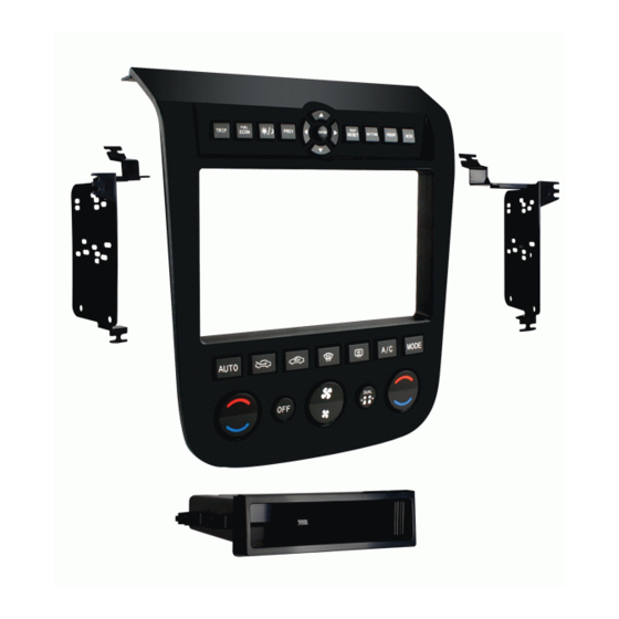
KIT COMPONENTS
• A) Radio Housing • B) Radio Housing Brackets • C) Pocket • D) (14) #8 x 3/8" Phillips screws
• E) (2) #8 x 1/2" Phillips screws • F) 7612 wire harness • G) Female 3.5mm Connector w/ Brown and Brown/White Wires
A
WIRING & ANTENNA CONNECTIONS (Sold Separately)
Wiring Harness: • 70-7550 1995-Up Nissan Harness
Antenna Adapter: • 40-NI10 Nissan Antenna Adapter
Panel Removal Tool • Phillips Screwdriver • Socket Wrench
APPLICATIONS
99-7612A, 99-7612B
B
E
• 70-7551 1995-Up Nissan Amp Integration Harness
TOOLS REQUIRED
METRA. THE WORLD'S BEST KITS.™
1-800-221-0932
© COPYRIGHT 2004-2011 METRA ELECTRONICS CORPORATION
C
F
metraonline.com
D
G
Advertisement

Related Manuals for Metra Electronics 99-7612A


Summary of Contents for Metra Electronics 99-7612A
- Page 1 Wiring Harness: • 70-7550 1995-Up Nissan Harness • 70-7551 1995-Up Nissan Amp Integration Harness Antenna Adapter: • 40-NI10 Nissan Antenna Adapter TOOLS REQUIRED Panel Removal Tool • Phillips Screwdriver • Socket Wrench METRA. THE WORLD’S BEST KITS.™ metraonline.com 1-800-221-0932 © COPYRIGHT 2004-2011 METRA ELECTRONICS CORPORATION...
- Page 2 99-7612 Table of Contents Dash Disassembly – Nissan Murano 2003-2007 Kit Assembly – ISO DIN head unit provision with pocket – DDIN head unit provision Caution Metra recommends disconnecting the negative battery terminal before beginning any installation. All accessories, switches, and especially air bag indicator lights must be plugged in before reconnecting the battery or cycling the ignition.
-
Page 3: Dash Disassembly
99-7612 Dash Disassembly 1. Unclip and remove the trim panel surrounding the display and including the a/c vents. (Figure A) 2. Remove (2) Phillips screws exposed behind vent/display trim panel. (Figure B) 3. Unclip and remove the lower trim panel around the bottom of the radio panel. - Page 4 99-7612 Dash Disassembly 4. Remove (1) Phillips screw per side of radio chassis exposed behind lower trim panel. (Figure D) 5. Remove radio/climate control assembly from the sub dash. 6. Remove (4) Phillips screws securing the radio chassis to the factory radio trim panel.
- Page 5 99-7612 Dash Disassembly 8. Remove the unified meter a/c amp from radio chassis assembly. (Figure G) 9. Remove (8) Phillips screws securing the switch panel to the radio trim panel. Unplug and keep the harness and trim panel for Kit Assembly. (Figure H) Continue to kit assembly (Figure G) (Figure H)
- Page 6 Kit Assembly 99-7612 ISO DIN head unit provision with pocket 1. Trim the shaded areas from the factory radio trim panel. (Figure A) Do not cut the locator and screw hole off as they will be necessary to mount the 99-7612 radio housing.
- Page 7 Kit Assembly 99-7612 ISO DIN head unit provision with pocket 5. Mount the Unified Amp Meter to the radio/bracket assembly using (2) supplied 3/8” Phillips screws. (Figure D) 6. Mount the whole radio/pocket/meter assembly to the radio trim panel using (4) supplied 3/8”...
- Page 8 Kit Assembly 99-7612 DDIN head unit provision 1. Trim the shaded areas from the factory radio trim panel. (Figure A) Do not cut the locator and screw hole off as they will be necessary to mount the 99-7612 radio housing. (See detail) 2.
- Page 9 Kit Assembly 99-7612 DDIN head unit provision 4. Mount the Unified Amp Meter to the radio/bracket assembly using (2) supplied 3/8” Phillips screws. (Figure D) 5. Mount the whole DDIN radio/meter assembly to the radio trim panel using (4) supplied 3/8” Phillips screws. (Figure E) 6.
- Page 10 99-7612 Wiring Instructions *Important: Before beginning any of the following, disconnect the negative battery terminal to prevent an accidental short circuit. 1. Plug the black 16-way connector into the 99-7612. 2. Plug the black 12-way connector into the 99-7612. 3. Plug the white 16-way connector into the factory harness. 4.
- Page 11 99-7612 SWC Button Reassignment/Remapping Let’s say you have the 99-7612 programmed to your vehicle and your radio and you want to change the button assignment for the steering wheel controls. For instance you would like Seek Up to be Mute. •...
- Page 12 99-7612 SWC Button Reassignment/Remapping For instance the next command to be mapped is the Volume Down command. Let’s say you want the Mode button on your steering wheel to be the Volume Down command. Hold down the Mode button till the LED lights up solid red, and then release it. Now your Mode button on the steering wheel is Volume Down.
- Page 13 Notes...
- Page 14 Notes...
- Page 15 Notes...
- Page 16 INSTALLATION INSTRUCTIONS FOR PART 99-7612 METRA. THE WORLD’S BEST KITS.™ metraonline.com 1-800-221-0932 © COPYRIGHT 2004-2011 METRA ELECTRONICS CORPORATION...
Need help?
Do you have a question about the 99-7612A and is the answer not in the manual?
Questions and answers