Table of Contents
Advertisement
Service
This manual is to be used by qualified appliance
technicians only. Maytag does not assume any
responsibility for property damage or personal
injury for improper service procedures done by
an unqualified person.
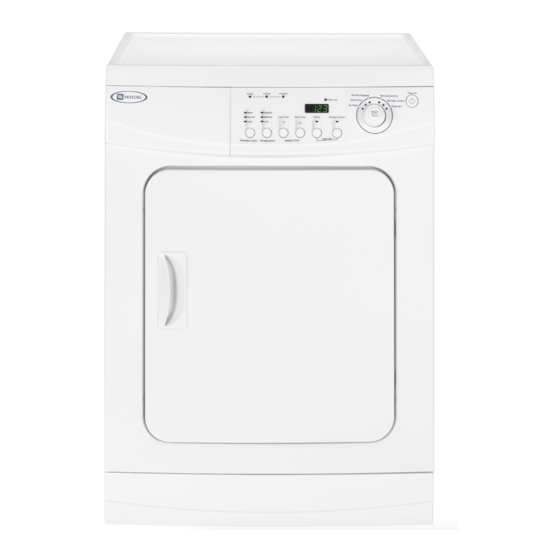
Compact Dryer
This Base Manual covers general information
Refer to individual Technical Sheet
for information on specific models
This manual includes, but is
not limited to the following:
MDE2400AY*
16023432
Revision 0
©2004 Maytag Services
Advertisement
Table of Contents
Troubleshooting

Related Manuals for Maytag MDE2400AY Series


Summary of Contents for Maytag MDE2400AY Series
- Page 1 Compact Dryer This Base Manual covers general information Refer to individual Technical Sheet for information on specific models This manual includes, but is not limited to the following: MDE2400AY* 16023432 Revision 0 ©2004 Maytag Services...
-
Page 2: Important Information
DANGER—Immediate hazards which WILL result in severe personal injury or death. WARNING WARNING—Hazards or unsafe practices which COULD result in severe personal injury or death. CAUTION CAUTION—Hazards or unsafe practices which COULD result in minor personal injury, product or property damage. 16023432 Rev. 0 ©2004 Maytag Services... -
Page 3: Table Of Contents
Drive Belt Removal ............ 20 Drum Removal ............21 Rear Seal Removal ........... 22 Motor/Blower Removal ..........22 Door Reversal ............24 Appendix A Installation Instructions ..........26 Appendix B Use And Care ............39 16023432 Rev. 0 ©2004 Maytag Services... -
Page 4: Important Safety Information
If they are and/or weather. 10. Do not tamper with dryer dried, wipe out the cylinder with a controls. damp cloth to remove particles of fiberglass. Save These Instructions 16023432 Rev. 0 ©2004 Maytag Services... -
Page 5: Electrical Service Information
A fuse in the neutral or ground circuit could result in an electrical shock. • DO NOT use an extension cord with this appliance. • DO NOT use an adapter plug with this appliance. • DO NOT pinch power cord. 16023432 Rev. 0 ©2004 Maytag Services... - Page 6 Important Safety Information 16023432 Rev. 0 ©2004 Maytag Services...
- Page 7 Important Safety Information 16023432 Rev. 0 ©2004 Maytag Services...
-
Page 8: General Information
Maytag’s strong warranty. This plan covers parts, labor, and travel charges. Call 1-800-925-2020 for information. Serial Label is located in the lower center of the door opening and back panel. 16023432 Rev. 0 ©2004 Maytag Services... -
Page 9: Model Nomenclature
Maytag Product Type Listing 120V-60hz Dryer Electric 240V-60hz Canada 240V-60hz 220-240 V / 50-60 Hz Marketing Code Feature Content This identifies which 2400 Feature Package version of production the unit is. Troubleshooting Guide Location. 16023432 Rev. 0 ©2004 Maytag Services... -
Page 10: Model Specifications
General Information 16023432 Rev. 0 ©2004 Maytag Services... -
Page 11: Troubleshooting Troubleshooting General Symptoms
• Popping or squealing sound. Check for a sticky • Hi-Limit trips easily or is open. or frayed belt. • Regulating thermostat trips easily or is open. • Membrane switch open. • Check Thermistor. 16023432 Rev. 0 ©2004 Maytag Services... -
Page 12: Component Electrical Testing
Heater Relay to Disconnect harness and Black wire Pin 2 on test White wire Pin 2 on Power Relay Heater Relay to Blue wire Pin 1 on Power Relay. Approx 26 ohms ± 5% Heater Power 16023432 Rev. 0 ©2004 Maytag Services... -
Page 13: Thermistor Check
Wire Pin 4. Less than 1ohm 6 5 4 3 2 1 Remove plug and test from Red wire Pin 1 to White wire Pin 6. Approx 60K ohms @ room temp. 6 5 4 3 2 1 16023432 Rev. 0 ©2004 Maytag Services... -
Page 14: Top Removal
1. Disconnect power supply to unit. 2. Remove 3 screws and Back Cover. FRONT SLIDE DRYER Thermostat Removal 1. Disconnect power supply to unit. 2. Remove Top Cover. 3. Remove screws and Heater Shield. 16023432 Rev. 0 ©2004 Maytag Services... -
Page 15: Heater Removal
View of the rear of the dryer cabinet with drum removed showing proper with drum removed showing proper Motor Harness Motor Harness wire harness routing and location of wire harness routing and location of retaining clips. retaining clips. 16023432 Rev. 0 ©2004 Maytag Services... -
Page 16: Console Removal
CAUTION: Do not cut wire tie without having a replacement on hand. Never reassemble dryer without wire ties in place. Note: There are 2 washers between the heater element housing and the heater cover. 16023432 Rev. 0 ©2004 Maytag Services... -
Page 17: Circuit Board Removal
1. Disconnect power supply to unit. 2. Remove the dryer top. 5. Unlatch the Console Blank. 3. Remove Console. 4. Remove 5 screws retaining the Circuit Board. 6. Remove screw on front face and right side of Console. 16023432 Rev. 0 ©2004 Maytag Services... -
Page 18: Front Panel/Door/Door Switch/Drum Glide Removal
5. Remove 1 upper screw attaching the Door Hinge to the Front Panel. Loosen but do not remove the 1 lower screw attaching the Door Hinge to the Front Panel. Repeat this step for the lower hinge. 16023432 Rev. 0 ©2004 Maytag Services... - Page 19 13. Disconnect the Door Switch wire harness. 9. Do not remove the center screw. 10.Remove 4 Front Panel retaining screws under Toe Panel . 11. Remove 3 Front panel retaining screws located on the top of the Front Panel. 16023432 Rev. 0 ©2004 Maytag Services...
-
Page 20: Drive Belt Removal
14.Service Front Drum Seal and Glides as needed. 6. Lift Inlet Panel from dryer. SEAL 7. Remove 3 screws retaining Back Cover to cabinet. 8. Release tension on belt by moving Tension Pulley toward the Drive Motor. GLIDE 16023432 Rev. 0 ©2004 Maytag Services... -
Page 21: Drum Removal
3. Remove Console. 4. Remove Front Panel. 5. Remove Rear Panel. 6. Remove Belt. 7. Remove 4 screws retaining Front Cross Brace. 10. Remove Retainer Ring on drum shaft. 8. Lift Front Cross Brace from dyer. 16023432 Rev. 0 ©2004 Maytag Services... -
Page 22: Rear Seal Removal
1. Disconnect power supply to unit. 2. Remove dryer Top Cover. 3. Remove Console. 4. Remove Front Panel. 5. Remove Rear Panel. 6. Remove Belt. 7. Remove Drum. 8. Release Tension spring from Motor Assembly. 16023432 Rev. 0 ©2004 Maytag Services... - Page 23 Remove Size 1/2” Size 7/8” Loosen 10.Remove Thermistor or Capacitor for servicing. 13. Remove 3 screws retaining Blower Housing to Motor face. 11. Remove 7 screws to Disassemble Motor/Blower Assembly Front Cover. 16023432 Rev. 0 ©2004 Maytag Services...
-
Page 24: Door Reversal
Repeat procedure for the lower hinge. 3. Lift the door and remove from dryer. 5. Remove door skin to expose inner door panel. 4. Remove 4 screws around perimeter of door. 16023432 Rev. 0 ©2004 Maytag Services... - Page 25 6. Remove the internal door and hinge components and 7. Reassemble the outer door skin to the Inner Door reassemble them to the opposite side of the Inner Panel. Door Panel. 8. Reassemble door to Dryer. 16023432 Rev. 0 ©2004 Maytag Services...
-
Page 26: Installation Instructions
A A A A A ppendix ppendix ppendix A A A A A ppendix ppendix 16023432 Rev. 0 ©2004 Maytag Services... - Page 27 16023432 Rev. 0 ©2004 Maytag Services...
- Page 28 16023432 Rev. 0 ©2004 Maytag Services...
- Page 29 16023432 Rev. 0 ©2004 Maytag Services...
- Page 30 16023432 Rev. 0 ©2004 Maytag Services...
- Page 31 16023432 Rev. 0 ©2004 Maytag Services...
- Page 32 16023432 Rev. 0 ©2004 Maytag Services...
- Page 33 16023432 Rev. 0 ©2004 Maytag Services...
- Page 34 16023432 Rev. 0 ©2004 Maytag Services...
- Page 35 16023432 Rev. 0 ©2004 Maytag Services...
- Page 36 2. Green or bare copper wire of power supply cord 3. 3/4 in. (1.9 cm) UL-listed strain relief 4. Center silver-colored terminal block screw 5. Neutral grounding wire (green/yellow) 6. Neutral wire (white or center wire) 16023432 Rev. 0 ©2004 Maytag Services...
- Page 37 16023432 Rev. 0 ©2004 Maytag Services...
- Page 38 2. Neutral grounding wire (green/yellow) 3. Center silver-colored terminal block screw 4. Neutral wire (white or center wire) 5. 3/4 in. (1.9 cm) UL-listed strain relief BEFORE OPERATING OR TESTING, be sure the machine is properly grounded. 16023432 Rev. 0 ©2004 Maytag Services...
-
Page 39: Appendix B Use And Care
A A A A A ppendix B ppendix B ppendix B ppendix B ppendix B 16023432 Rev. 0 ©2004 Maytag Services... - Page 40 16023432 Rev. 0 ©2004 Maytag Services...
- Page 41 16023432 Rev. 0 ©2004 Maytag Services...
- Page 42 16023432 Rev. 0 ©2004 Maytag Services...
- Page 43 16023432 Rev. 0 ©2004 Maytag Services...
- Page 44 16023432 Rev. 0 ©2004 Maytag Services...
- Page 45 16023432 Rev. 0 ©2004 Maytag Services...
- Page 46 16023432 Rev. 0 ©2004 Maytag Services...
- Page 47 16023432 Rev. 0 ©2004 Maytag Services...
- Page 48 16023432 Rev. 0 ©2004 Maytag Services...
- Page 49 16023432 Rev. 0 ©2004 Maytag Services...
- Page 50 16023432 Rev. 0 ©2004 Maytag Services...
- Page 51 16023432 Rev. 0 ©2004 Maytag Services...
Need help?
Do you have a question about the MDE2400AY Series and is the answer not in the manual?
Questions and answers