
Related Manuals for Kingspan Temperature differential controller

Summary of Contents for Kingspan Temperature differential controller
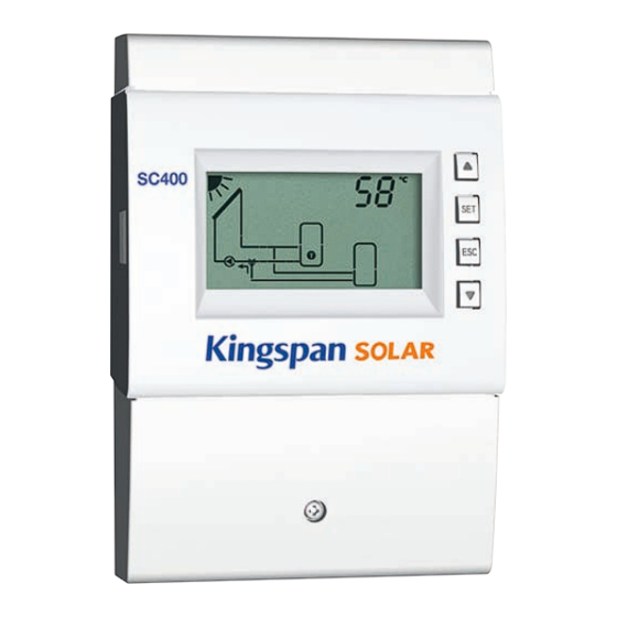
- Page 1 Temperature differential controller 5 inputs, 2 outputs Installation and operating instructions 742.892 | Z01 | 11.50 | Subject to change due to technical improvements!
-
Page 2: Table Of Contents
Content General safety instructions ........3 EC declaration of conformity.........3 Proper usage ............4 About this manual ..........4 Contents ..............4 Target audience ............4 Installation ............5 Opening / Closing the casing ........5 Mounting the casing ..........6 Establishing the electrical connections...... 7 Terminal pin assignments ........ -
Page 3: General Safety Instructions
14 Technical data ............50 14.1 Controller ............... 50 14.2 Cable specifications ..........51 Exclusion of liability ..........51 Legal guarantee ...........51 General safety instructions • This document is part of the product. • Use the device only after reading and understanding this document. • Keep this document in a safe place for the entire service life of the device. -
Page 4: Proper Usage
Proper usage The temperature differential controller, subsequently referred to as the controller, is an independently installed electronic temperature controller for on-surface installation. Integration into a pump assembly is possible when the technical specifications of the controller are adhered to. The maintenance-free controller is exclusively intended for controlling solar and heating systems. -
Page 5: Installation
Installation Note The following section describes only the installation of the controller. Follow the instruc- tions of each respective manufacturer when installing external components (collectors, pumps, storage tanks, valves etc.) Opening / Closing the casing 3.1.1 Removing the front panel ... -
Page 6: Mounting The Casing
Mounting the casing √ The mounting location must satisfy the prescribed conditions of use; more informa- tion on this is provided in Section 14, p. 50. √ The mounting surface is vertical and allows good access for installation. Danger Risk of death by electrocution! • Disconnect the controller from the power supply before opening the casing. -
Page 7: Establishing The Electrical Connections
Establishing the electrical connections Danger Risk of death by electrocution! Make sure that the following conditions are satisfied when performing the work described in this section: • All cables leading to the controller must be disconnected from the power supply and it must be ensured that they cannot be unintentionally reconnected during installa- tion. - Page 8 3.3.1 Position of the connection terminals Fig. 3: Terminal clamps in the lower part of the controller (terminal cover removed) Power connection terminal block 1x phase conductor (mains input) 2x output (TRIAC, for pumps or valves) R1, R2 not used 2x phase conductor (outputs, permanent voltage) const.
- Page 9 3.3.2 Preparing the cable openings The cables can be fed through openings in the rear wall of the casing or at the bottom of the casing. The openings are pre-punched and must be prepared as required before installation. Prepare the cable openings in the rear wall of the casing as follows: 1.
-
Page 10: Terminal Pin Assignments
Remove the plastic links as follows: 1. Insert a flat-blade screwdriver under the right plastic link between the casing and the spring clamp (Fig. 5). 2. Carefully push the flat-blade screwdriver to the left . Lever the spring clamp ... - Page 11 Display Legend Terminal layout 1 storage tank with heating return increase, 1 collector array T1: Collector array sensor T2: Lower storage tank sensor T3: Upper storage tank sensor T4: Sensor heating return increase R1: Solar circuit pump R1, N, PE (PWM R1, R2: Heating return switching valve R2, N, PE 1 storage tank with external heat exchanger, 1 collector array...
- Page 12 Display Legend Terminal layout 1 swimming pool, 1 collector array T1: Collector array sensor T2: Swimming pool sensor R2: Solar circuit pump R2, N, PE (PWM R2, 1 swimming pool with external heat exchanger, 1 collector array T1: Collector array sensor T2: Swimming pool sensor T3: External heat exchanger sensor R1: Solar circuit pump...
-
Page 13: Commissioning The Device For The First Time
Commissioning the device for the first time Danger Risk of death by electrocution! Be sure to perform all the measures listed in Section 3 before starting the first commissioning. Notes • After commissioning the controller for the first time, it is configured in such a man- ner that it can be used in most applications without changes. - Page 14 Commission the controller for the first time as follows: Setting the time 1. Apply power to the controller. – The time 12:00 is displayed. – 12 flashes (Fig. left) – The backlighting is red. 2. Press to set the hours. 3.
- Page 15 16. min, Value %, (pump 1) flash. Press to set the minimum speed of pump 1 in %. 17. Press SET. Make the settings for pump 2 (output R2) only if a system with 2 pumps was selected in step 7. Otherwise continue with step 20.
- Page 16 Characteristics of high-efficiency pumps Display Pump type Characteristic curve High-efficiency pump with a PWM profile 0% PWM: Pump off for a rising characteristic curve (Fig. 6) 100% PWM: Max. pump speed High-efficiency pump with a PWM profile 0% PWM: Max. pump speed for a falling characteristic curve (Fig.
-
Page 17: Construction
Construction Casing See sec- No. Element tion SC400 button (under 6.1, 7 Mode front panel) Operating buttons: , SET, ESC, Display Front panel Terminal cover 3.3.1 Terminal cover fastening – screw Section 3.3.1 describes the terminals under the terminal cover. - Page 18 5.2.2 System graphical symbols The following table describes the symbols used in the system graphics ( in Fig. 8). Symbol Description Symbol Description Pipework Pump, switched on Collector (array) Pump, switched off Maximum collector tempera- 3-way valve with flow direction ture reached Storage tank Domestic water outlet...
- Page 19 5.2.5 Operational and setting values The display of the operational and setting values ( in Fig. 8) consists of the following elements: Symbol for time control of functions. This symbol is displayed when: • a time restriction / control has been set, • the status of time restriction/control is displayed, • the time restriction blocks a temperature control (symbol flashes).
-
Page 20: Operation
Operation This section contains general information on operating the controller. Operating buttons The device is operated using the , , SET, ESC and buttons as follows: • Scrolls up through the menu • Increases the setting value by 1 step • Scrolls down through the menu ... -
Page 21: Off Mode
Off mode Functionality • All outputs are switched off (outputs/control outputs without power, relays open). • OFF and the software version are displayed alternately. See example in Fig. below: Software version St 1.3 • Backlighting is red. • Settings menu can be called up. • The Off mode is preset when the device is delivered. -
Page 22: Automatic Mode
Automatic mode Functionality Automatic is the normal mode of operation and the system is automatically controlled. The following actions are possible: • Display status (status display): Display the status of external components (tempera- tures, switching states, run times). • Display stored min./max. values (temperature sensors) or sum/difference values (op- erating hours of the pumps and valves). -
Page 23: Settings Menu
Operation √ The controller shows the status display. You can display the status of external components as follows: X - Press to display the status of other components ( , shown using system 1.1 as an example). You can display and reset the stored min./max./difference values as follows: 1. - Page 24 Time System Functions Set time No system – 0.1 Circulation – F01 1 storage tank, Back-up heating – F02 1 collector array – 1.1 1 storage tank with heating return increase, Solid fuel boiler – F03 1 collector array – 1.2 1 storage tank with external heat exchanger, Quick charge –...
- Page 25 Priority Factory setting Parameters SET for 5 seconds Storage tank 1 before Reset to factory Maximum temperature storage tank 1 – P01 storage tank 2 settings Storage tank 2 before Maximum temperature storage tank 2 – P02 storage tank 1 Maximum temperature swimming pool –...
-
Page 26: Calling Up The Settings Menu And Selecting A Menu Entry
Calling up the settings menu and selecting a menu entry √ Automatic or Off mode is selected. 1. Press and hold SET for two seconds. The settings menu is displayed, menu entry flashes. 2. Press to select a different menu entry. 3. -
Page 27: Setting The Priority
Setting the priority Functionality The priority determines the sequence in which the storage tanks are loaded (only for systems with more than 1 storage tank). If the higher priority storage tank (first-priority storage tank) cannot be loaded because the collector temperature is too low then the lower priority storage tank (second-priority storage tank) is loaded . -
Page 28: Functions
Functions Operation Displaying the functions The following information is visible when the functions are displayed: • Function number, e.g. F:01 (Fig. left) • Switching state: – on: Function is activated – off: Function is deactivated (Fig. left) Note If neither on nor off are displayed then the function can- not be used. -
Page 29: Characteristics
Setting the characteristics The functions have different numbers of characteristics. The characteristic values are always set via the same sequence of operating steps. You set the values of characteristics as follows: √ The function has been activated as described previously. 1. - Page 30 Switch-on temperature difference If a function contains a differential thermostat then the switch- on temperature difference can be set. The relevant sensor symbols flash. Switch-off temperature difference If a function contains a differential thermostat then the switch- off temperature difference can be set. The relevant sensor symbols flash.
-
Page 31: Function Descriptions
Starting time of a time window When setting the start time of a time window, the following is displayed to the left of the start time (see Fig. left): • • Number of time window 1 ... 3, whose start time is to be set (in this case: 1) • on End time of a time window... - Page 32 9.3.1 Circulation Switches a circulation pump on and off on a temperature and/or time controlled basis. Temperature control: If the temperature in the circulation return falls below the value, then the circulation pump is switched on until the temperature is reached. Time control: The circulation pump is switched on when the current time lies within one of 3 configurable time windows.
- Page 33 9.3.2 Back-up heating Performs temperature-dependent switching of an output for heating a storage tank using an oil or gas burner. The function can be time restricted. Temperature control: If the temperature in the storage tank falls below value, then the external heating is switched on until the tem- perature is reached.
- Page 34 Factory Display Characteristic min. max. setting Activation on, oFF Output (pump) free output R1/R2/R – Pump type (R1, R2 only) 1) 2) AC, HE Pump characteristic (HE only) AA, Ab, C (see page p. 16) – Speed control (R1, R2 only) on, oFF Minimum speed (AC only) 100%...
- Page 35 9.3.4 Quick charging Uses a higher loading temperature to load the the upper region of the storage tank more quickly in order to provide early prevention of back- up heating by the conventional heating system. To do this, the loading strategy of the first-priority storage tank is changed from differential loading to absolute temperature loading as soon as the temperature in the upper tank region drops below...
- Page 36 Type 1: Flow rate value at max. 99.9 l/min 0.0 l/min min. speed F (pump 1). max. When the Fig. at the left is dis- played (value flashes) then enter the value read from the flow rate display. Type 1: Flow rate value at min. 0.0 l/min 0.0 l/min max.
- Page 37 9.3.6 Thermostat Switches an output on and off, depending on the temperature range of any desired sensor. The function can be time restricted and is set for heating or cooling as follows: Heating: The T value is set lower than T When the sensor temperature drops below T , the output is switched on until the temperature exceeds T...
- Page 38 Factory Display Characteristic min. max. setting Activation on, oFF Output free output R1/R2/R – Pump type (R1, R2 only) 1) 2) AC, HE Pump characteristic (HE only) AA, Ab, C (see page p. 16) – Speed control (R1, R2 only) on, oFF Minimum speed (AC only) 100%...
- Page 39 9.3.8 Interval Periodically switches the solar circuit pump on and off in order to meas- ure the actual collector temperature. The delay between 2 switch-on operations and the switch-on duration can be set. Applications: • Collector types where the mechanical construction prevents the temperature from being measured at a suitable place • Unsuitable position of the temperature sensor on the collector The function can be time restricted to prevent unnecessary periodic...
- Page 40 9.3.10 Holiday - recooling Attempts to reduce, or even to avoid, the system standstill (stagnation) times at high temperatures. To do this, at night the storage tank – or the second-priority storage tank if 2 storage tanks are present – is dis- charged as far as possible to the set minimum temperature, if the stor- age tank temperature during the day was 10 K below the set maximum temperature.
- Page 41 9.3.12 Frost protection Attempts to prevent freezing of the collectors by pumping heat from the first-priority storage tank into the collectors: • The collector temperature is below +5 °C: Solar circuit pump is switched on. • The collector temperature is above +7 °C: Solar circuit pump is switched off.
- Page 42 9.3.14 Alarm output Activates the set output in the case of the following faults: • Sensor fault due to short-circuit or interruption • Clock loses the current time due to an extended power outage. • Volume flow fault: Er: 1 • The electronic overload switch or fuse has triggered: Er: 3 ...
-
Page 43: Parameters
Parameters Note the following when setting parameters: • Observe the operating data of the solar components used. • The individual parameters are only displayed and can be changed when this is per- mitted by the type of solar system that has been set. Special case: System 0.1 has no parameters, no P is displayed. - Page 44 Display Parameter min. max. Functionality Maximum collector + 20 K 180 °C 130 °C When the maximum collector temperature temperature is exceeded, no more loading occurs until the temperature drops to 3 K below the set value. Minimum collector 0 °C –...
- Page 45 Display Parameter min. max. Functionality Pump type R1 AC, HE Pump characteris- AA, Ab, C (see p. 16) – Caution tic (HE only) Danger of malfunctions in the Speed control controller or damage to the on, oFF (R1, R2 only) components.
-
Page 46: Deinstallation And Disposal
Deinstallation and disposal Danger Risk of death by electrocution! • Disconnect the device from the power supply before opening the casing. • All work on an open device must be performed by professional personnel. 1. To dismantle the controller, follow the installation instructions in the reverse order; see Section 3, p. -
Page 47: General Faults
13.1 General faults Display Possible cause Remedy Controller not functioning at all Display empty/ Controller power supply is interrupted. • Check the controller power dark cable. • Check the fuse for the power supply. Controller constantly displays 12:00 12 flashes Controller power supply was interrupted Set the time. -
Page 48: Error Messages
Solar circuit pump is operating + switch-on condition is fulfilled but no heat transport in the solar circuit (no heat transfer fluid circulation) Air is in the solar circuit. Check the solar circuit for air. The isolating valve is closed. Check the isolating valve. -
Page 49: Checking The Pt1000 Temperature Sensors
Output R1 is overloaded, the pump Check the electrical connected to output R1 flashes. data of the pump, Cause: The permissible values for R1 replace pump if specified on the type plate have been necessary. R1 is auto- permanently exceeded, the output has matically switched on been switched off. -
Page 50: Technical Data
Technical data 14.1 Controller Inputs/outputs Rated voltage (system voltage) 115 ... 230 V~, 50/60 Hz Own consumption ≤ 0.8 W, two Pt1000 temperature sensors connected Outputs R1, R2 Quantity Type TRIAC Switching current 1.1 (1.1) A each Voltage 115 ... 230 V~, 50/60 Hz Signal inputs/outputs Signal inputs 1 ... 5 Quantity Type of signal inputs 1 ... -
Page 51: Exclusion Of Liability
14.2 Cable specifications Mains cable Mains cable type H05 VV-... (NYM…) External diameter of mantle 6.5 mm to 10 mm Conductor cross-section single strand (solid) ≤ 2.5 mm fine strand (with core end sleeves) ≤ 1.5 mm Diameter of the internal strain 6.5 mm to 10 mm relief Signal cable Sensor cable length... - Page 52 742892 742.892 | 11.50...
Need help?
Do you have a question about the Temperature differential controller and is the answer not in the manual?
Questions and answers