Table of Contents
Advertisement
Quick Links
Advertisement
Table of Contents

Related Manuals for Gateway MG1


Summary of Contents for Gateway MG1
- Page 1 SERVICEGUIDE ®...
-
Page 2: Revision History
© 2008 Gateway, Inc. All rights reserved. Gateway, Gateway Country, the Gateway stylized logo, and the black-and-white spot design are trademarks or registered trademarks of Gateway, Inc. in the United States and other countries. All other brands and product names are trademarks or registered trademarks of their respective companies. -
Page 3: Table Of Contents
Contents Chapter 1: System specifications ......1 Preface ............2 Conventions . - Page 4 Contents Using the EZ Pad touchpad ....... . 30 Using the optional multimedia panel ......32 Using the optional webcam .
- Page 5 Replacing the modem jack/USB board ......136 Replacing the fan(s) ..........139 Chapter 4: Troubleshooting.
- Page 6 Contents Microsoft® Windows® Vista Environment Test ....176 Appendix C: Online support information ....179...
-
Page 7: Chapter 1: System Specifications
CHAPTER System specifications • Preface • Features • System block diagram • Hardware specifications and configurations • Notebook product tour... -
Page 8: Preface
CHAPTER 1: System specifications Preface Conventions The following conventions are used in this manual: Indicates a potential for personal injury. Caution Indicates a potential loss of data or damage to equipment. Important Indicates information that is important to know for the proper completion of a procedure, choice of an option, or completing a task. - Page 9 Display and graphics • 17" WUXGA/WSXGA TFT LCD display panel VGA Memory: VGA Controller: Dual independent display support 16.7 million colors MPEG-2/DVD hardware-assisted capability (acceleration) <Please verify> MPEG-2/DVD decoding (for selected models) <Please verify> WMV9 (VC-1) support (acceleration) <Please verify>...
- Page 10 I/O Ports and devices • • • Modem (RJ11) (optional) • Ethernet (RJ45) • IEEE1394 • eSATA • Headphone/SPDIF Audio Out • Microphone in • DC in jack for AC adapter ExpressCard™/54 slot Fingerprint reader (optional) 5-in-1 card reader (SD™, MMC, MS, MS PRO, xD) HDMI™...
-
Page 11: System Block Diagram
System block diagram... -
Page 12: Hardware Specifications And Configurations
Hardware specifications and configurations Item Specification CPU type Intel Merom Core Duo and Merom-Lite Core logic Intel GM45/GL40 + ICH9M/ICH9ME CPU package Socket-P, µFCPGA CPU core voltage <Please provide> Controllers Item Controller Core logic Intel GM45/GL40/PM45 + ICH9M/ICH9ME Intel Crestline-GM ■... -
Page 13: Bios
BIOS Item Specification BIOS vendor Phoenix BIOS Version 9C.XX ■ 94.XX ■ BIOS ROM type <Please provide> BIOS ROM size <Please provide> BIOS package <Please provide> Supported protocols <Please Verify> ACPI 1.0b/2.0/3.0 compliance ■ PCI 2.2 or later ■ System/HDD Password Security Control ■... -
Page 14: Hard Disk Drive
CHAPTER 1: System specifications Item Specification Supports memory size per 2 GB per SO-DIMM ■ socket 4 GB per SO-DIMM ■ Supports maximum 4 GB ■ memory size 8 GB ■ Supports SO-DIMM type DDR 2 Synchronous DRAM ■ DDR 3 Synchronous DRAM ■... -
Page 15: Keyboard
Item Specification Features <Please Verify> Unified Shader Architecture ■ Support Microsoft® DirectX® 10 Shader Model 4 ■ Geometry Instancing 2.0 ■ SGI OpenGL® 2.0 optimizations and support ■ Adaptive PCI Express interface ■ High efficiency integrated adaptable and programmable video processor (VP2) ■... -
Page 16: Memory Card Reader
CHAPTER 1: System specifications Memory card reader Item Specification Controller RTS5158 Cards supported Support 5-in-1 card reader (MMC, MS, MS-pro, SD, and xD) Compliancy <Please Verify> Complies to SDIO Host Interface Specification Rev 1.0 ■ Supports MMC, MMCplus, SD Memory, and SDIO cards ■... -
Page 17: Wired Lan
Item Specification Internal speaker/quantity 2 speakers (1.5 W per channel) Features 97 dB SNR DACs & 90 dB SNR ADCs ■ Enable VoIP function ■ Subwoofer support ■ Wired LAN Item Specification LAN chipset RealTek RTL8111C-GR Marvell 88E8057 Supports LAN protocol... -
Page 18: Modem
CHAPTER 1: System specifications Item Specification Protocol IEEE 802.11a ■ IEEE 802.11b ■ IEEE 802.11g ■ IEEE 802.11 Draft-N ■ Interface PCI bus (mini PCI socket for wireless module) Modem Item Specification Chipset Agere Delphi AM5 Form factor MDC 1.5 form factor Protocol ITU-T V.92, V.90 data mode with auto-fallback to, V.34, V.32terbo, and V.32bis. -
Page 19: Buttons/Indicators/Ports
Buttons/Indicators/Ports Item Specification Buttons Media control buttons and capacitive volume control on media panel ■ Power button ■ Windows Hotstart (select models only) ■ Wireless on/off switch ■ Indicators Wireless on/off ■ Caps Lock ■ Num Lock ■ Hard drive activity ■... -
Page 20: Fans
Item Specification Sensor CMOS 1/4 Power Built-in microphone On/Off Software Gateway Camera Assistant Fans CPU Temperature Fan Speed (rpm) Acoustic Level (dBA) <Please provide> <Please provide> <Please provide> Throttling 50%: % is controlled by operating system. Temperature point is 95°C OS shut down at 100°C;... -
Page 21: Power Supply
Power supply Item Specification Vendor Delta ■ Hipro ■ Input rating 90V AC to 264V AC, 47Hz to 63Hz Maximum input AC 1.5A (max) current Output rating 19V DC, 4.74A to 6.32A, 90W to 120W Power savings ACPI mode Power Management Mech. -
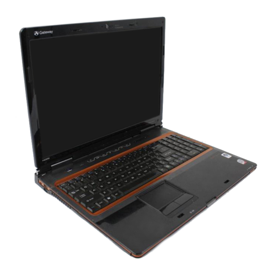
Page 22: Notebook Product Tour
CHAPTER 1: System specifications Notebook product tour Important Case color may vary from that shown in the pictures. Front Wireless network switch Power indicator LCD panel release latch Battery charge indicator Component Icon Description Power indicator LED on - Notebook is on. ■... -
Page 23: Right
Component Icon Description Ventilation fan Helps cool internal components. Warning: Do not work with the notebook resting on your lap. If the air vents are blocked, the notebook may become hot enough to harm your skin. Caution: Do not block or insert objects into these slots. If these slots are blocked, your notebook may overheat resulting in unexpected shutdown or permanent damage to the notebook. -
Page 24: Back
CHAPTER 1: System specifications Component Icon Description eSATA jack eSATA Connect an external SATA hard drive to this optional jack. (optional) Monitor port Plug an analog VGA monitor or projector into this port. Back Power connector Ventilation fan Modem jack Component Icon Description... -
Page 25: Bottom
Bottom Battery Battery latch Battery lock Customer Online Support: Tech Support Phone: Hours: care label Model: S/No: Memory bay Hard drive bay Component Icon Description Memory bay Memory modules are located in this bay. Battery latch Slide to release the battery. -
Page 26: Keyboard Area
CHAPTER 1: System specifications Keyboard area Multimedia panel Power button Speaker Speaker Keyboard Status indicators Touchpad Fingerprint reader Component Icon Description Keyboard Provides all the features of a full-sized, computer keyboard. Speakers Provide audio output when headphones or amplified speakers are not plugged in. -
Page 27: Lcd Panel
LCD panel Optional webcam Optional microphone Optional webcam status indicator Component Description Microphone (optional) Use to talk through when making Voice over Internet Protocol (VoIP) calls. Important: The optional microphone is only available when purchased with the optional webcam. -
Page 28: Using The Status Indicators
CHAPTER 1: System specifications Using the status indicators Important If none of the indicators are on, you may need to press F +F1 to toggle the status indicators on. Status indicators inform you when a drive is being used or when a button has been pressed that affects how the keyboard is used. -
Page 29: Using The Keyboard
Using the keyboard Your notebook features a full-size keyboard that functions the same as a desktop computer keyboard. Many of the keys have been assigned alternate functions, including shortcut keys for Windows and function keys for specific system operations. - Page 30 CHAPTER 1: System specifications Press and hold F To... then press this system key... Toggle the status indicators on or off. Turn the optional IEEE 802.11 wireless network radio on or off. Warning: Radio frequency wireless communication can interfere with equipment on commercial aircraft.
-
Page 31: Using The Optional Fingerprint Reader
Press and hold F To... then press this system key... Skip ahead one CD track or DVD chapter. Increase the brightness of the display. Decrease the brightness of the display. Increase volume. Decrease volume. Mute the sound. Press the key combination again to restore the sound. -
Page 32: Enrolling Your Fingerprints
CHAPTER 1: System specifications Features include: • Secure logon to Windows and fast user switching between user accounts • Password bank feature which records and replays passwords used in Windows and Web-based applications • A safe or folder for storing encrypted files that only a user with a matching fingerprint can access •... - Page 33 If you want to run the TouchStrip Tutorial, leave the Run interactive tutorial check box selected, then click Next. The TouchStrip Tutorial runs. After you have completed the tutorial, the Enrollment screen appears. -OR- If you do not want to run the TouchStrip Tutorial, click to uncheck the Run interactive tutorial check box, then click Next.
- Page 34 CHAPTER 1: System specifications Repeat step Step 6 two more times, then click Next. The Advanced Security screen appears. Type a password in the Backup password box, type the same password in the Retype password box, then click Next. Click Finish. Using the Fingerprint Control Center The Fingerprint Control Center lets the administrator of the notebook control how the fingerprint reader is used.
-
Page 35: Using The Fingerprint Reader Features
Click the yellow arrow in front of an option, then click the option or setting you want to change. Using the password bank The password bank stores registrations to your favorite secure Web sites so that you can access them without having to re-enter your username and password each time you want to log into the site. -
Page 36: Using The Ez Pad Touchpad
CHAPTER 1: System specifications Using the EZ Pad touchpad The EZ Pad™ consists of a touchpad, two buttons, and a scroll zone. Scroll zone Touchpad Left button Right button When you move your finger on the touchpad, the pointer (arrow) on the screen moves in the same direction. - Page 37 To... Do this... Move the Move your finger around on pointer on the the touchpad. If you run out of screen. space and need to move the pointer farther, lift your finger, move it to the middle of the touchpad, then continue moving your finger.
-
Page 38: Using The Optional Multimedia Panel
CHAPTER 1: System specifications Using the optional multimedia panel Capacitive volume control Windows Hotstart Mute sound Instant On Audio Skip ahead Instant On Video Skip back Play/Pause Stop Button Description Windows Hotstart—Turns on the notebook (if turned off) and opens Media Center (Windows Vista Home Premium or Windows Vista Ultimate) or Windows Media Player (Windows Vista Home Basic). -
Page 39: Using The Optional Webcam
Using the optional webcam You can use the optional webcam with many of the available Internet chat programs to add video and audio to your chat session. In addition, by using the software included with the webcam, you can take pictures or create video clips. - Page 40 CHAPTER 1: System specifications To use the webcam: Click (Start), All Programs, Camera Assistant Software, then click Camera Assistant Software. The Camera Assistant Toolbar opens. -OR- Right-click (Camera assistant software) on the taskbar, then click Show Toolbar. The Camera Assistant Toolbar opens. Button Icon Description...
- Page 41 Click (Start camera). The Camera Assistant opens. Click one of the following: Button Icon Description Snapshot Take a picture of what is currently in the preview screen. Video recording Create a video recording. Audio recording Create an audio recording.
- Page 42 CHAPTER 1: System specifications...
-
Page 43: Chapter 2: System Utilities
CHAPTER System utilities • BIOS Setup Utility • BIOS flash utility • Removing a password lock... -
Page 44: Bios Setup Utility
CHAPTER 2: System utilities BIOS Setup Utility The BIOS Setup Utility is a hardware configuration program built into the notebook’s BIOS (Basic Input/Output System). The notebook was shipped already properly configured and optimized. However, if the user encounters configuration problems, you may need to run Setup. -
Page 45: Bios Setup Utility Screens
BIOS Setup Utility screens Important The screens shown in this section are for informational purposes only. Screen information varies by model, features ordered, and location. Main screen The Main screen allows the user to set the system time and date as well as view a summary of your notebook hardware information. -
Page 46: Advanced Screen
Quiet Boot Determines if the Summary Option: Enabled or Disabled Screen is disabled or enabled. Enabled: The Gateway logo is displayed, and the Summary Screen is not displayed. Disabled: The Gateway logo is not displayed and the Summary Screen is displayed. -
Page 47: Security Screen
Security screen The Security screen contains parameters that help safeguard and protect your notebook from unauthorized use. Important Refer to “Removing a password lock” on page 49 if you need to know how to remove a Hard Drive or BIOS Password. - Page 48 CHAPTER 2: System utilities Parameter Description Option Fixed disk boot sector Write protects the boot sector Normal or Write Protect on the hard drive to protect against viruses. Password on Boot Defines whether a password Disabled or Enabled is required or not while the events defined in this group happened.
- Page 49 Press E . After setting the password, the value of Supervisor Password changes NTER to Set. Optional: you can enable the Password on Boot parameter. When you are done, press F10 to save your password and exit the BIOS Setup Utility or you can proceed to setting the User password.
- Page 50 CHAPTER 2: System utilities Changing a Password To change a password: ↑ ↓ Press to highlight Set Supervisor Password or Set User Password, then press E . The Set Supervisor Password or Set User Password box opens. NTER Type the current password in the Enter Current Password field, then press E NTER Important If you enter an incorrect current password, the screen displays the following.
- Page 51 Retype the password in the Confirm New Password field. Important If you do not enter the same new password and confirm new password, the screen displays the following. Press E , then re-enter the new password and NTER confirmation password.
- Page 52 CHAPTER 2: System utilities Boot This menu allows the user to decide the order of boot devices to load the operating system. Bootable devices include the onboard hard disk drive and the optical drive. Follow the instructions in Item Specific Help to change to boot order of the notebook devices. Exit The Exit screen contains options for leaving the BIOS Setup Utility and starting Windows.
- Page 53 Option Description Discard Changes Load previous values from CMOS for all SETUP items. Save Changes Save your changes to CMOS.
-
Page 54: Bios Flash Utility
CHAPTER 2: System utilities BIOS flash utility Use the BIOS flash memory update for the following conditions: • Install new versions of system programs. • Install a new BIOS with updated features or options. • Restore a BIOS when it becomes corrupted. Use the Phlash utility to update the system BIOS flash ROM. -
Page 55: Removing A Password Lock
If you need to solve System Disabled a BIOS password locked problem, you can <Reviewer: What is the Gateway procedure to remove a Supervisor password lock? If someone sends the unit in for repair, how does the repair tech remove the lock?>... - Page 56 CHAPTER 2: System utilities...
-
Page 57: Chapter 3: Replacing Notebook Components
CHAPTER Replacing notebook components • Preventing static electricity discharge • Preparing your work space • Tools required • Preparing the notebook • Adding or replacing memory modules • Replacing the main cooling assembly • Replacing the processor • Replacing the IEEE 802.11 wireless card •... -
Page 58: Preventing Static Electricity Discharge
CHAPTER 3: Replacing notebook components Preventing static electricity discharge Warning To avoid exposure to dangerous electrical voltages and moving parts, turn off your notebook, remove the battery, and unplug the power cord, modem cable, and network cable before opening the case. Warning To prevent risk of electric shock, do not insert any object into the vent holes of the notebook. -
Page 59: Preparing Your Work Space
Preparing your work space Before performing maintenance on the notebook, make sure that your work space and the notebook are correctly prepared. • Wear a grounding (ESD) wrist strap, and use a grounded or dissipative work mat. • Use a stable and strong table, and make sure that the table top is large enough to hold each component as you remove it. -
Page 60: Tools Required
CHAPTER 3: Replacing notebook components Tools required To disassemble the notebook, you need the following tools: • Wrist grounding strap and conductive mat for preventing electrostatic discharge • Flat screwdriver • Phillips screwdriver • Scribe or non-marring tool • Tweezers... -
Page 61: Preparing The Notebook
Preparing the notebook To prepare the notebook for maintenance: Make sure that the disc drive is empty. Turn off the notebook. Close the LCD panel. Disconnect the AC adapter, modem cable, and network cable. Disconnect all peripheral devices connected to the notebook and remove any Express Cards and memory cards. -
Page 62: Adding Or Replacing Memory Modules
CHAPTER 3: Replacing notebook components Adding or replacing memory modules Important Use only memory modules designed for this Gateway notebook. Tools you need to complete this task: Phillips #0 screwdriver Memory To add or replace memory modules: Complete the steps in “Preparing the notebook”... - Page 63 Use the thumb notch to lift the memory bay cover, then remove it. Be careful not to break off the tabs located on the end of the cover opposite the thumb notch. Thumb notch If you are removing a module, gently press outward on the clip at each end of the memory module until the module tilts upward.
-
Page 64: Replacing The Main Cooling Assembly
CHAPTER 3: Replacing notebook components Replacing the main cooling assembly Tools you need to complete this task: Phillips #0 screwdriver Screws removed during this task: 4 black M2×5 (main cooling assembly) (Optional) Additional materials you need to complete this task: •... - Page 65 Use the thumb notch to lift the cooling assembly bay cover, then remove it. Be careful not to break off the tabs located on the end of the cover opposite the thumb notch. Thumb notch Loosen or remove the screws that secure the main cooling assembly to the system board.
- Page 66 CHAPTER 3: Replacing notebook components Remove any thermal grease residue from the processor using a soft cloth and isopropyl alcohol. Place new thermal grease on the processor. Use only enough to cover the CPU die. Make sure a thermal pad is placed between the main cooling assembly and other components as shown.
-
Page 67: Replacing The Processor
Replacing the processor Tools you need to complete this task: Phillips #0 screwdriver Flat-blade driver Additional materials you need to complete this task: • X-23-7762 thermal grease Screws removed during this task: 4 black M2×5 (main cooling assembly) (Optional) - Page 68 CHAPTER 3: Replacing notebook components Remove the old processor from the system board. Install the new processor onto the system board making sure that Pin 1 on the processor (indicated by the silk-screened arrow on the corner of the processor) aligns with Pin 1 on the processor socket (indicated by the absence of a pin hole in the processor socket), then use a flat-blade screwdriver to turn the processor lock screw 1/4-turn clockwise.
-
Page 69: Replacing The Ieee 802.11 Wireless Card
Replacing the IEEE 802.11 wireless card Tools you need to complete this task: Phillips #0 screwdriver Screws removed during this task: 2 black M2×3 (IEEE 802.11 wireless card) Wireless To replace the IEEE 802.11 wireless card: Complete the steps in “Preparing the notebook”... - Page 70 CHAPTER 3: Replacing notebook components Use the thumb notch to lift the wireless bay cover, then remove it. Be careful not to break off the tabs located on the end of the cover opposite the thumb notch. Thumb notch Unplug the antenna cables. Note which color cable is connected to each of the connectors.
- Page 71 Remove the wireless card screws. Screw Screw Pull the card out of the slot. Move the antenna cables out of the way. Hold the new card at a 30-degree angle and slide it into the empty slot. This card is keyed so it can only be inserted in one direction.
-
Page 72: Replacing The Cmos Battery
CHAPTER 3: Replacing notebook components Replacing the CMOS battery Important Use only CMOS batteries designed for this Gateway notebook. Tools you need to complete this task: Flat-blade driver - OR - Scribe or non-marring tool Phillips #0 screwdriver Screws removed during this task: 2 black M2×3 (IEEE... - Page 73 Identify the type of battery used on the notebook. Some batteries are silver disks and fit within a special connector on the system board. Other batteries are encased within a special black sleeve and have a wire connector that connects to the system board.
- Page 74 CHAPTER 3: Replacing notebook components • Lift the old battery off of the system board. Important The battery is held in place by double-sided tape. • Connect the new battery to the system board, then place the battery on the system board.
-
Page 75: Replacing The Hard Drive
Replacing the hard drive Tools you need to complete this task: Phillips #0 screwdriver Screws removed during this task: 4 chrome M3×3 (Hard drive bracket) Hard drive bay To replace the hard drive: Complete the steps in “Preparing the notebook” on page... - Page 76 CHAPTER 3: Replacing notebook components Loosen the hard drive bay cover screws (these screws cannot be removed). Screw Screw Screw Screw Use the thumb notch to lift the hard drive bay cover, then remove it. Be careful not to break off the tabs located on the end of the cover opposite the thumb notch. Thumb notch...
- Page 77 Using the plastic tab, slide the hard drive you are replacing, then remove it. If your new hard drive already includes the hard drive bracket, go to step Step -OR- If you need to move the hard drive bracket from your old hard drive to your new...
- Page 78 CHAPTER 3: Replacing notebook components Remove the bracket from the old drive. Insert the new drive label side up onto the bracket so the screw holes line up. Replace the screws that secure the bracket to the drive. Slide the new hard drive kit into your notebook. Replace the cover, then tighten the screws.
-
Page 79: Replacing The Dvd Drive
Replacing the DVD drive Tools you need to complete this task: Flat-blade driver - OR - Scribe or non-marring tool Phillips #0 screwdriver Screws removed during this task: 1 black M2.5×5 (DVD drive) drive To replace the DVD drive: Complete the steps in “Preparing the notebook”... - Page 80 CHAPTER 3: Replacing notebook components Remove the rubber insert from the bottom of the notebook. Rubber insert Remove the screw that secures the DVD drive to your notebook. Screw...
- Page 81 Carefully slide the drive out of the drive bay. Use a small screwdriver or other pointed tool to push on the DVD bracket and slide the drive out of the bay. Slide the new DVD drive into the drive bay. Make sure that the drive fits securely in the bay.
-
Page 82: Replacing The Keyboard Cover
CHAPTER 3: Replacing notebook components Replacing the keyboard cover Tools you need to complete this task: Flat-blade driver - OR - Scribe or non-marring tool Phillips #0 screwdriver Screws removed during this task: 2 black M2.5×3 (Keyboard cover) To replace the keyboard cover: Complete the steps in “Preparing the notebook”... - Page 83 Pull the cover off the notebook by lifting the back corners of the cover. Be careful to not damage the LCD panel. Caution The cover is connected to the notebook by one or more cables. Do not pull on the cables.
- Page 84 CHAPTER 3: Replacing notebook components Make sure the black keyboard cover connector clip is fully moved toward the back of the notebook, insert the cable into the connector, then slide the black clip forward to lock the connector in place. Important The cable is correctly oriented if it is not twisted.
-
Page 85: Replacing The Keyboard
Replacing the keyboard Tools you need to complete this task: Flat-blade driver - OR - Scribe or non-marring tool Phillips #0 screwdriver Screws removed during this task: 4 black M2.5×3 2 black M2.5×3 1 long black (Keyboard) (Keyboard) (Keyboard cover) - Page 86 CHAPTER 3: Replacing notebook components Lift the back edge of the keyboard slightly, then slowly slide it toward the LCD panel to release the keyboard retaining tabs located on the front edge of the keyboard. Slide the keyboard connector clip to the back of the notebook or lift the connector clip off of the cable, then slide the cable out of the clip.
- Page 87 Replace the keyboard cover by following the steps in “Replacing the keyboard cover” on page...
-
Page 88: Replacing The Inverter
CHAPTER 3: Replacing notebook components Replacing the inverter Tools you need to complete this task: Flat-blade driver - OR - Scribe or non-marring tool Phillips #0 screwdriver Screws removed during this task: 6 black M2.5×8 (LCD 2 black M2.5×5 (inverter) 2 black M2.5×3 front panel) (Keyboard cover) - Page 89 Remove the screws from the front of the LCD panel assembly. Screw Screw Screw Screw Screw Screw Carefully separate the front and back of the LCD panel assembly. Remove the screws connecting the inverter to the LCD panel lid.
- Page 90 CHAPTER 3: Replacing notebook components Disconnect the connectors from the old inverter and connect them to the new inverter. Align the new inverter with the screw holes, then replace the screws removed in Step Press the LCD panel front and back together. Press the two halves together in several places until they click in place.
-
Page 91: Replacing The Webcam
Replacing the webcam Tools you need to complete this task: Flat-blade driver - OR - Scribe or non-marring tool Phillips #0 screwdriver Screws removed during this task: 6 black M2.5×8 (LCD 2 black M2.5×3 2 black M2×3 (Webcam) front panel) - Page 92 CHAPTER 3: Replacing notebook components Remove the screws from the front of the LCD panel assembly. Screw Screw Screw Screw Screw Screw Carefully separate the front and back of the LCD panel assembly. Disconnect the webcam cable from the webcam. Remove the screws that connect the webcam bracket to the LCD panel assembly.
- Page 93 Remove the old webcam. Install the new webcam. Replace the screws that were removed in Step Reconnect the webcam cable. Press the LCD panel front and back together. Press the two halves together in several places until they click in place. You should find no loose spots or spots where the two halves do not meet.
-
Page 94: Replacing The Lid Latches
CHAPTER 3: Replacing notebook components Replacing the lid latches Tools you need to complete this task: Flat-blade driver - OR - Scribe or non-marring tool Phillips #0 screwdriver Screws removed during this task: 6 black M2.5×8 (LCD 2 black M2.5×3 2 black M2.5×5 (Lid front panel) (Keyboard cover) - Page 95 Remove the screws from the front of the LCD panel assembly. Screw Screw Screw Screw Screw Screw Carefully separate the front and back of the LCD panel assembly. Remove the screws that connect the lid latches to the LCD panel assembly.
- Page 96 CHAPTER 3: Replacing notebook components Replace the LCD panel assembly screws removed in Step Replace the rubber inserts removed in Step Replace the keyboard cover by following the steps in “Replacing the keyboard cover” on page...
-
Page 97: Replacing The Lcd Assembly
Replacing the LCD assembly Tools you need to complete this task: Flat-blade driver - OR - Scribe or non-marring tool Phillips #0 screwdriver Screws removed during this task: 4 black M2.5×3 2 black M2.5×3 1 long black (Keyboard) (Keyboard) (Keyboard cover) 2 black M2.5×8 (Hinge... - Page 98 Taking care to note the cables’ routing and positions as they are installed from Gateway, pull the antenna cables out from under the system board, then slide the antenna cables and LCD cables out from under the retaining clips. Remove any tape that may be securing the cables.
- Page 99 Place the new LCD panel assembly onto the notebook, then replace the hinge screws removed in Step Slide the antenna cables through the retaining clips, under the system board, then into the wireless bay. Lay the LCD cable along the flat area under the keyboard, then plug it into the notebook.
-
Page 100: Replacing The Lcd Panel
CHAPTER 3: Replacing notebook components Replacing the LCD panel Tools you need to complete this task: Flat-blade driver - OR - Scribe or non-marring tool Phillips #0 screwdriver Screws removed during this task: 4 black M2.5×3 2 black M2.5×3 1 long black (Keyboard) (Keyboard) (Keyboard cover) 6 black M2.5×8 (LCD... - Page 101 Remove the rubber inserts from the front of the LCD panel assembly. Insert Insert Insert Insert Insert Insert Remove the screws from the front of the LCD panel assembly. Screw Screw Screw Screw Screw Screw Carefully separate the front and back of the LCD panel assembly.
- Page 102 CHAPTER 3: Replacing notebook components Remove the screws that secure the LCD panel to the LCD panel lid. Screw Screw Screw Screw Remove the inverter by following the steps in “Replacing the inverter” on page Disconnect the web cam by following the steps in “Replacing the webcam”...
- Page 103 Replace the keyboard by following the steps in “Replacing the keyboard” on page Replace the keyboard cover by following the steps in “Replacing the keyboard cover” on page Turn the notebook over so the bottom is facing up. Reconnect the antenna wires to the wireless card by following the steps in “Replacing the IEEE 802.11 wireless card”...
-
Page 104: Replacing The Lcd Panel Hinges
CHAPTER 3: Replacing notebook components Replacing the LCD panel hinges Tools you need to complete this task: Flat-blade driver - OR - Scribe or non-marring tool Phillips #0 screwdriver Screws removed during this task: 4 black M2.5×3 2 black M2.5×3 1 long black (Keyboard) (Keyboard) (Keyboard cover) - Page 105 Remove the rubber inserts from the front of the LCD panel assembly. Insert Insert Insert Insert Insert Insert Remove the screws from the front of the LCD panel assembly. Screw Screw Screw Screw Screw Screw Carefully separate the front and back of the LCD panel assembly.
- Page 106 CHAPTER 3: Replacing notebook components Remove the screws that secure the LCD panel to the LCD panel lid. Screw Screw Screw Screw Carefully raise each of the bottom corners of the LCD panel and replace the old hinges with new hinges. Replace the screws that were removed in Step Make sure that the magnet has remained in the magnet bracket.
- Page 107 Replace the wireless bay cover by following the steps in “Replacing the IEEE 802.11 wireless card” on page...
-
Page 108: Replacing The Lcd Assembly Lid
CHAPTER 3: Replacing notebook components Replacing the LCD assembly lid Tools you need to complete this task: Flat-blade driver - OR - Scribe or non-marring tool Phillips #0 screwdriver Screws removed during this task: 4 black M2.5×3 2 black M2.5×3 1 long black (Keyboard) (Keyboard) (Keyboard cover) - Page 109 If the notebook has wireless networking built in, unplug the wireless antennas by following the steps in “Replacing the IEEE 802.11 wireless card” on page Remove the keyboard cover by following the steps in “Replacing the keyboard cover” on page Remove the keyboard by following the steps in “Replacing the keyboard”...
-
Page 110: Replacing The Palm Rest
CHAPTER 3: Replacing notebook components Replacing the palm rest Tools you need to complete this task: Flat-blade driver - OR - Scribe or non-marring tool Phillips #0 screwdriver Screws removed during this task: 4 black M2.5×3 2 black M2.5×3 1 long black (Keyboard) (Keyboard) (Keyboard cover) 8 black M2.5×8 (Palm... - Page 111 If the notebook has wireless networking built in, unplug the wireless antennas by following the steps in “Replacing the IEEE 802.11 wireless card” on page Remove the hard drive by following the steps in “Replacing the hard drive” on...
- Page 112 CHAPTER 3: Replacing notebook components Remove the screws from the top of the palm rest. Note the location of the screw types and sizes. Long screw Screw Screw Long screw Screw Long screw Long screw Optional short screw Long screw Long screw Lift the palm rest assembly up from the notebook.
- Page 113 Replace the LCD assembly by following the steps in “Replacing the LCD assembly” on page Replace the keyboard by following the steps in “Replacing the keyboard” on page Replace the keyboard cover by following the steps in “Replacing the keyboard cover”...
-
Page 114: Replacing The Touchpad Board
CHAPTER 3: Replacing notebook components Replacing the touchpad board Tools you need to complete this task: Flat-blade driver - OR - Scribe or non-marring tool Phillips #0 screwdriver Screws removed during this task: 4 black M2.5×3 2 black M2.5×3 1 long black (Keyboard) (Keyboard) (Keyboard cover) 8 black M2.5×8 (Palm... - Page 115 If the notebook has wireless networking built in, unplug the wireless antennas by following the steps in “Replacing the IEEE 802.11 wireless card” on page Remove the hard drive by following the steps in “Replacing the hard drive” on...
- Page 116 CHAPTER 3: Replacing notebook components Swing the brown touchpad connector clip upward, then lift the cable out of the connector. Be careful not to touch or damage any other components. Touchpad connector Fingerprint reader connector Touchpad button board connector Remove the touchpad board bracket from the notebook. Remove the touchpad board from the notebook.
- Page 117 Make sure the brown touchpad connector clip is up, insert the cable into the connector, then swing the clip down to lock the connector in place. Important The touchpad cable is correctly oriented if the blue side is showing.
-
Page 118: Replacing The Touchpad Button Board
CHAPTER 3: Replacing notebook components Replacing the touchpad button board Tools you need to complete this task: Flat-blade driver - OR - Scribe or non-marring tool Phillips #0 screwdriver Screws removed during this task: 4 black M2.5×3 2 black M2.5×3 1 long black (Keyboard) (Keyboard) (Keyboard cover) - Page 119 If the notebook has wireless networking built in, unplug the wireless antennas by following the steps in “Replacing the IEEE 802.11 wireless card” on page Remove the hard drive by following the steps in “Replacing the hard drive” on...
- Page 120 CHAPTER 3: Replacing notebook components Remove the touchpad button board from the notebook. Place the new touchpad button board into the notebook in the same orientation as the old board. Replace the screws removed in Step Replace the touchpad board by following the steps in “Replacing the touchpad board”...
-
Page 121: Replacing The Fingerprint Reader
Replacing the fingerprint reader Tools you need to complete this task: Flat-blade driver - OR - Scribe or non-marring tool Phillips #0 screwdriver Screws removed during this task: 4 black M2.5×3 2 black M2.5×3 1 long black (Keyboard) (Keyboard) (Keyboard cover) 8 black M2.5×8 (Palm... - Page 122 CHAPTER 3: Replacing notebook components If the notebook has wireless networking built in, unplug the wireless antennas by following the steps in “Replacing the IEEE 802.11 wireless card” on page Remove the hard drive by following the steps in “Replacing the hard drive” on page Remove the keyboard cover by following the steps in “Replacing the keyboard...
- Page 123 Replace the wireless bay cover by following the steps in “Replacing the IEEE 802.11 wireless card” on page...
-
Page 124: Replacing The Bluetooth Module
CHAPTER 3: Replacing notebook components Replacing the Bluetooth module Tools you need to complete this task: Flat-blade driver - OR - Scribe or non-marring tool Phillips #0 screwdriver Screws removed during this task: 4 black M2.5×3 2 black M2.5×3 1 long black (Keyboard) (Keyboard) (Keyboard cover) 8 black M2.5×8 (Palm... - Page 125 If the notebook has wireless networking built in, unplug the wireless antennas by following the steps in “Replacing the IEEE 802.11 wireless card” on page Remove the hard drive by following the steps in “Replacing the hard drive” on...
- Page 126 CHAPTER 3: Replacing notebook components Replace the keyboard by following the steps in “Replacing the keyboard” on page Replace the keyboard cover by following the steps in “Replacing the keyboard cover” on page Replace the hard drive by following the steps in “Replacing the hard drive”...
-
Page 127: Replacing The Modem
Replacing the modem Tools you need to complete this task: Flat-blade driver - OR - Scribe or non-marring tool Phillips #0 screwdriver Screws removed during this task: 4 black M2.5×3 2 black M2.5×3 1 long black (Keyboard) (Keyboard) (Keyboard cover) 8 black M2.5×8 (Palm... - Page 128 CHAPTER 3: Replacing notebook components If the notebook has wireless networking built in, unplug the wireless antennas by following the steps in “Replacing the IEEE 802.11 wireless card” on page Remove the hard drive by following the instructions in “Replacing the hard drive” on page Remove the keyboard cover by following the steps in “Replacing the keyboard...
- Page 129 Lift the modem off of the system board. Turn the modem over, then unplug the modem cable from the old modem and plug the cable into the new modem. Install the new modem on the system board. Replace the screws remove in...
- Page 130 CHAPTER 3: Replacing notebook components Replace the LCD assembly by following the steps in “Replacing the LCD assembly” on page Replace the keyboard by following the steps in “Replacing the keyboard” on page Replace the keyboard cover by following the steps in “Replacing the keyboard cover”...
-
Page 131: Replacing The Speakers
Replacing the speakers Tools you need to complete this task: Flat-blade driver - OR - Scribe or non-marring tool Phillips #0 screwdriver Screws removed during this task: 4 black M2.5×3 2 black M2.5×3 1 long black (Keyboard) (Keyboard) (Keyboard cover) 8 black M2.5×8 (Palm... - Page 132 CHAPTER 3: Replacing notebook components If the notebook has wireless networking built in, unplug the wireless antennas by following the steps in “Replacing the IEEE 802.11 wireless card” on page Remove the hard drive by following the instructions in “Replacing the hard drive” on page Remove the keyboard cover by following the steps in “Replacing the keyboard...
- Page 133 Replace the keyboard by following the steps in “Replacing the keyboard” on page Replace the keyboard cover by following the steps in “Replacing the keyboard cover” on page Replace the hard drive by following the instructions in “Replacing the hard drive”...
-
Page 134: Replacing The System Board And Vga Cooling Assembly
CHAPTER 3: Replacing notebook components Replacing the system board and VGA cooling assembly Tools you need to complete this task: Flat-blade driver - OR - Scribe or non-marring tool Phillips #0 screwdriver Additional materials you need to complete this task: •... - Page 135 Screws removed during this task (cont): 2 black M2×3 (Bluetooth 2 black M2×3 (Modem) 1 black M2.5×3 (Right module) speaker) 2 black M2.5×5 (VGA cooling assembly) 2 black M2.5×5 (EMI 4-6 black M2.5×5 (Optional) shield) (Optional) (System board) To replace the system board and VGA cooling assembly: Complete the steps in “Preparing the notebook”...
- Page 136 CHAPTER 3: Replacing notebook components Unplug the Bluetooth module from the system board (one connector). Unplug the speakers from the system board (one connector). Remove the modem by following the instructions in “Replacing the modem” on page 121. Important You can keep the modem connected to the modem cable. Remove the modem cable from the system board retaining clips.
- Page 137 Remove the screw holding the right speaker to the notebook, then remove the speaker. Unplug the fan(s) from the system board. Remove the optional EMI shield screws. Screw Screw...
- Page 138 CHAPTER 3: Replacing notebook components Remove the system board screws. Screw Screw Screw Screw Screw Screw -OR- Screw Screw Screw Screw...
- Page 139 Carefully remove the system board. Turn the old system board over, then remove the optional second cooling assembly from the system board. Screw Screw Screw Screw Remove any thermal grease residue from the second cooling assembly using a soft cloth and isopropyl alcohol.
-
Page 140: Replace The Keyboard By Following The Steps In Page
CHAPTER 3: Replacing notebook components • The small black switch on the system board fits within the slot on the wireless network on/off switch. If it does not, the wireless network may not work. Slot • The connector between this board and the modem jack/USB board is fully connected. -
Page 141: If The Notebook Has Wireless Networking Built In, Reconnect The Wireless Antennas
If the notebook has wireless networking built in, reconnect the wireless antennas by following the steps in “Replacing the IEEE 802.11 wireless card” on page Replace the cooling assembly by following the instructions in “Replacing the main cooling assembly” on page... -
Page 142: Replacing The Modem Jack/Usb Board
CHAPTER 3: Replacing notebook components Replacing the modem jack/USB board Tools you need to complete this task: Flat-blade driver - OR - Scribe or non-marring tool Phillips #0 screwdriver Additional materials you need to complete this task: • X-23-7762 thermal grease Screws removed during this task: 4 black M2×5 (main 1 black M2.5×5 (DVD... -
Page 143: Replacing The Keyboard" On
Screws removed during this task (cont.): 2 black M2×3 (Modem) 2 black M2.5×3 (Left 1 black M2.5×3 (Right speaker) speaker) 7 black M2.5×5 (System 1 black M2.5×5 (Modem board) jack/USB board) To replace the modem jack/USB board: Complete the steps in “Preparing the notebook”... - Page 144 CHAPTER 3: Replacing notebook components Remove the modem jack/USB board screw. Screw Lift the old modem jack/USB board from the notebook. Set the new modem jack/USB board module into the notebook, then replace the screw removed in Step Replace the system board by following the steps in “Replacing the system board and VGA cooling assembly”...
-
Page 145: Replacing The Fan(S)
Replacing the fan(s) Tools you need to complete this task: Flat-blade driver - OR - Scribe or non-marring tool Phillips #0 screwdriver Additional materials you need to complete this task: • X-23-7762 thermal grease Screws removed during this task: 4 black M2×5 (main... - Page 146 CHAPTER 3: Replacing notebook components Screws removed during this task: 7 black M2.5×5 (System 2 black M2×3 (Modem) 1 black M2.5×3 (Right board) speaker) 2 black M2.5×5 (Fans) To replace the fan(s): Complete the steps in “Preparing the notebook” on page Remove the cooling assembly by following the instructions in “Replacing the main cooling assembly”...
- Page 147 Remove the fan screws. Screw Screw Lift the old fan from the notebook. Set the new fan into the notebook, then replace the screws removed in Step Replace the system board by following the steps in “Replacing the system board and VGA cooling assembly”...
- Page 148 CHAPTER 3: Replacing notebook components If the notebook has wireless networking built in, reconnect the wireless antennas by following the steps in “Replacing the IEEE 802.11 wireless card” on page Replace the cooling assembly by following the instructions in “Replacing the main cooling assembly”...
-
Page 149: Chapter 4: Troubleshooting
CHAPTER Troubleshooting • Diagnosing problems • System test procedures • Power-On Self-Test (POST) error message • Index of error messages • Phoenix BIOS beep codes • Symptom-to-FRU error messages • Intermittent problems • Undetermined problems... -
Page 150: Diagnosing Problems
CHAPTER 4: Troubleshooting Diagnosing problems Use the following procedure as a guide for diagnosing notebook problems. Important The diagnostic tests are intended to test only Acer products. Non-Acer products, prototype cards, or modified options can give false errors and invalid system responses. Obtain the failing symptoms in as much detail as possible. -
Page 151: Testing The Keyboard Or Auxiliary Input Device
Replace the system board. Testing the keyboard or auxiliary input device If the internal keyboard does not work or an unexpected character appears, make sure that the flexible cable extending from the keyboard is correctly seated in the connector on the system board. - Page 152 CHAPTER 4: Troubleshooting • “Check the power adapter” on page 146 • “Check the battery pack” on page 146 Check the power adapter Unplug the power adapter cable from the notebook and measure the output voltage at the power adapter cable plug. See the following figure. Pin 1: +19 to +20.5V Pin 2: 0V, Ground •...
-
Page 153: Testing The Touchpad
Testing the touchpad If the touchpad doesn’t work, do the following actions one at a time to correct the problem. To test the touchpad: Reconnect the touchpad cables. Replace the touchpad. Replace the system board. Important Do not replace a non-defective FRU. -
Page 154: Index Of Error Messages
CHAPTER 4: Troubleshooting Index of error messages Error codes Error Codes Error Messages Equipment Configuration Error Causes: 1. CPU BIOS Update Code Mismatch 2. IDE Primary Channel Master Drive Error (The causes are shown before “Equipment Configuration Error”) Memory Error at xxxx:xxxx:xxxxh (R:xxxxh, W:xxxxh) Real Time Clock Error CMOS Battery Bad CMOS Checksum Error... - Page 155 Error Messages FRU/Action Sequence System battery is dead - Replace and run Setup Test or replace the CMOS battery, run the BIOS Setup Utility to reconfigure system time, then reboot the system. System CMOS checksum bad - Default Test or replace the CMOS battery, run the BIOS Setup Utility to configuration used reconfigure system time, then reboot the system.
-
Page 156: No-Beep Error Messages
CHAPTER 4: Troubleshooting Error Messages FRU/Action Sequence Invalid System Configuration Data Test or replace the BIOS ROM. ■ Test or replace the system board. ■ I/O device IRQ conflict Run “Load Setup Defaults” using the BIOS Setup Utility, then reboot ■... -
Page 157: Phoenix Bios Beep Codes
Phoenix BIOS beep codes Code Beeps POST Routine Description Verify Real Mode Disable Non-Maskable Interrupt (NMI) Get CPU type Initialize system hardware Initialize chipset with initial POST values Set IN POST flag Initialize CPU registers Enable CPU cache Initialize caches to initial POST values... - Page 158 CHAPTER 4: Troubleshooting Code Beeps POST Routine Description 1-3-4-3 RAM failure on data bits xxxx of low byte of memory bus Enable cache before system BIOS shadow 1-4-1-1 RAM failure on data bits xxxx of high byte of memory bus Test CPU bus-clock frequency Initialize Phoenix Dispatch Manager Warm start shut down...
- Page 159 Code Beeps POST Routine Description Configure advanced cache registers Initialize Multi Processor APIC Enable external and CPU caches Setup System Management Mode (SMM) area Display external L2 cache size Load custom defaults (optional) Display shadow-area message Display possible high address for UMB recovery...
- Page 160 CHAPTER 4: Troubleshooting Code Beeps POST Routine Description Install CD ROM for boot Clear huge ES segment register Fixup Multi Processor table Search for option ROMs. One long, two short beeps on checksum failure. Check for SMART drive (optional) Shadow option ROMs Set up Power Management Initialize security engine (optional) Enable hardware interrupts...
- Page 161 Code Beeps POST Routine Description Initialize error logging Initialize error display function Initialize system error handler PnPnd dual CMOS (optional) Initialize notebook docking (optional) Initialize notebook docking late Force check (optional) Extended checksum (optional) Unknown interrupt Code Beeps Initialize the chipset...
-
Page 162: Symptom-To-Fru Error Messages
CHAPTER 4: Troubleshooting Code Beeps Output one beep before boot Boot to Mini DOS Clear Huge Segment Boot to Full DOS Symptom-to-FRU error messages Symptom / Error Action in Sequence The LCD backlight doesn't work. Run “Load Setup Defaults” using the BIOS Setup Utility, then reboot ■... -
Page 163: Expresscard
Symptom / Error Action in Sequence The notebook doesn’t turn off. Test the power source (battery pack and power adapter). See ■ “Testing the power system” on page 145. Press and hold the power button for more than four seconds. -
Page 164: Devices
CHAPTER 4: Troubleshooting Symptom / Error Action in Sequence The notebook doesn’t enter standby mode Make sure that the magnet is in the magnet holder. For more ■ after closing the LCD. information, see “Replacing the LCD panel” on page Test or replace the system board. -
Page 165: Modem
Modem Symptom / Error Action in Sequence The internal modem does not work correctly. Test the modem phone port. ■ Test or replace the modem card. ■ Test or replace the system board. ■ Important If you cannot find a symptom or an error in this list and the problem remains, see “Undetermined problems”... - Page 166 CHAPTER 4: Troubleshooting • Non-Acer devices • Printer, mouse, and other external devices • Battery pack • Hard disk drive(s) • SO-DIMM • Optical drive • Type 54 ExpressCards Turn on the notebook. Determine if the problem has changed. • If the problem does not recur, reconnect the removed devices one at a time until you find the failing FRU.
-
Page 167: Chapter 5: Connector Locations
CHAPTER Connector locations • System board top connectors • System board bottom connectors... -
Page 168: System Board Top Connectors
CHAPTER 5: Connector locations System board top connectors Multimedia keyboard LCD connector Fan connector cover connector Speaker connector Fan connector Touchpad connector Modem connector Keyboard connector Bluetooth connector Memory card slot System board bottom connectors Battery CPU socket connector CMOS battery USB-PCB connector Memory card slots VGA connector... -
Page 169: Chapter 6: Fru (Field-Replaceable Unit) List
CHAPTER FRU (Field-Replaceable Unit) list • Introduction • Exploded diagram • FRU list... -
Page 170: Introduction
Introduction This chapter gives you the FRU (field-replaceable-unit) listing in global configurations of MG1. Refer to this chapter whenever ordering for parts to repair or for RMA (Return Merchandise Authorization). Please note that WHEN ORDERING FRU PARTS, you should check the most up-to-date information available on your regional web or channel. -
Page 171: Exploded Diagram
Exploded diagram Notebook chassis Keyboard cover Power button board Media button board Keyboard Palm rest Speakers Modem jack/ USB board EMI Shield Cooling assembly System board Cooling assembly Battery Notebook bottom Optical drive Hard drive Hard drive Memory cover... -
Page 172: Notebook Lcd Panel
CHAPTER 6: FRU (Field-Replaceable Unit) list Notebook LCD panel... -
Page 173: Fru List
FRU list Category Part Name and Description Acer Part No. Adapters ADAPTER 120W 3PIN DELTA ADP-120ZB BBK AP.12001.003 ADAPTER PACK 120W 3PIN W/POWER CODE 6K.W2301.001 Antennas WIRELESS ANTENNA MAIN WHITE 50.W2301.008 WIRELESS ANTENNA AUX BLACK 50.W2301.009 Batteries BATTERY PACK LI+ 9CELL 2.6AH SMP BT.00907.006... - Page 174 CHAPTER 6: FRU (Field-Replaceable Unit) list Category Part Name and Description Acer Part No. SMALL BOARD 55.W2301.003 POWER BUTTON BOARD 55.W2301.004 CAPACITIVE BUTTON BOARD SYNAPTICS TM-01001-003 56.W2301.001 TOUCHPAD SYNAPTICS BOARD 56.W2301.002 Cables POWER CORD 2.5A 125V USA 27.01518.781 POWER MEDIA BOARD CABLE HB IMV 50.W2301.001 FFC 6PIN 70MM VOLUME CABLE 50.W2301.002...
- Page 175 Category Part Name and Description Acer Part No. LCD HINGE PACK LEFT 33.W2301.005 CPUs/Processors CPU INTEL CORE2DUAL P8400 PGA 2.26G 3M 1066 25W KC.84001.DPP DVD-RW Drives ASSEMBLY DVD-RW SUPER MULTI 8X SATA W/BEZEL 6M.W2301.001 ODD TSST SUPER-MULTI DRIVE 12.7MM 8X TS-L633P LF SATA W/O BEZEL KU.00801.027...
- Page 176 CHAPTER 6: FRU (Field-Replaceable Unit) list Category Part Name and Description Acer Part No. LCD Panel LCD 17.1" WUXGA AU B170UW01 V0 LK.17005.030 LCD 17.1" WUXGA SAMSUNG LTN170CT05-G01 LK.17006.027 Main Boards MAINBOARD GODZILLA-IMV P-7811FX W/O1394&MODEM&MODEM MB.W050B.007 CABLE&CPU&DIMM(PM45,DISCRETE,VRAM-SAM512MB) Memory Cards SODIMM 2G DDR3 SAMSUNG M471B5673DZ1-CF8 KN.2GB0B.005 SODIMM 2G DDR3 ELPIDA EBJ21UE8BAU0-AE-E KN.2GB09.002...
- Page 177 Category Part Name and Description Acer Part No. Screws SCW HEX NYL I#R-40 O#4-40 L5.5 34.00015.081 SCRW MACH WAFER M2*L3.5 ZN ROH 86.W2301.001 SCRW M2.5*5 WAFER B-ZN ROHS 86.00D47.630 SCREW M2.5*L8 NYLOK CR3+ 86.00E34.738 SCRW MAC WA M2L3 BZNYLOK CR3+ 86.W2301.002...
- Page 178 CHAPTER 6: FRU (Field-Replaceable Unit) list...
-
Page 179: Appendix A: Model Definition And Configuration
APPENDIX Model definition and configuration Information not available at time of printing... - Page 180 APPENDIX A: Model definition and configuration Model Country Acer Part No. Description SO-DIMM 1 SO-DIMM 2 HDD 1 (GB) Wireless LAN Bluetooth VoIP Phone...
-
Page 181: Appendix B: Test Compatible Components
APPENDIX Test compatible components • Introduction • Microsoft® Windows® Vista Environment Test... -
Page 182: Introduction
Refer to the following lists for components, adapter cards, and peripherals which have passed these tests. Regarding configuration, combination and test procedures, please refer to the MG1 series Compatibility Test Report released by the Acer Mobile System Testing Department. Microsoft... - Page 183 Item Specification USB Printer Samsung ML 1450 Laser Printer Epson Photo830 Printer HP Photosmart 7960 Printer Canon PIXMA IP2000 Printer Lexmark Z52 Printer HP DeskJet 840C Printer USB Speaker JS USB Digital Speaker J-6502 JS USB speaker USBJ268 Comodow USB 3D sound (Adapter)
- Page 184 APPENDIX B: Test compatible components Item Specification Wireless LAN Card BELKIN N1 Wireless Card Reader Adapter Hagiwara sys-com Compact Flash/Microdrive Adapter Express Card AboCom ExpressCard/34 5in1 Card Reader IEEE1394 Card AboCom ExpressCard/54 1394B-800Mbps AboCom ExpressCard/54 1394A-400Mbps Bluetooth Device Test Bluetooth Cell Phone/Headset Sony Ericsson Bluetooth Headset Motorola HT820 Bluetooth Stereo Headphone Multimedia Card Test...
- Page 185 APPENDIX Online support information...
- Page 186 APPENDIX C: Online support information This section describes online technical support services available to help you repair your Gateway notebook. If you are a distributor, dealer, ASP, or TPM, please refer your technical queries to your local Acer branch office. Acer branch offices and Regional Business Units may access our website.
- Page 187 Index button IEEE 1394 Effects keyboard AC adapter Help microphone connector Properties modem (dial-up) AFLASH Utility settings monitor (VGA) application key Snapshot mouse arrow keys Start camera network power audio buttons printer adjusting volume multimedia panel scanner back button specification speaker controller specification...
- Page 188 Index eSATA Instant on Video jack intermittent problems Media Center Ethernet Internet chat program memory jack ExpressCard memory card reader controller jacks controller external CD-ROM drive check See connections locating supported cards jumper and connector locations external monitor top view memory check EZ Pad touchpad microphone...
- Page 189 Bluetooth moving ports wireless network status indicators ports turning on See connections Start camera button Bluetooth wireless Ethernet power starting wireless network button programs connector TV out (HDMI) jack status indicator Hybrid Sleep mode wireless Ethernet indicator...
- Page 190 Index...
- Page 192 MAN GODZILLA SVC GDE R1 07/08...
Need help?
Do you have a question about the MG1 and is the answer not in the manual?
Questions and answers