Table of Contents
Advertisement
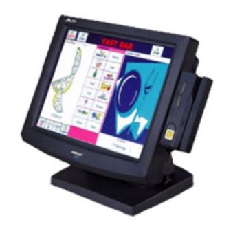
LM4115 / TM4115
LCD / Touch Monitor
USER'S MANUAL
Rev. : Original
I.
FEATURES
•
Most stable touch monitor for industrial and commercial use
•
Application covers POS, POI (Kiosk), -Factory Automation etc.
•
High quality 15" TFT LCD panel with scaling function for full screen display
•
Spill proof and easy maintenance structure allowing easy cleaning
•
Tilt adjustable yet robust and wobble free construction
•
Recommended. LCD resolution: 1024 x 768
•
Slim featured from any excessive option for its predecessor
•
Resistive type extra long life touch panel
•
Touch functions include left/right button, double click, drag & drop (for TM4115 only)
•
Touch beep can be pitch adjusted and enabled/disabled by software control (TM only)
•
Connect to host through VGA and COM port
FCC NOTICE
This equipment generates, uses, and can radiate radio frequency energy and, if not installed and used in
accordance with the instructions manual, may cause interference to radio communications. It has been tested and found to
comply with limits for a Class A digital device pursuant to subpart J of Part 15 of FCC Rules, which are designed to
provide reasonable protection against interference when operated in a commercial environment. Operation of this
equipment in a residential area is likely to cause interference in which case the user at his own expense will be required to
take whatever measures to correct the interference.
WARRANTY LIMITS
Warranty will terminate automatically when the machine is opened by any person other than the authorized
technicians. The user should consult his/her dealer for the problem happened. Warranty voids if the user does not follow
the instructions in application of this merchandise. The manufacturer is by no means responsible for any damage or
hazard caused by improper application.
ABOUT THIS MANUAL
This manual assists the user to utilize the LCD Monitor LM4115 and the TOUCH Monitor TM4115. This
product provides exquisite touch control capability over a stable and adjustable LCD monitor with minimal footprint.
The manufacturer of the LM4115 / TM4115 LCD / touch monitor heartily apologizes to the user for reserving
the right to change or to modify this manual without notice due to the rapid and constant progress and improvement on
science and technology. The user may always obtain the most up to date information through any of our web sites:
http://www.posiflex.com.tw, http: //www.posiflexuk.com, http://www.posiflexusa.com.
TRADE MARKS AND SERVICE MARKS
POSIFLEX is a registered trademark of Posiflex Inc..
Other brand and product names are trademarks and registered trademarks and service marks of their respective
owners.
19640900000
P/N:
© Copyright Posiflex Inc. 2004
1
Advertisement
Table of Contents

Related Manuals for POSIFLEX LM4115


Summary of Contents for POSIFLEX LM4115
- Page 1 LCD monitor with minimal footprint. The manufacturer of the LM4115 / TM4115 LCD / touch monitor heartily apologizes to the user for reserving the right to change or to modify this manual without notice due to the rapid and constant progress and improvement on science and technology.
-
Page 2: Carton Contents
3. Plastic key for cable cover latch 4. VGA cable: 20863136610 5. RS232 cable: 20863244210 (for TN4115 only) 6. Posiflex Product Information CDROM (for TM4115 only) 7. Power adaptor: 12 V DC ASP0P042WTB001 & power cord III. PARTS IDENTIFICATION A. FRONT VIEW... -
Page 3: Rear View
C. REAR VIEW Lock/release button to detach the main unit Cable cover Lock/release lever for tilt angle adjust Cable Exit IV. INPUT / OUTPUT PORTS (RS232) RJ45 Jack (for TM4115 only) 12 V DC V. AVAILABLE OPTION ITEMS 1. Wall Mount Kit 2. -
Page 4: Driver Installation
VIII. DRIVER INSTALLATION A. INSTALLATION (for TM4115 touch control) Please find in the attached Posiflex product information CDROM under subdirectory \Drivers\TM4_TM6\RS232 or \Drivers\TM4000\RS232 for RS232 interface touch controller driver. In case this subdirectory is not found in the CDROM received, please use identical driver from relevant product such as \Drivers\TP6000\Touch\RS232. - Page 5 during the installation process. Same approach applies for other operating system. If, for any reason, the user wants to remove the driver for the RS232 touch controller, please select “Monitor Mouse” in the program list for removal. B. SETUP/CALIBRATION (for TM4115 touch control) Once the RS232 touch controller driver is installed, the user can utilize it to calibrate the touch screen, define mouse button emulation modes, enable right button emulation or define the click sound’s tone and duration.
-
Page 6: Led Indication
OSD functions (On Screen Display adjustment). The OSD window will pop up on the screen. On top part of this window is a Posiflex logo with the OSD firmware version indicated to its lower right. Below this area is a row of icons for main OSD menu. - Page 7 signal on resolution and refresh rate will be displayed at the bottom. Applicable icons in the main menu and its subsequent menus are explained below. “MAIN MENU”: There are in total 5 icons in this menu: One of the 5 icons will be displayed in inverted color to indicate its relationship with the submenu below.
- Page 8 “AUTO RGB RESET”: Upon an “OSD” button press on this icon the monitor will perform an automatic RGB reset and exits the OSD window leaving 2 icons below at center of the screen. Press “NXT” button to switch the selection. Press “OSD” button to make the choice. “ACCEPT”: Accept the reset result.
- Page 9 “AUTO GEOMETRY ADJUST”: Upon an “OSD” button press on this icon the monitor will perform an automatic geometry adjustment and exits the OSD window leaving 2 icons below at center of the screen. Press “NXT” button to switch the selection. Press “OSD” button to make the choice.
- Page 10 main menu. Press “NXT” button to select among OSD time, OSD horizontal position, OSD vertical position and exit. “OSD TIME”: When this item is selected, there will be only the OSD time icon with an adjustment indication bar under it between the main menu area and the video signal mode.
-
Page 11: Supported Display Modes
and pixel frequency of 31.5MHz making it impossible for automatic select. These modes are not used in normal Windows display. “EXIT”: Return to “Main menu”. “EXIT”: Exit OSD setup with all adjustment saved. SUPPORTED DISPLAY MODES For video signals beyond the supported display modes, there will be a message “Out Of Range”...
Need help?
Do you have a question about the LM4115 and is the answer not in the manual?
Questions and answers