Table of Contents
Advertisement
Quick Links
LM-6101E Series
LCD Monitor
USER'S MANUAL
Rev. : Original
FCC NOTICE
This equipment generates, uses, and can radiate radio frequency energy and, if not installed and used in accordance with
the instructions manual, may cause interference to radio communications. It has been tested and found to comply with
limits for a Class A digital device pursuant to subpart J of Part 15 of FCC Rules, which are designed to provide
reasonable protection against interference when operated in a commercial environment. Operation of this equipment in a
residential area is likely to cause interference in which case the user at his own expense will be required to take whatever
measures to correct the interference.
WARRANTY LIMITS
Warranty will terminate automatically when the machine is opened by any person other than the authorized technicians.
The user should consult his/her dealer for the problem happened. Warranty voids if the user does not follow the
instructions in application of this merchandise. The manufacturer is by no means responsible for any damage or hazard
caused by improper application.
ABOUT THIS MANUAL
This manual assists the user to utilize the LCD Monitor LM-6101E. These series provide versatile font formats and
support various instruction sets. These series of products receive instructions in serial communication protocols and is
capable of entering pass through mode so that all instructions received pass on to next connected serial device if properly
configured.
The manufacturer of the LM-6101E series heartily apologizes to the user for reserving the right to change or to modify
this manual without notice due to the rapid and constant progress and improvement on science and technology. The user
may always obtain the most up to date information through any of our web sites:
http://www.posiflex.com.tw, http: //www.posiflexuk.com, http://www.posiflexusa.com.
TRADE MARKS AND SERVICE MARKS
All brand and product names and trademarks are the property of their respective holders.
© Copyright Posiflex Technology, Inc. 2016
P/N: 19650902010
1
Advertisement
Table of Contents

Subscribe to Our Youtube Channel
Related Manuals for POSIFLEX LM-6101E Series


Summary of Contents for POSIFLEX LM-6101E Series
-
Page 1: Lcd Monitor
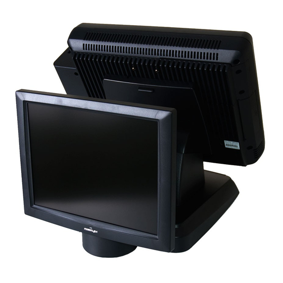
The manufacturer of the LM-6101E series heartily apologizes to the user for reserving the right to change or to modify this manual without notice due to the rapid and constant progress and improvement on science and technology. The user may always obtain the most up to date information through any of our web sites: http://www.posiflex.com.tw, http: //www.posiflexuk.com, http://www.posiflexusa.com. - Page 2 • High-quality 12” TFT LCD panel with scaling up function for full screen display. • Resolution: 1024 x 768. • Tilt and swivel adjustable construction for LM-6101E series. • Easy maintenance structure allowing easy cleaning. • LM-6101E is a 12.1” LCD monitor with tilt adjust for 2 display attached to FT/TP series POS system.
-
Page 3: Osd Menu Introduction
2. Aim the 2 holes of LM-6101E to the 2 holes of the 5 Gen base for Posiflex TP-8000/TP-8300 terminal per instruction of the terminal. Then Fix the terminal onto the 5 Gen base with the 2 screws. LM-6101E Pivot Screw Gen5 base 3. - Page 4 B. Power & OSD buttons The buttons at the right side of LCD monitor are for the OSD (On Screen Display) control operations and LCD screen power control as in the right picture and are explained below. “OSD” button: To enter OSD menu. “EXT”...
- Page 5 C. OSD Options The OSD options are provided for you to do easy setting of the LCD monitor. Please refer to the following table for further explanation of those accessible items in the LM-6101E‘s OSD. OSD Menu Options Sub-menu items & Description ...
- Page 6 OSD Menu Options Sub-menu items & Description Pixel Clock Use the “+” or “-” button to adjust the Clock setting for VGA input. Phase Use the “+” or “-” button to adjust the Phase setting for VGA input. ...
- Page 7 SUPPORTED DISPLAY MODES For VGA signals beyond the supported display modes, there will be a message “Out Of Range” on the middle of screen. Maximum supported color depth is 18 bits or 262,144 colors. Supported display modes are illustrated in the table: Horizontal Display Resolution Refresh Rate (Hz)
- Page 8 <MEMO>...
Need help?
Do you have a question about the LM-6101E Series and is the answer not in the manual?
Questions and answers