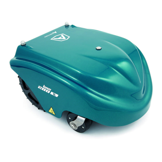
AMBROGIO BASIC User Manual

AMBROGIO BASIC User Manual

Lawn mower robot
Hide thumbs Also See for BASIC:

Advertisement

Congratulazioni per aver acquistato il rasaerba AMBROGIO. L'aver
scelto questo prodotto potrà soddisfare le vostre esigenze e
aspettative. Questo progetto nasce da ZUCCHETTI CENTRO
SISTEMI S.p.A. (Azienda certificata UNI EN ISO 9001) software
house che, dal 1982, ha consolidato la propria attività e la
propria presenza sul mercato internazionale. Le soluzioni
applicative del software abbinate al settore industriale di
automazione, fanno nascere prodotti nuovi che ottimizzano le
procedure di lavoro. È così che è nato, dai laboratori di ricerca,
AMBROGIO.
Congratulations for having purchased the AMBROGIO lawn
mower. This choice will surely meet your needs and
expectations. This product is the result of research at the
ZUCCHETTI CENTRO SISTEMI S.p.A. (certified UNI EN ISO
9001) software house that, since 1982, has been
consolidating its role on the international market. Innovative
software solutions applied to the industrial automation sector
introduce new products that optimise working procedures.
AMBROGIO was developed on the basis of this research.
Tous nos compliments pour avoir acheté la tondeuse à gazon
AMBROGIO. Vous avez choisi un produit qui répondra à vos
besoins et à vos attentes. Ce projet naît au ZUCCHETTI CENTRO
SISTEMI S.p.A. (Entreprise certifiée UNI EN ISO 9001) software
house qui, depuis 1982, a consolidé son activité et sa présence
sur le marché international. Les solutions d'application du
logiciel, jumelées au secteur industriel d'automation, ont permis
la naissance de nouveaux produits qui optimisent les
procédures de travail. C'est ainsi que, dans nos laboratoires de
recherche, est né AMBROGIO.
Wir gratulieren zum Kauf des Rasenmähers AMBROGIO. Ihre
Bedürfnisse und Erwartungen werden durch die Wahl dieses
Produkts mit Sicherheit erfüllt. Die Firma ZUCCHETTI CENTRO
SISTEMI S.p.A. (mit UNI EN ISO 9001 ausgezeichneter Betrieb)
Software House, die ihre Produktion seit 1982 festigt und
damit auf dem internationalen Markt vertreten ist, zeichnet für
dieses
Produkt
verantwortlich.
Softwarelösungen führen in Kombination mit der industriellen
Automatisierung zur Entstehung neuer Produkte für eine
Optimierung von Arbeitsprozessen. Auf diese Weise entstand
in den Forschungslabors AMBROGIO.
Felicidades por haber adquirido la cortadora de césped
AMBROGIO. Podrá satisfacer sus exigencias y expectativas al
haber elegido este producto. Este producto nace de
ZUCCHETTI CENTRO SISTEMI S.p.A. (Empresa certificada UNI
EN ISO 9001) software house que, desde 1982, ha
consolidado su propia actividad y su propia presencia en el
mercado internacional. Las soluciones de aplicación del
software
combinadas
con
automatizando, hacen nacer nuevos productos que optimizan
los procedimientos de trabajo. Es así que ha nacido, en los
laboratorios de investigación, AMBROGIO.
Wij wensen u van harte geluk met de aanschaf van uw
AMBROGIO. Wij zijn er zeker van dat deze machine voldoet aan
al uw verwachtingen en vereisten. AMBROGIO is een project
van ZUCCHETTI (met UNI EN ISO 9001 certificaties), een
softwarebedrijf dat sinds 1982 met haar activiteiten een eigen
plaats verwierf op de internationale markt. De combinatie van
de
oplossingen
die
softwaretoepassingen en de industriële automatisering
resulteert in nieuwe producten om de bedrijfsprocessen te
optimaliseren. Zo ontstond in onze onderzoekscentra
AMBROGIO.
Die
angewandten
el
sector
industrial
de
worden
geboden
door
Manuale d'uso
Rasaerba Robot
User's manual
Lawn Mower Robot
Manuel d'utilisation
Tondeuse à gazon Robot
Bedienungshandbuch
Rasenmähroboter
Manual de uso
Cortadora de césped Robot
Gebruiksaanwijzingen
Grasmaaimachine
I
Italiano
GB
English
F
Français
D
Deutsch
E
Español
NL
Nederlands

Advertisement

Table of Contents
loading
Need help?

Need help?

Do you have a question about the BASIC and is the answer not in the manual?

Questions and answers

Summary of Contents for AMBROGIO BASIC

  • Page 1 AMBROGIO. Wij wensen u van harte geluk met de aanschaf van uw AMBROGIO. Wij zijn er zeker van dat deze machine voldoet aan al uw verwachtingen en vereisten. AMBROGIO is een project van ZUCCHETTI (met UNI EN ISO 9001 certificaties), een softwarebedrijf dat sinds 1982 met haar activiteiten een eigen plaats verwierf op de internationale markt.
  • Page 2 Dichiarazione di conformità (98/37 CE allegato II punto A) Konformitätsbestätigung (98/37 CE Beilage II Punkt A) ZUCCHETTI Centro Sistemi S.p.A. Via dell’Olmo 99 A/B Die Firma ZUCCHETTI Centro Sistemi S.p.A., Via dell’Olmo 99 Terranuova B.ni (AR) ITALIA, dichiara che la macchina, A/B Terranuova B.ni (AR) ITALIEN, erklärt, daß...
  • Page 3: Table Of Contents

    CONTENTS GENERAL INFORMATION ......4 USE AND FUNCTIONING ......29 TECHNICAL INFORMATION ......5 ORDINARY MAINTENANCE ...... 48 SAFETY INFORMATION ........9 FAILURES, CAUSES AND SOLUTIONS .. 50 INSTALLATION ..........11 PARTS REPLACEMENTS ......55 ADJUSTMENTS ..........27 ANALYTICAL CONTENTS Adjusting the cutting height, 28 Rain sensor adjustment, 29 Adjustment reminders, 27...
  • Page 4: General Information

    GENERAL INFORMATION PURPOSE OF THIS MANUAL The constructor has produced this man- The manufacturer reserves the right to ual, which forms an integral part of the make all necessary changes without pri- appliance, to provide the necessary infor- or notice of any kind. mation for those authorised to interact The following symbols are used through- with it during its working life.
  • Page 5: Technical Information

    TECHNICAL INFORMATION EQUIPMENT GENERAL DESCRIPTION The appliance Ambrogio Line 200 is a robot designed and built to automatically trim grass in gar- dens and house lawns in any time of the day. It is small, compact, si- lent, waterproof and easy to transport.
  • Page 6 The robot Ambrogio Line 200 is pro- Main parts duced in the BASIC, DELUXE and EVOLU- – Accumulator batteries (A): they en- TION versions. ergize the motors of the blade and of BASIC version: basic model which can the wheel control system.
  • Page 7: Specifications

    (N) Perimeter wire sensor (Q) cutting blade (E) electronic card (C) electric motor (G) IDM - 41501700300.tif SPECIFICATIONS Model Description BASIC DELUXE EVOLUTION Cutting blade 4 (mm) Cutting speed (m/min) Cutting height 20-60 20-60 20-60 (mm) Maximum gradient of the surface 27°...
  • Page 8 Model Description BASIC DELUXE EVOLUTION Battery accumulator recharge type battery accumulators (lead) (V/A) 27,6V - 4A battery accumulators (lithium) 29,3V - 4A 29,3V - 4A 29,3V - 4A (V/A) Maximum surface that can be trimmed Robot with two lead batteries...
  • Page 9: Safety Information

    Model Description BASIC DELUXE EVOLUTION Battey charger kit (winter period on request on request on request or extended inactivity) Wheels with "nailed" tread on request on request on request Wheels with "claws" profile tread on request on request on request (1) If the ground conditions are suitable (solid, without excessive folds, etc.), the kit allows the robot to work (within...
  • Page 10 – Never tamper with, avoid, remove or – Always remove the blade before re- bypass installed safety devices. Such placing the batteries. actions could lead to serious risk to – In order not to irreversibly damage personal health and safety. electric and electronic parts, do not –...
  • Page 11: Installation

    SAFETY SIGNALS Danger signal: indicates Safety signal: indicates that the user should not ap- that the user should care- proach to the blades while fully read the manual be- the lawn mower is operat- fore operating the lawn ing. mower. INSTALLATION PACKAGING AND UNPACKING The machine is delivered suitably pack-...
  • Page 12: Equipment Installation Planning

    EQUIPMENT INSTALLATION PLANNING Robot installation does not involve inter- the charging station, power supply-trans- ventions that are difficult to carry out, mitter group and to lay out the perime- but requires a minimum of preliminary ter wire. planning to define the best area to install Power supplier-transmitter power supply-transmitter unit...
  • Page 13 Warning - Caution Important To carry out electric connection, it is To permit the robot to re-enter the re- necessary to arrange a power supply charging station, it is necessary to in- socket near the installation area. Make stall the same within the work area sure that the connection to the power having larger dimensions, hereafter re- supply complies to the laws in force on...
  • Page 14 PREPARATION AND DELIMITATION OF WORK AREAS (MAIN AND SECONDARY) Arrangement of lawn to trim 1-Check that the lawn to trim is even, and without pits, stones or other obstacles. If so, per- form the necessary clearance operations. If some obstacles cannot be removed, it is necessary to properly mark the areas in- volved.
  • Page 15 Important To ensure the robot can operate, it is necessary for the distance passage aisle separating the delimitation of two elements to be greater than 70 cm. This distance is required house to permit robot passage. When the connection between one surface and another of the MAIN AREA SECONDARY...
  • Page 16 4-Mark and trace the perime- ters of the inside and marginal manhole elements of the working area that obstruct the correct func- tioning of the robot. Important The figure represents an exam- ple of inside an marginal ele- ments of the working area and the distances that must be re- spected for the tracing of the un- derground...
  • Page 17: Perimeter Wire Installation

    5-Mark the areas, located in a lower position compared to pool elevated area the lawn surface (pools, areas perimeter wire with significant drops, stairs, etc.) (see example in figure). Important Strictly respect the distances to avoid that the robot falls with the risk of breaking and/or seriously getting damaged.
  • Page 18 Wire laid on the ground 1-Place the wire clockwise along the whole path and fix it with the appropriate nails supplied wire fixing nails (distance between the nails 1÷2 m). – When positioning the perimter wire, respect the rotation di- perimeter wire rection around the bays (anti- clockwise).
  • Page 19 Perimeter wire joint Important In the case of underground wire as well as of ground laid wire, if necessary, properly join it with some other wire, having the same features (see figure). During the joint stage, it is rec- ommended to use self-amalga- mating tape (for example: 3M Scotch 23).
  • Page 20 INSTALLATION OF RECHARGING STATION AND TRANSMITTER-POWER SUPPLIER GROUP 1-Identify the recharging station power supply unit (A) installation area and the trans- mitter-power supply group. Warning - Caution Before carrying out any interven- tion deactivate the general elec- tricity power supply. 2-Installation of the power sup- ply-transmitter unit (A-B).
  • Page 21 4-Position the base in the prede- Black terminal Red terminal fined area. 5-Insert the perimeter wire (M) under the base. perimeter wire (M) IDM - 41501701600.tif 6-Connect the two ends of the Red terminal Black terminal wire to the terminals of the base.
  • Page 22 8-Reposition the shield (L). guard (L) IDM - 41501701500.tif 9-Connect the power supply ca- cursor (C) ble (E) of the recharging sta- tion (F) to the transmitter (B). pushbutton (D) 10-Operate on the cursor (C) to select the power supply volt- led (H) age (110 V or 220 V).
  • Page 23: Battery Installation And Connection

    BLADE INSTALLATION 1-Before assembling and/or re- placing the blade, make sure that the robot has been stopped in safety conditions blade (A) (see "Robot safety stop"). 2-Turn the robot upside down and put it down so not to ruin the covering hood. Important Use protection gloves to avoid the risk of cuts on hands.
  • Page 24 2-Remove the hood (B). hood (B) IDM - 41501702000.tif 3-Undo the bolts (C) and remove the guard (D). screw (C) guard (D) screw (C) screw (C) IDM - 41501702100.tif 4-Unscrew the nuts (E) and un- bracket (F) thread the brackets (F). bracket (F) nut (E) IDM - 41501702200.tif...
  • Page 25 5-Insert the batteries (G) in the appropriate positions. battery (G) battery (G) IDM - 41501702300.tif 6-Assemble the brackets (F) bracket (F) complete with batteries. 7-Tighten the nuts (E). bracket (F) Important The connection must be carried nut (E) out in accordance with the pro- cedures given, relative to the type of battery installed (lead or lithium).
  • Page 26 Lithium battery connection LITHIUM BATTERY 1-Connect the connector (P) connector (R) connector (P) (black colour with black cable) 2-Connect the connector (Q) connector (Q) (red colour with red cable) 3-Connect the connector (R) (red colour with red cable) (on- ly when installing 2 lithium bat- teries).
  • Page 27: Adjustments

    At this point, the robot is ready to use Important (see "Use and functioning"). Before using the robot, perform a com- plete recharge of the new batteries (see "Recharge batteries on first use"). RECHARGE BATTERIES ON FIRST USE 1-Insert the robot inside the re- charging station.
  • Page 28: Adjusting The Cutting Height

    ADJUSTING THE CUTTING HEIGHT Before setting the cutting height of the blade, make sure that the robot has stopped in safety conditions (see "Robot safety stop"). 1-Disenable the antitheft alarm to avoid activation (see "Pro- gramming mode"). Important blade (A) Use protection gloves to avoid the risk of cuts on hands.
  • Page 29: Use And Functioning

    RAIN SENSOR ADJUSTMENT 1-Stop the robot in safety condi- tions (see "Robot safety stop"). 2-Adjust the distance between the pins (A-B) via rotation of pin (B) the pin (A). eccentric pin Important The sensitivity of the sensor in- creases with a decrease in the distance between the pins.
  • Page 30: Robot Controls Description

    ROBOT CONTROLS DESCRIPTION The figure shows the control position on OFF/STOP: press to stop the lawn machine board. mower; the display turns off. Display: shows all functions. Key "+": when working, press to ON: press to turn on the lawn mower. restart the previously stopped blade.
  • Page 31: Programming Mode

    REMOTE CONTROL DESCRIPTION – Push buttons (A-B): they are used to make the robot bend towards right or left. pushbutton The robot keeps on bending to- “Start/Pause” (C) wards a direction or the other un- til the relating push button (right Left arrow (A) or left) is kept pressed.
  • Page 32 The "ALARM" func- To switch off the alarm it is necesary to tion appears on the proceed as indicated. display. 2-Switch on the robot. 3-Access the "ALARM" function. 4-Press one of the keys "+", "-" to dis- play "Disenable". Important 5-Insert the password (see "Enter To memorise the function displayed, password").
  • Page 33 5-Press one of the 1-Press one of the keys "+", "-" to set keys "+", "-" to the year. programme the weekdays when the robot is oper- ational. 6-Press the key "En- Value 0: day of rest for the robot. ter"...
  • Page 34 5-Press one of the On the display the keys "+", "-" to set "WORK TIMETABLE the mowing end 2" function appears. time. 6-Press the key "En- WORK TIMETABLE 2: function for set- ter" to confirm. ting the second robot activity time slot cursor during the day.
  • Page 35 the robot immediately after rapid re- 9-Press the key to entry setting. confirm. 4-Press the "+" Key and the "-" Key to enter the number Important of work cycles to If secondary areas are provided (type 1 perform in the or 2), to complete the field of functions main area, the lawn mower starts relative to the number of cycles and time...
  • Page 36 Select ×4 if the problem is not solved by 1-Press "+" and "-" to disable this op- selecting ×2. tion or set the percent of mowed Select ×6 if the problem is not solved by lawn grass to be used for auto-pro- selecting ×4.
  • Page 37 6-Press at the same time the keys "DX", "SX" of the telecom- mnad within 10 seconds (see figure). Left arrow (SX) Activation of a double sound in- dicates that robot and tele- command matching occurred. 7-Press the key "Enter" to con- firm.
  • Page 38: Automatic Cycle Start

    11-Press one of the PASSWORD STARTING: function for keys "+", "-" to set programming or not the password in- the first number. sertion request each time the robot is switched off and restarted after a peri- od of inactivity (example, remessage for winter season).
  • Page 39: Robot Automatic Stop

    functions correspond to the effective Important status of the surfaces to be mown (e.g. addition of a swimming pool, If the antitheft alarm is enabled, disen- plants etc.) (see "Programming able it before lifting the robot (see mode"). "Programming mode"). 4-Adjust the cutting height (see "Ad- 7-After some seconds, on the display justing the cutting height").
  • Page 40: Manual Startup And Stop Of Robot (In Closed Areas)

    MANUAL STARTUP AND STOP OF ROBOT (IN CLOSED AREAS) Start-up of the robot in manual mode must be carried out to mow areas that are not included in the programming of surfaces to be mown in automatic modality. Place the robot inside the working area at least 1 m far from the pe- rimeter wire and from any other obstacle.
  • Page 41: Robot Start Without Perimeter Wire

    ROBOT START WITHOUT PERIMETER WIRE This mode can be carried out with the remote control to perform the Key “ON” (A) Key “Start/Pause” (B) trimming of areas completely marked by fences or to trim, for example, small areas, where it was not possible to mark or for practical demonstrations on the functioning of the robot...
  • Page 42: Display Visualisation In Work Phase

    ENTER PASSWORD The robot can be protected by a pass- 3-Press the key "En- word comprising four figures which the ter" to confirm. user can enable, disenable and custom- cursor ise (see "Programming mode"). moves on to the next position. 1-The following message...
  • Page 43 4-Disconnect the plug of the power supply unit (A) power supply unit (A). pushbutton (B) 5-Cover the recharging station (C) to prevent any material en- tering it (leaves, paper etc.) and to protect the contact plates. Service restart Before restarting the robot after a long inactivity, proceed as shown.
  • Page 44: Recharge Batteries For Extended Inactivity

    RECHARGE BATTERIES FOR EXTENDED INACTIVITY Carry out battery recharge at least once a month for lead bat- “ON” (A) teries and every 5 months for lith- ium batteries. 1-Power the recharging base and make sure that the plates are clean. Important If the antitheft alarm is enabled, disenable it before lifting the ro-...
  • Page 45 Batteries reset with winter re- power supply unit (A) charging kit (optional) The kit makes it possible to re- pushbutton (D) charge the batteries or keep them charged, during the winter period, without using the recharging sta- tion. 1-Press the button (D) of the power supply unit on OFF.
  • Page 46 8-Press key ON (G). 9-Insert the password (if re- red connector “ON” (G) quested) (see "Enter pass- word"). black connector (L) “Off/Stop” (M) IDM - 41501710900.tif 10-The following 14-the following mes- message sage appears of pears of the dis- the display: play: batteries start the recharging cycle.
  • Page 47 Once the winter season has end- "Winter recharging kit" ed, disconnect the kit and reacti- cable (F) vate the recharging station. pushbutton (D) 1-Press the button (D) of the power supply unit on OFF. 2-Disconnect the plug of the power supply unit (A). 3-Disconnect the cable (F) from the transmitter group (B).
  • Page 48: Maintenance Reminders

    OPERATING REMINDERS Here below are some indications to fol- the robot so that it re-enters the re- low during the use of the robot. charging station at least 1 hour be- – Even after a proper reading of instruc- fore the start of irrigation. tions, at its first use, simulate some –...
  • Page 49: Robot Cleaning

    ROBOT CLEANING 1-Stop the robot in safety conditions 5-Check the lower part of the robot (see "Robot safety stop"). (cutting blade area and wheels) and remove the deposits and/or resi- Important dues that might obstruct the correct functioning of the robot. If the antitheft alarm is enabled, disen- able it before lifting the robot (see 6-To remove the deposits and/or oth-...
  • Page 50: Failures, Causes And Solutions

    FAILURES, CAUSES AND SOLUTIONS TROUBLESHOOTING The information given below is designed er; others require precise technical skills to help identify and correct any faults or special abilities and must be exclusive- and malfunctions that may occur during ly resolved by qualified personnel with operation.
  • Page 51 Problem Causes Solutions Replace the blade with a new Damaged cutting blade one (see "Replace the blade") Stop the robot in safety condi- tions (see "Robot safety stop") Caution Cutting blade flooded by Use protection gloves to residues (tapes, ropes, avoid the risk of cuts on plastic fragments, etc.).
  • Page 52 Problem Causes Solutions Extend the work timetable Insufficient work hours (see "Programming mode") Stop the robot in safety condi- tions (see "Robot safety stop") Caution Cutting blade with deposi- Use protection gloves to ts and/or residues avoid the risk of cuts on hands.
  • Page 53 Problem Causes Solutions Mark the area with excessive gradient (see "Equipment in- stallation planning"). Excessive ground slope. Install the Kit for working on slopes greater than 27° (see "Specifications"). Check that the wire is instal- led properly (too deep, close to metal objects, distance Perimeter cable incor- between the wire that marks...
  • Page 54 Problem Causes Solutions Switch off the equipment and On the display The robot receiver does switch it on again. "Sync Error" appe- not recognise the signal If the problem persists, con- tact the assistance service Replace the blade with a new Damaged cutting blade one (see "Replace the blade") Stop the robot in safety condi-...
  • Page 55: Parts Replacement Reminders

    Problem Causes Solutions Check that the position of the cursor (B) matches with the power voltage and that the There is no power volta- push button (A) is on "ON". The led (D) of the Check that the power supply power supply unit unit is correctly connected to does not turn on.
  • Page 56: Batteries Replacement

    BATTERIES REPLACEMENT 1-Stop the robot in safety condi- tions (see "Robot safety stop"). Recharging knobs (A) 2-Undo the knobs (A). IDM - 41501701900.tif 3-Remove the hood (B). hood (B) IDM - 41501702000.tif 4-Undo the bolts (C) and remove the guard (D). screw (C) Important Batteries replacement should be...
  • Page 57 Lead battery LEAD BATTERY 1-Disconnect the cables in se- connector (M) connector (H) quence (L-N-M-H). connector (L) connector (N) IDM - 41501702500.tif 2-Unscrew the nuts (E) and un- bracket (F) thread the brackets (F). bracket (F) nut (E) IDM - 41501702400.tif 3-Remove the battery (G) and fit battery (G) the replacement.
  • Page 58 5-Assemble the brackets (F) bracket (F) complete with batteries. 6-Tighten the nuts (E). bracket (F) nut (E) IDM - 41501702400.tif 7-Connect the connector (H) LEAD BATTERY (red colour with blue) connector (M) connector (H) 8-Connect the connector (L) (red colour with red cable) connector (L) 9-Connect the connector (M) (black colour with blue cable)
  • Page 59 2-Unscrew the nuts (E) and un- bracket (F) thread the brackets (F). bracket (F) nut (E) IDM - 41501702400.tif 3-Remove the battery (G) and fit the replacement. battery (G) 4-Perform the same operations to replace the other battery (G) (if present). Important Do not dump used batteries.
  • Page 60 7-Connect the connector (P) LITHIUM BATTERY (black colour with black cable) connector (R) connector (P) 8-Connect the connector (Q) (red colour with red cable) connector (Q) 9-Connect the connector (R) (red colour with red cable) 10-Connect the connector (S) (black colour with black cable) connector (S) IDM - 41501702600.tif On completing the batteries con-...
  • Page 61: Replace The Blade

    4-Position the robot inside the recharg- suitable for the type of batteries in- ing station. stalled (power supply unit for lead or lithium batteries) (see "Recharge bat- 5-Carry out battery recharge. teries on first use"). Warning - Caution At this point, the robot is ready to use Before performing the first recharge, (see "Use and functioning").
  • Page 62: Robot Disposal

    TELECOMMAND BATTERIES REPLACEMENT THE BLADE 1-Stop the robot in safety condi- tions (see "Robot safety stop"). 2-Remove the cover (A). cover (A) 3-Extract the battery (B) and re- place it with one of equal volt- Important When reassembling the new bat- tery respect the relative polari- ties (+ e -).

This manual is also suitable for:

DeluxeEvolutionL200 evolutionL200 deluxe

Table of Contents

Save PDF