Table of Contents
Advertisement
Quick Links
Download this manual
See also:
Operator's Manual
Advertisement
Table of Contents

Related Manuals for SteelMax SM-D1


Summary of Contents for SteelMax SM-D1
- Page 1 The tools of innovation. OPERATOR’S MANUAL DRILLING MACHINE WITH ELECTROMAGNETIC BASE 112 Inverness Circle East Suite F Englewood, CO 80112 1– 87STEELMAX, FAX 303 – 690 – 9172 www.steelmax.com sales@steelmax.com...
-
Page 2: Table Of Contents
Contents 1. GENERAL INFORMATION ....................3 1.1. Application ......................... 3 1.2. Technical data......................3 1.3. Equipment included ....................4 1.4. Dimensions ........................ 5 1.5. Design ........................5 2. SAFETY PRECAUTIONS ....................6 3. STARTUP AND OPERATION ................... 8 3.1. Installing and removing the handle ................8 3.2. -
Page 3: General Information
1. GENERAL INFORMATION 1.1. Application The SM-D1-LP is a drilling machine with electromagnetic base, designed to drill holes with diameters of up to 36 mm (1-7/16’’) either to a depth of up to 20 mm (13/16’’) by using HSS annular cutters or to a depth of up to 30 mm (1-3/16’’) by using TCT annular cutters. -
Page 4: Equipment Included
1 unit Handle adapter 1 unit Pilot pin 7.98x85 for TCT cutters 1 unit Pilot pin 6.34x74 for HSS cutters 1 unit Safety strap 1 unit 4 mm hex wrench 1 unit – Operator’s Manual 1 unit SM-D1-LP Operator’s Manual... -
Page 5: Dimensions
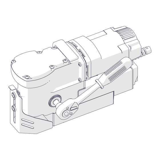
147 mm (5-13/16’’) 380 mm (14-15/16’’) 1.5. Design TCT quill assembly including spindle with arbor Carrying handle Control panel MOTOR start button MOTOR stop button Electromagnetic base (MAGNET) switch Chip guard Opening for safety strap Electromagnetic base SM-D1-LP Operator’s Manual... -
Page 6: Safety Precautions
17. Never use annular cutters without a pilot pin except when drilling incomplete through holes. 18. Never use near flammable liquids or gases, or in explosive environments. 19. Never use the machine on surfaces that are rusty, covered with a thick paint layer, uneven, or not rigid. SM-D1-LP Operator’s Manual... - Page 7 30. Never leave the machine unattended during work. 31. Remove from the worksite and store in a secure and dry place when not in use, previously removing the tool from the holder. SM-D1-LP Operator’s Manual...
-
Page 8: Startup And Operation
Install the handle by using the adapter as shown in Fig. 1. The handle can be installed from the opposite side of the machine to allow working in places hard to reach or using the machine by a left-handed person. To remove the handle, pull it out. Fig. 1. Installing the handle SM-D1-LP Operator’s Manual... -
Page 9: Installing, Removing, And Operating The Annular Cutter
(5) are aligned with the set screws (2), and then use the 4 mm hex wrench to tighten both set screws. To remove the cutter, loosen the screws (2) with the 4 mm hex wrench. Fig. 2. Installing the annular cutter SM-D1-LP Operator’s Manual... - Page 10 Annular cutters are designed to make only through holes shown in Fig. 4. When drilling incomplete through holes the pilot pin must not be used. Incomplete through holes Complete through holes Fig. 4. Types of holes to make with annular cutter SM-D1-LP Operator’s Manual...
-
Page 11: Preparing
Fig. 5c), and must be replaced every single time the machine hangs on the strap as a result of coming loose from steel. Never insert the strap into the buckle from the front (Fig. 5d). SM-D1-LP Operator’s Manual... - Page 12 When drilling in vertical positions (Fig. 5a), apply the coolant manually into the drilling area. When drilling in inverted or horizontal positions (Fig. 5b, 5c) use coolants under pressure or in the form of spray or paste. SM-D1-LP Operator’s Manual...
-
Page 13: Drilling
Before inserting the machine into the box, remove the handle, and then wear gloves to remove the tool from the holder. SM-D1-LP Operator’s Manual... -
Page 14: Replacing The Motor Brushes
5 mm (3/16’’), replace both brushes with new ones. To install brushes, proceed in reverse order. After the replacement, run the motor without load for 20 minutes. Fig. 6. Replacing the brushes SM-D1-LP Operator’s Manual... -
Page 15: Accessories
4.2. HSS quill assembly Allows you to drill holes to a depth of up to 25 mm (1’’) by using HSS annular cutters or twist drill bits with a 19 mm (3/4’’) Weldon shank. Part number: ZSP-0521-04-00-00-0 SM-D1-LP Operator’s Manual... - Page 16 (2), and then push out the shaft (3) by 16 mm (10/16’’), which will expel the TCT quill assembly (4). Insert the HSS quill assembly (5), push in the shaft (6), and then place the retaining rings back in place (7). Fig. 7. Installing the HSS quill assembly SM-D1-LP Operator’s Manual...
-
Page 17: Wiring Diagram
SM-D1-LP 5. WIRING DIAGRAM SM-D1-LP Operator’s Manual... -
Page 18: Exploded Drawings And Parts List
SM-D1-LP 6. EXPLODED DRAWINGS AND PARTS LIST ITEM PART NUMBER DESCRIPTION Q-TY SKR-000012 PLASTIC BOX PLT-0521-11-00-00-0 PILOT PIN 7.98x85 KLC-000007 4 MM HEX WRENCH PRD-000002 TORQUE STICK KLC-000048 RATCHET WRENCH 3-8 PLT-0378-15-00-00-0 PILOT PIN 6.34x74 SM-D1-LP Operator’s Manual... - Page 19 SM-D1-LP SM-D1-LP Operator’s Manual...
- Page 20 ELECTRONIC CONTROLLER ASSY – 230V (INDIA) STR-0521-05-00-03-0 SZN-0075-00-51-00-5 POWER CORD 120V 3x2.08 WITH STRAIN RELIEF ASSY (US) SZN-0212-10-02-00-2 POWER CORD 230V 3x1.5 WITH STRAIN RELIEF ASSY (CEE) SZN-0212-10-02-00-1 POWER CORD 230V 3x1 WITH STRAIN RELIEF ASSY (AU) SM-D1-LP Operator’s Manual...
- Page 21 MDL-0378-14-04-00-3 PDK-000041 SPRING WASHER 3.1 NKR-000009 HEX NUT M3 NKR-000040 STRAIN RELIEF NUT START-STOP SWITCH – 120V WLC-000006 START-STOP SWITCH – 230V WLC-000008 PNK-000013 POWER SWITCH WKR-000289 HEX SOCKET BUTTON HEAD SCREW M5x8 PDK-000043 SPRING WASHER 4.1 SM-D1-LP Operator’s Manual...
- Page 22 SM-D1-LP SM-D1-LP Operator’s Manual...
- Page 23 GEARBOX COVER RING USZ-000055 SEAL PKR-0521-03-01-01-1 MOTOR COVER PDK-000042 SPRING WASHER 4.1 SRB-000062 HEX SOCKET HEAD CAP SCREW M4x12 WKR-000236 SELF-TAPPING SCREW 5x16 LOZ-000061 BALL BEARING 7x17x5 OSL-0521-03-02-00-0 GEAR COVER WKR-000182 CROSS RECESSED PAN HEAD SCREW M3x8 SM-D1-LP Operator’s Manual...
-
Page 24: Declaration Of Conformity
EC Declaration of Conformity PROMOTECH sp. z o.o. ul. Elewatorska 23/1 15-620 Białystok Poland declare with full responsibility that: SM-D1-LP Drilling Machine with Electromagnetic Base is manufactured in accordance with the following standards: • EN 60745-1 • EN 55014 •... -
Page 25: Quality Certificate
SM-D1-LP 8. QUALITY CERTIFICATE Machine control card SM-D1-LP Drilling Machine with Electromagnetic Base Serial number ........................ Spindle radial runout ...................... Spindle to base travel perpendicularity ................Spindle axis to base perpendicularity ................Base holding force ......................≤ 1.25) (surface with the thickness of 25 mm and roughness R... -
Page 26: Warranty Card
WARRANTY CARD No.................. in the name of Manufacturer warrants the SM-D1-LP Drilling Machine with Electromagnetic Base to be free of defects in material and workmanship under normal use for a period of 12 months from the date of sale.
Need help?
Do you have a question about the SM-D1 and is the answer not in the manual?
Questions and answers