Sign In
Upload
Manuals
Brands
Mellanox Technologies Manuals
Switch
SX6518-NR
Mellanox Technologies SX6518-NR Switch Manuals
Manuals and User Guides for Mellanox Technologies SX6518-NR Switch. We have
2
Mellanox Technologies SX6518-NR Switch manuals available for free PDF download: Hardware User Manual, Hardware Installation Manual
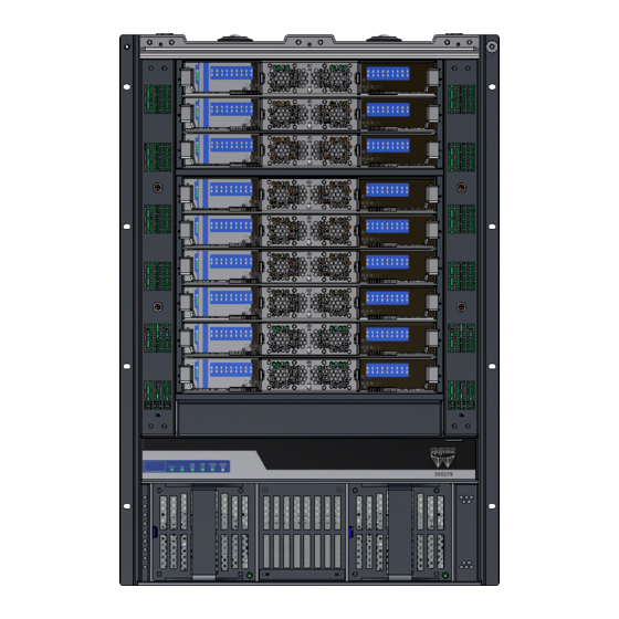
Mellanox Technologies SX6518-NR Hardware User Manual (143 pages)
324-Port Switch Platform
Brand:
Mellanox Technologies
| Category:
Switch
| Size: 4 MB
Table of Contents
Table of Contents
3
List of Figures
7
Revision History
10
Table 1: Revision History of this User's Manual
10
About this Manual
12
Intended Audience
12
Related Documentation
12
Table 2: Reference Documents and Websites
12
Mellanox Part Numbering Legend
13
Chapter 1 Overview
14
Product Information
14
Serial Number and Product Version Information
14
Figure 1: Product Label
14
Management Module MAC
15
Product Physical Specifications and Power
15
Figure 2: Product Label Tab Location
15
Figure 3: Management Module MAC Address Location
15
Figure 4: SX6518 Switch Views
16
Features List
17
Infiniband FDR and FDR10 Overview
17
Power Supply Redundancy
18
1000W Power Supply Units
18
Table 3: Opns for Power Supply Units
19
Chapter 2 Installation
20
Installation Safety Warnings
20
Installation Instructions
20
Over-Temperature
21
Equipment Installation
22
Installation Codes
22
Interconnection of Units
24
Environmental and Safety Recommendations
25
Chassis Package Contents
25
Leaf Package Contents
26
Spine Package Contents
26
Management Package Contents
26
Physical Installation
26
Starting with the Rack
27
Preparing the Rack
27
Figure 5: Distance between the Vertical Supports
27
ESD Connection
28
Installation Procedure
28
Figure 6: Installation Kit Parts
30
Figure 7: Shock Stickers
31
Opening the Container
32
Figure 8: Container Screws
32
Installing the Shelf
33
Figure 9: Vertical Rack Supports Dimension
34
Figure 10: Placement of Chassis in Rack
34
Figure 11: Adjustable Shelf Brackets
35
Figure 12: Top of Shelf Bracket
36
Figure 13: Placing the Shelf Bracket
36
Figure 14: Caged Nut Locations for the Shelf Brackets
37
Figure 15: Shelf Brackets
38
Figure 16: U Numbering above Shelf
38
Figure 17: Putting the Chassis in the Rack Using a Fork Lift
39
Figure 18: Putting the Chassis in the Rack Using a Mechanical Lift
40
Figure 19: Place the Upper Bracket Offset
40
Figure 20: Attach the Shelf Extension
41
Figure 21: Caged Nut Placement by U Numbers
42
Figure 22: Location for the Lock-Down Bar
43
Figure 23: Fork Lift
43
Figure 24: Mechanical Lift
43
Figure 25: Face Plate Mounting Bolt Locations
44
Figure 26: Upper Bracket Installation
45
Figure 27: Upper Brackets and Offset Location
45
Figure 28: Offset to Upper Bracket Bolts
46
Figure 29: Location for the Lock-Down Bar
46
Figure 30: Lock-Down Bar
46
Figure 31: Lock-Down Bars Bolt and Washer Order
47
Figure 32: Spine Side with Filler Panels
48
Installing the Cable Holder
49
Figure 33: Cable Holder
49
Ground Connections
50
Power Connections
51
Figure 34: Ground Connection
51
Connecting to an AC Power Source
52
Powering up the Switch Platform
52
Infiniband QSFP Cable Installation
53
Figure 35: Multiple Power Inlets - Electric Caution Notification
53
Figure 36: Spine Module
53
Supported Approved Cables
54
Cable Power Classes
54
Hot Swap Insertion and Extraction
55
Power Supply Units
55
Extracting and Inserting the Power Supply Unit
55
Leaf Boards
56
Figure 37: Power Cord Numbering
56
Figure 38: Power Supply
56
Figure 39: Leaf Board Numbering
57
Figure 40: Ejector Handle
57
Figure 41: Leaf Release
58
Figure 42: Intact Vs Defected Signal Connectors
58
Figure 43: Intact Vs Defected Power Pin Holders
59
Spine Boards
60
Figure 44: Management Module Numbering
61
Figure 45: Spine Board Extraction
61
Inserting a Spine Board
62
Figure 46: Intact Vs Defected Mechanics
62
Figure 47: Intact Vs Defected Side Signal Connectors
63
Figure 48: Intact Vs Defected Middle Signal Connectors
63
Figure 49: Intact Vs Defected Power Pin Holders
64
Figure 50: Spine Board Insertion Caution
64
Fan Modules
65
Figure 51: Leaf Fan Locations on the Chassis
65
Figure 52: Leaf Fan Module Extraction
66
Figure 53: Spine Fan Module
66
Figure 54: Fan Status LED on the Spine Module
67
Management Module
68
Figure 55: Management Module
68
Inserting a Management Module
69
Figure 56: Intact Vs Defected Signal Connectors
69
Figure 57: Intact Vs Defected Power Pin Holders
69
Switch Shut-Down Procedures
70
Chapter 3 Interfaces
71
LED Status Indicators
71
Power Supply Unit Leds
71
Figure 58: Power Supply Unit Status Indications
71
Leaf Board LED Indicators
72
Status LED
72
Figure 59: PSU Cover on and off
72
Figure 60: Leaf Board Led Indicators
72
Table 4: Leaf Status LED
73
Table 5: Bad Port LED Configurations
73
Table 6: Connector Physical and Logical Link Indications
73
Spine Board LED Indicators
74
Table 7: Spine Status LED
75
Table 8: Spine Fan Status LED
75
Figure 61: Spine Status Leds
75
Spine Side Panel Display LED Indicators
76
Table 9: Spine to Leaf IB Link Status
76
Table 10: Bad Port LED Configurations
76
Table 11: Spine Side LED Display for Normal Operation
77
Figure 62: Spine Side Panel Display Status Indications
77
Management Module LED Indicators
78
Table 12: Management LED Display for Normal Operation
78
Figure 63: Management Module Status Indications
78
Table 13: Management Module PSU LED Configurations
79
Table 14: Management Module S.fan LED Configurations
79
Table 15: Management Module L.fan LED Configurations
79
Figure 64: Management Module Leds
79
Port Connector Interfaces
80
Air Flow
80
QSFP Cable Power Budget Classification
80
Management Module Interfaces
80
Table 16: Management Module MASTER LED Configurations
80
Figure 65: Port Numbering
80
Figure 66: Top and Bottom Ports
80
I2C
81
Console
81
MGT- Management
81
Usb
81
Figure 67: Management Module Interfaces
81
Reset - RST
82
AC Power Interface
82
Figure 68: Reset Button
82
Chapter 4 Chassis Power up
83
Power Supply and Spine Board Indicator Status at Power on
84
Figure 69: Spine Side Panel Display Status Indications
84
Figure 70: Management Module Status Indications for Normal Operation
84
Chapter 5 Switch Management Tools
85
Infiniband Subnet Manager
86
Fabric Inspector (Diagnostics)
86
Accessing the CPU Via the Ethernet Connector
86
Upgrading and Downgrading Software
86
Figure 71: Sx65Xx Downgrade Attention Sticker
87
Chapter 6 Troubleshooting
88
Power Supply Unit
88
Leaf Board
88
Management Module
89
Spine Board
90
MLNX-OS® Software
90
Chapter 7 Disassembly and Disposal
92
Disassembling the Chassis
92
Removing the Chassis
92
Removing the Bottom Shelf
93
Figure 72: Mechanical Lifting Device
93
Disposal
94
Appendix A: Specification Data
95
Table 17: Switch Specification SX6518
95
EMI Certification
97
Approved Cables
97
EMC Certifications
97
Appendix B: Thermal Threshold Definitions
98
Appendix C: Calculating the Weight of a Customized Chassis
99
Table 18: Switch System Weight Calculation
99
Appendix D: Calculating the Power of a Chassis
100
Table 19: Power Consumption of Chassis Parts
100
Table 20: QSFP Cable Power Consumption
100
Table 21: Calculating Total Switch System Power Consumption
100
Appendix E: QSFP Interface
102
Table 22: Infiniband QSFP Connector Pinout
102
Figure 73: Infiniband QSFP Connector Symbol
103
Figure 74: QSFP Connector Male and Female Views
104
Appendix F: Replacement Parts Ordering Numbers
105
Table 23: Replacement Parts Ordering Numbers
105
Appendix G: Safety Warnings (Multiple Languages)
107
Nordic Countries Notices
107
Installation Safety Warnings (English)
107
安裝安全性警告 (Chinese)
113
Avertissements de Sécurité pour L'installation (French)
117
Instructions D'installation
117
Installation Sicherheitshinweise(German)
120
WEEE-Direktive
123
Advertencias de Seguridad de Instalación (Spanish)
123
Instrucciones de Instalación
123
Предупреждения По Технике Безопасности При Установке (Russian)
126
Avertismente Privind Siguranţa la Instalare (Romanian)
129
Instrucţiuni de Instalare
129
Sigurnosna Upozorenja Za Instaliranje (Croatian)
133
Avvertenze DI Sicurezza Per L'installazione (Italiano)
136
Istruzioni DI Installazione
136
Montaj Güvenlik Uyarıları (Türkçe)
140
Montaj Talimatları
140
Japan VCCI Class a Statement
143
Advertisement
Mellanox Technologies SX6518-NR Hardware Installation Manual (123 pages)
QSFP Chassis InfiniBand Switch Platform
Brand:
Mellanox Technologies
| Category:
Switch
| Size: 3 MB
Table of Contents
Table of Contents
3
List of Tables
5
List of Figures
6
Revision History
8
Table 1: Revision History of this Installation Guide
8
Table 2: Reference Documents and Websites
9
Mellanox Part Numbering Legend
10
About this Manual
8
Chapter 1 Installation
11
Installation Safety Warnings
11
Environmental and Safety Recommendations
15
Chassis Package Contents
16
Leaf Package Contents
17
Spine Package Contents
17
Management Package Contents
17
Physical Installation
17
Starting with the Rack
18
ESD Connection
18
Figure 1: Distance between the Vertical Supports
18
Installation Procedure
19
Figure 2: Installation Kit Parts
20
Figure 3: Shock and Tilt Stickers
21
Figure 4: Container Screws
22
Figure 5: Vertical Rack Supports Dimension
24
Figure 6: Placement of Chassis in Rack
24
Figure 7: Adjustable Shelf Brackets
25
Figure 8: Top of Shelf Bracket
25
Figure 9: Placing the Shelf Bracket
26
Figure 10: Caged Nut Locations for the Shelf Brackets
26
Figure 11: Shelf Brackets
27
Figure 12: U Numbering above Shelf
27
Figure 13: Putting the Chassis in the Rack Using a Fork Lift
28
Figure 14: Putting the Chassis in the Rack Using a Mechanical Lift
29
Figure 15: Place the Upper Bracket Offset
29
Figure 16: Attach the Shelf Extension
30
Figure 17: Caged Nut Placement by U Numbers
31
Figure 18: Location for the Lock-Down Bar
31
Figure 19: Fork Lift
32
Figure 20: Mechanical Lift
32
Figure 21: Face Plate Mounting Bolt Locations
33
Figure 22: Upper Bracket Installation
33
Figure 23: Upper Brackets and Offset Location
34
Figure 24: Offset to Upper Bracket Bolts
34
Figure 25: Location for the Lock-Down Bar
34
Figure 26: Lock-Down Bar
35
Figure 27: Lock-Down Bars Bolt and Washer Order
35
Figure 28: Spine Side with Filler Panels
36
Installing the Cable Holder
37
Figure 29: Cable Holder
37
Ground Connections
38
Power Connections
39
Powering up the Switch Platform
39
Figure 30: Ground Connection
39
Figure 31: Multiple Power Inlets - Electric Caution Notification
40
Infiniband QSFP Cable Installation
41
Figure 32: Spine Module
41
Cable Power Classes
42
Supported Approved Cables
42
Hot Swap Insertion and Extraction
42
1.10.1 Power Supply Units
43
Figure 33: Power Cord Numbering
43
Figure 34: Power Supply
43
1.10.2 Leaf Boards
44
Figure 35: Leaf Board Numbering
44
Figure 36: Ejector Handle
45
Figure 37: Leaf Release
45
Figure 38: Intact Vs Defected Signal Connectors
46
Figure 39: Intact Vs Defected Power Pin Holders
46
1.10.3 Spine Boards
47
Figure 40: Management Module Numbering
48
Figure 41: Spine Board Extraction
48
Figure 42: Intact Vs Defected Mechanics
50
Figure 43: Intact Vs Defected Side Signal Connectors
50
Figure 44: Intact Vs Defected Middle Signal Connectors
51
Figure 45: Intact Vs Defected Power Pin Holders
51
Figure 46: Spine Board Insertion Caution
51
1.10.4 Fan Modules
52
Figure 47: Leaf Fan Locations on the Chassis
53
Figure 48: Leaf Fan Module Extraction
53
Figure 49: Spine Fan Module
54
Figure 50: Fan Status LED on the Spine Module
54
1.10.5 Management Module
55
Figure 51: Management Module
55
Figure 52: Intact Vs Defected Signal Connectors
56
Figure 53: Intact Vs Defected Power Pin Holders
56
1.10.6 Switch Shut-Down Procedures
57
Chapter 2 Interfaces
58
LED Status Indicators
58
Power Supply Unit Leds
58
Figure 54: Power Supply Unit Status Indications
58
Leaf Board LED Indicators
59
Figure 55: PSU Cover on and off
59
Figure 56: Leaf Board Led Indicators
59
Table 3: Leaf Status LED
60
Table 4: Bad Port LED Configurations
60
Table 5: Connector Physical and Logical Link Indications
60
Spine Board LED Indicators
61
Table 6: Spine Status LED
62
Table 7: Spine Fan Status LED
62
Figure 57: Spine Status Leds
62
Spine Side Panel Display LED Indicators
63
Table 8: Spine to Leaf IB Link Status
63
Table 9: Bad Port LED Configurations
63
Figure 58: Spine Side Panel Display Status Indications
63
Management Module LED Indicators
64
Table 10: Leds Display for Normal Operation
64
Figure 59: Management Module Status Indications
64
Table 11: Leds Display for Normal Operation
65
Table 12: Management Module PSU LED Configurations
65
Figure 60: Management Module Leds
65
Port Connector Interfaces
66
Table 13: Management Module S.fan LED Configurations
66
Table 14: Management Module L.fan LED Configurations
66
Table 15: Management Module MASTER LED Configurations
66
Figure 61: Port Numbering
66
Figure 62: Top and Bottom Ports
66
Air Flow
67
QSFP Cable Power Budget Classification
67
Management Module Interfaces
67
I2C
67
Console
67
MGT- Management
67
Figure 63: Management Module Interfaces
67
Figure 64: Reset Button
68
Reset - RST
68
Usb
68
Chapter 3 Chassis Power up
69
Power Supply and Spine Board Indicator Status at Power on
70
Figure 65: Spine Side Panel Display Status Indications
70
Figure 66: Management Module Status Indications for Normal Operation
70
Chapter 4 First-Time Configuration
71
Running the Wizard
71
Figure 67: Console Ports for Sx60Xx/Sx65Xx Managed Systems
71
Table 16: Serial Terminal Program Configuration
72
Table 17: Configuration Wizard Session - IP Configuration by DHCP
72
Table 18: Configuration Wizard Session - IP Zeroconf Configuration
74
Table 19: Configuration Wizard Session - Static IP Configuration
75
Re-Running the Wizard
76
Starting the Command Line (CLI)
76
Starting the Web User Interface
77
Figure 68: MLNX-OS Login Window
77
Figure 69: EULA Prompt
78
Figure 70: Display after Login
78
Chapter 5 Resetting the Switch - RST
79
Figure 71: Reset Button
79
Chapter 6 Troubleshooting
80
Power Supply Unit
80
Leaf Board
80
Management Module
81
Spine Board
82
MLNX-OS® Software
82
Chapter 7 Disassembly and Disposal
84
Disassembling the Chassis
84
Removing the Chassis
84
Removing the Bottom Shelf
85
Disposal
85
Figure 72: Mechanical Lifting Device
85
Appendix A Installation Safety Warnings
86
Installation Safety Warnings (English)
86
安裝安全性警告 (Chinese)
90
Avertissements de Sécurité Pour L'installation (French)
95
Installation Sicherheitshinweise(German)
100
A.4 Installation Sicherheitshinweise(German)
100
Advertencias de Seguridad de Instalación (Spanish)
104
Предупреждения По Технике Безопасности При Установке (Russian)
108
Avertismente Privind Siguranţa la Instalare (Romanian)
112
Sigurnosna Upozorenja Za Instaliranje (Croatian)
117
Advertisement
Related Products
Mellanox Technologies SX6518-6R
Mellanox Technologies SX6518
Mellanox Technologies SX67X0
Mellanox Technologies SX6710
Mellanox Technologies SX6720
Mellanox Technologies SX6710G
Mellanox Technologies SX6730
Mellanox Technologies SX6790
Mellanox Technologies SX6036
Mellanox Technologies Mellanox SX1018
Mellanox Technologies Categories
Switch
Computer Hardware
Adapter
Network Card
Network Router
More Mellanox Technologies Manuals
Login
Sign In
OR
Sign in with Facebook
Sign in with Google
Upload manual
Upload from disk
Upload from URL