Table of Contents
Advertisement
Quick Links
Advertisement
Table of Contents

Related Manuals for Pepperl+Fuchs VB14N


Summary of Contents for Pepperl+Fuchs VB14N
- Page 1 FACTORY AUTOMATION MANUAL VB14N BARCODESCANNER...
- Page 2 VB14N With regard to the supply of products, the current issue of the following document is ap- plicable: The General Terms of Delivery for Products and Services of the Electrical In- dustry, published by the Central Association of the Electrical Industry (Zentralverband Elektrotechnik und Elektroindustrie (ZVEI) e.V.) in its most recent version as well as the...
-
Page 3: Table Of Contents
How To Setup/Configure the Scanner Network ................18 Human Machine Interface ......................19 2.3.1 Diagnostic Indication........................19 2.3.2 Mode Button Functions......................20 INSTALLATION ........................22 Mechanical Installation ......................22 3.1.1 Mounting VB14N........................23 3.1.2 Mounting Scanner Accessories ....................24 Positioning ..........................25 CBX ELECTRICAL CONNECTIONS..................27 Power Supply..........................28 Main Serial Interface........................28 4.2.1 RS232 Interface.........................29 4.2.2... - Page 4 VB14N 5.2.2 RS485 Full-Duplex Interface .....................47 5.2.3 RS485 Half-Duplex Interface.....................48 ID-NET™ Interface ........................49 5.3.1 ID-NET™ Cables ........................49 5.3.2 ID-NET™ Response Time ......................50 5.3.3 ID-NET™ Network Termination....................54 Auxiliary RS232 Interface ......................54 Inputs ............................55 5.5.1 Code Verifier..........................58 Outputs ............................58 User Interface - Host........................59 TYPICAL LAYOUTS .........................60...
-
Page 5: References
“Device” refers to the VB14N. “You” refers to the System Administrator or Technical Support person using this manual to install, mount, operate, maintain or troubleshoot a VB14N. REFERENCE DOCUMENTATION The documentation related to the VB14N management is listed below: CBX100 Installation Manual ... -
Page 6: Safety And Compliance Notices
LASER SAFETY The following information is provided to comply with the rules imposed by international authorities and refers to the correct use of the VB14N scanner. Standard Regulations This scanner utilizes a low-power laser diode. Although staring directly at the laser beam momentarily causes no known biological damage, avoid staring at the beam as one would with any very strong light source, such as the sun. -
Page 7: Fcc Compliance
Warning and Device Class Labels FCC COMPLIANCE Modifications or changes to this equipment without the expressed written approval of Pepperl+Fuchs could void the authority to use the equipment. This device complies with PART 15 of the FCC Rules. Operation is subject to the following two conditions: (1) This device may not cause harmful interference, and (2) this device must accept any interference received, including interference which may cause undesired operation. -
Page 8: Handling
VB14N HANDLING The VB14N is designed to be used in an industrial environment and is built to withstand vibration and shock when correctly installed, however it is also a precision product and therefore before and during installation it must be handled correctly to avoid damage. - Page 9 VB14N do not weld the scanner into position which can cause electrostatic, heat or output window damage. do not spray paint near the scanner which can cause output window damage.
-
Page 10: General View
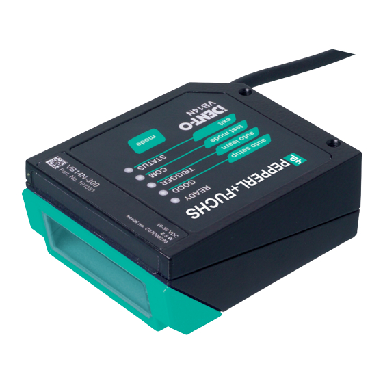
VB14N GENERAL VIEW VB14N Figure A Laser Beam Output Window Warning and Device Class Labels "COM" LED "POWER ON" LED "STATUS" LED Mounting Holes "READY" LED Push Button "GOOD" LED Accessory Mounting Holes "TRIGGER" LED... -
Page 11: Rapid Configuration
When On-Line Operating mode is used, the scanner is activated by an External Trigger (photoelectric sensor) when the object enters its reading zone. 24V DC MAIN VB14N CBX100/500 Host * Presence Sensor I/O, AUX P.S. (for On-Line mode) Figure 1 – VB14N in Stand Alone Layout... - Page 12 VB14N CBX100/500 Pinout for VB14N The table below gives the pinout of the CBX100/500 terminal block connectors. Use this pinout when the VB14N reader is connected by means of the CBX100/500: CBX100/500 Terminal Block Connectors Input Power Outputs Power Supply Input Voltage +...
- Page 13 25-pin Connector Pinout for VB14N The table below gives the pinout of the 25-pin male D-sub connector for connection to the power supply and input/output signals. Use this pinout when the VB14N reader is connected by means of the 25-pin connector:...
-
Page 14: Step 2 - Mounting And Positioning The System
VB14N STEP 2 – MOUNTING AND POSITIONING THE SYSTEM 1. To mount the VB14N, use the mounting bracket to obtain the most suitable position for the reader as shown in the figures below. Skew Tilt Pitch Skew Figure 3 - Positioning with Mounting Bracket 2. -
Page 15: Step 3 - Mode Button Configuration
VB14N STEP 3 – MODE BUTTON CONFIGURATION The Mode Button is the intuitive Human Machine Interface designed to improve ease of installation and maintenance. Status and diagnostic information are clearly presented by means of the five colored LEDs, whereas the single push button gives immediate access to the following relevant functions: ... -
Page 16: Auto Learn
VB14N Auto Learn If you are configuring your scanner using the Mode Button, you must start with the Auto Learn procedure. 1. Enter the Auto Learn function by holding the Mode push button pressed until the LEARN LED is 2. Release the button to enter the Auto Learn function. - Page 17 VB14N Auto Setup (Optional) At the end of the Auto Learn procedure, you have the possibility to follow the Auto Setup procedure to set up the reading parameters. 1. Enter the Auto Setup function by holding the Mode push button pressed until the SETUP LED is 2.
-
Page 18: Wizard For Quick Reader Setup
VB14N STEP 4 – INSTALLING GENIUS™ CONFIGURATION PROGRAM ™ Genius is a Barcode scanner configuration tool providing several important advantages: Wizard approach for new users; Multi-language version; Defined configuration directly stored in the reader; Communication protocol independent from the physical interface allowing to consider the reader as a remote object to be configured and monitored. - Page 19 VB14N 1. Select the Create a new configuration button. You will be guided through the configuration being asked to define the following parameters: Barcode selection and definition...
- Page 20 VB14N Operating mode selection and definition Digital Outputs configuration...
- Page 21 VB14N Hardware interface selection Output data format configuration The On Line operating Mode requires the reader to be connected to an External Trigger/Presence Sensor using I1A and I1B inputs. The Automatic operating mode does not require connection to an external Presence Sensor.
- Page 22 VB14N 2. After defining the parameter values the following window appears allowing to complete the reader configuration as follows: Saving the configuration to disk; Switching to Advanced mode; Sending the configuration to the scanner. 3. After sending the configuration to the 4.
-
Page 23: Step 5 - Test Mode
VB14N STEP 5 – TEST MODE Use a code suitable to your application to test the system. 1. Enter the Test mode function by holding the Mode push button pressed until the TEST LED is on. 2. Release the button to enter the Test mode function. -
Page 24: Advanced Scanner Configuration
If you need to install a Pass-Through network refer to the VB14N Reference Manual. If you need to install a Multiplexer network refer to the VB14N Reference Manual. If you need to install an RS232 Master/Slave (for backward compatibility) refer to the VB14N Reference Manual. -
Page 25: Introduction
2 INTRODUCTION 2.1 PRODUCT DESCRIPTION The VB14N laser scanner satisfies the most advanced needs of a wide range of users. It has been developed focusing on the realistic requirements of its target market. The outstanding result is an extremely compact, cost-effective and easy to use industrial scanner. -
Page 26: Indicators
VB14N 2.1.1 Indicators Figure A The five LEDs on the side of the scanner ( ) indicate the following: This LED indicates the device is ready to operate. READY (green) This LED confirms successful reading. GOOD (green) This LED indicates the status of the reading phase. *... - Page 27 VB14N ID-NET™ M/S Multidata: Multiple stations – single scanner CBX100 CBX100 CBX100 ID-NET™ interface allows connection of scanners reading objects placed on independent conveyors. All scanners are typically located far away from each other and they use a dedicated presence sensor.
-
Page 28: How To Setup/Configure The Scanner Network
VB14N 2.2.1 How To Setup/Configure the Scanner Network A complete ID-NET™ scanner network can be rapidly setup, as follows: Mounting & Connection 1. Mechanically mount/install all the readers (refer to par. 3.1 and 3.2). 2. Wire ID-NET™ (refer to par. 4.3 or 5.3). -
Page 29: Human Machine Interface
VB14N 2.3 HUMAN MACHINE INTERFACE The Mode Button is the intuitive Human Machine Interface designed with the precise goal of improving ease of installation and maintenance. Status and diagnostic information are clearly presented by means of five-colored LEDs, whereas the single multi-function key gives immediate access to relevant functions: ... -
Page 30: Mode Button Functions
VB14N 2.3.2 Mode Button Functions Quick access to the following functions is provided by an easy procedure using the push button: 1 – Press the button (the STATUS LED will give a visual feedback). 2 – Hold the button until the specific function LED is on (TEST, LEARN or SETUP). - Page 31 VB14N AutoLearn Function Once entered, the reader starts a procedure to automatically detect and recognize barcodes (by type and length), which are presented to it . The laser turns on and the LEARN LED blinks to indicate the ongoing process.
-
Page 32: Installation
VB14N 3 INSTALLATION 3.1 MECHANICAL INSTALLATION VB14N can be installed to operate in different positions. The four screw holes (M4 x 5) on the body of Figure A the reader are for mechanical fixture ( , 3). The diagrams below give the overall dimensions of the scanner and mounting bracket and may be used for installation. -
Page 33: Mounting Vb14N
VB14N 3.1.1 Mounting VB14N Using the VB14N mounting bracket you can obtain the most suitable position for the reader as shown in the figure below: Tilt Skew Skew Pitch Figure 13 – Positioning with Mounting Bracket... -
Page 34: Mounting Scanner Accessories
2. Remove the VB14N scanning window unscrewing the two cover screws. 3. Fix the mirror to the device by means of the two fixing screws. 4. Remount the scanning window so that the opening face is now at 90° with respect to the VB14N body. -
Page 35: Positioning
The Skew angle is represented by the value S in Figure 15. Position the reader to assure at least 10° for the Skew angle. This avoids the direct reflection of the laser light emitted by the VB14N. For the raster version, this angle refers to the most inclined or external raster line, so that all other raster lines assure more than 10°... - Page 36 VB14N The Pitch angle is represented by the value P in Figure 17. Position the reader in order to minimize the Pitch angle. Figure 17 - Pitch Angle...
-
Page 37: Cbx Electrical Connections
VB14N 4 CBX ELECTRICAL CONNECTIONS All VB14N models are equipped with a cable terminated by a 25-pin male D-sub connector for connection to the power supply and input/output signals. We recommend making system connections through one of the CBX connection boxes since they offer the advantages of easy connection, easy device replacement and filtered reference signals. -
Page 38: Power Supply
VB14N To avoid electromagnetic interference when the scanner is connected to a CBX connection box, verify the jumper positions in the CBX as indicated in its Installation Manual. NOTE 4.1 POWER SUPPLY Power can be supplied to the scanner through the CBX100/500 spring clamp terminal pins as shown... -
Page 39: Rs232 Interface
IDLE IDLE Figure 20 - RS232 Control Signals If the RTS/CTS handshaking protocol is enabled, the VB14N activates the RTS output to indicate a message is to be transmitted. The receiving unit activates the CTS input to enable the transmission. -
Page 40: Rs485 Full-Duplex Interface
VB14N 4.2.2 RS485 Full-Duplex Interface The RS485 full-duplex (5 wires + shield) interface is used for non-polled communication protocols in point-to-point connections over longer distances (max 1200 m / 3940 ft) than those acceptable for RS232 communications or in electrically noisy environments. -
Page 41: Rs485 Half-Duplex Interface
VB14N 4.2.3 RS485 Half-Duplex Interface This interface is provided for backward compatibility. We recommend using the more efficient ID-NET™ network for Master/Slave or Multiplexer layouts. NOTE The RS485 half-duplex (3 wires + shield) interface is used for polled communication protocols. -
Page 42: Id-Net™ Interface
VB14N 4.3 ID-NET™ INTERFACE CBX100/500 Function Shield Network Cable Shield ID-NET™ network + ID-NET™ network - Network Reference 4.3.1 ID-NET™ Cables The following instructions are referred to Figure 25, Figure 26 and Figure 27. The general cable type specifications are: CAT5 twisted pair + additional CAT5 twisted pair, shielded cable AWG 24 (or AWG 22) stranded flexible. -
Page 43: Id-Net™ Response Time
VB14N 4.3.2 ID-NET™ Response Time The following figure shows the response time of the ID-NET™ network. This time is defined as the period between the Trigger activation and the beginning of data transmission to the Host. Max ID-NET™ Response Time... - Page 44 VB14N 24V DC 24V DC 24V DC Figure 25 – ID-NET™ Network Connections with isolated power blocks...
- Page 45 VB14N Figure 26 - ID-NET™ Network Connections with Common Power Branch Network...
- Page 46 VB14N Figure 27 – ID-NET™ Network Connections with Common Power Star Network...
-
Page 47: Id-Net™ Network Termination
VB14N 4.3.3 ID-NET™ Network Termination The network must be properly terminated in the first and last scanner of the network. This is done by setting the ID-NET™ Termination Resistance Switch in the CBX100/500 to ON. 4.4 AUXILIARY RS232 INTERFACE The auxiliary serial interface is used exclusively for RS232 point-to-point connections. -
Page 48: Inputs
EXTERNAL TRIGGER INPUT CONNECTIONS USING VB14N POWER Trigger sensor (PNP) (bro wn) (b lack) (blue) Figure 30 – Trigger sensor (PNP) External Trigger Using VB14N Power NPN sensor Power to Input Phot oc ell Signal... - Page 49 VB14N PNP Photocell Input Signal Pulled down to External Input Device Reference Figure 32 - PNP External Trigger Using External Power NPN Photocell Pulled up to External Input Device Power Input Signal Figure 33 - NPN External Trigger Using External Power...
- Page 50 VB14N CBX100/500 Function Power Source - Inputs Input 2 A (polarity insensitive) Input 2 B (polarity insensitive) Power Reference - Inputs INPUT 2 CONNECTIONS USING VB14N POWER Input Device Power to Input Device Input Input Device Signal Reference PNP Input 2 Using VB14N Power...
-
Page 51: Code Verifier
VB14N 4.5.1 Code Verifier If the VB14N is used as a Code Verifier, the verifier code can be configured in software through the Genius™ configuration program. However it is also possible to use one of the inputs to trigger when the scanner should store a code read as the verifier code. - Page 52 OUTPUT CONNECTIONS USING VB14N POWER Output Device Power to Output Output device Signal Output device Reference Figure 36 - Open Emitter Output Using VB14N Power Output Device Power to Output device Output device Reference Output Signal Figure 37 - Open Collector Output Using VB14N Power...
-
Page 53: User Interface - Host
VB14N 4.7 USER INTERFACE - HOST The following table contains the pinout for standard RS232 PC Host interface. For other user interface types please refer to their own manual. RS232 PC-side connections 9-pin male connector 25-pin male connector Name Name... -
Page 54: 25-Pin Cable Electrical Connections
VB14N 5 25-PIN CABLE ELECTRICAL CONNECTIONS All VB14N models are equipped with a cable terminated by a 25-pin male D-sub connector for connection to the power supply and input/output signals. The details of the connector pins are indicated in the following table. -
Page 55: Power Supply
VB14N 5.1 POWER SUPPLY Power can be supplied to the scanner through the pins provided on the 25-pin connector used for communication with the host (Figure 41): POWER SUPPLY VB14N V+ (10 - 30 Vdc) VGND CHASSIS CHASSIS Earth Ground Figure 41 - Power Supply Connections The power must be between 10 and 30 Vdc only. -
Page 56: Rs232 Interface
IDLE IDLE Figure 43 - RS232 Control Signals If the RTS/CTS handshaking protocol is enabled, the VB14N activates the RTS output to indicate a message is to be transmitted. The receiving unit activates the CTS input to enable the transmission. -
Page 57: Rs485 Full-Duplex Interface
VB14N 5.2.2 RS485 Full-Duplex Interface The RS485 full-duplex (5 wires + shield) interface is used for non-polled communication protocols in point-to-point connections over longer distances (max 1200 m / 3940 ft) than those acceptable for RS232 communications or in electrically noisy environments. -
Page 58: Rs485 Half-Duplex Interface
VB14N 5.2.3 RS485 Half-Duplex Interface This interface is provided for backward compatibility. We recommend using the more efficient ID-NET™ network for Master/Slave or Multiplexer layouts. NOTE The RS485 half-duplex (3 wires + shield) interface is used for polled communication protocols. -
Page 59: Id-Net™ Interface
VB14N 5.3 ID-NET™ INTERFACE 25-pin Name Function ID-NET™ network + ID-NET™ network - Ground 5.3.1 ID-NET™ Cables The following instructions are referred to Figure 48, Figure 49 and Figure 50. The general cable type specifications are: CAT5 twisted pair + additional CAT5 twisted pair, shielded cable AWG 24 (or AWG 22) stranded flexible. -
Page 60: Id-Net™ Response Time
VB14N 5.3.2 ID-NET™ Response Time The following figure shows the response time of the ID-NET™ network. This time is defined as the period between the Trigger activation and the beginning of data transmission to the Host. Max ID-NET™ Response Time... - Page 61 VB14N 24V DC 24V DC 24V DC Figure 48 – ID-NET™ Network Connections with isolated power blocks...
- Page 62 VB14N Figure 49 - ID-NET™ Network Connections with Common Power Branch Network...
- Page 63 VB14N Figure 50 – ID-NET™ Network Connections with Common Power Star Network...
-
Page 64: Id-Net™ Network Termination
VB14N 5.3.3 ID-NET™ Network Termination The network must be properly terminated by a 120 Ohm resistor at the first and last scanner of the network. 5.4 AUXILIARY RS232 INTERFACE The auxiliary serial interface is used exclusively for RS232 point-to-point connections. -
Page 65: Inputs
This input is optocoupled and can be driven by both an NPN and PNP type command. The connections are indicated in the following diagrams: EXTERNAL TRIGGER INPUT PNP Photocell VB14N PNP Photocell (brown) +10-30 Vdc (black) NO (blue) 0 V Figure 52 - Photocell (PNP) External Trigger Using VB14N Power... - Page 66 VB14N EXTERNAL TRIGGER INPUT CONNECTIONS USING VB14N POWER VB14N EXTERNAL TRIGGER Signal Ground Figure 53 - PNP External Trigger Using VB14N Power VB14N EXTERNAL TRIGGER Signal Ground Figure 54 - NPN External Trigger using VB14N Power EXTERNAL TRIGGER INPUT CONNECTIONS USING EXTERNAL POWER Vext 30 Vdc max.
- Page 67 Power Reference - Inputs INPUT 2 CONNECTIONS USING VB14N POWER VB14N INPUT DEVICE Signal Ground Figure 57 - PNP Input 2 Using VB14N Power VB14N INPUT DEVICE Signal Ground Figure 58 - NPN Input 2 Using VB14N Power INPUT 2 CONNECTIONS USING EXTERNAL POWER Vext 30 Vdc max.
-
Page 68: Code Verifier
VB14N 5.5.1 Code Verifier If the VB14N is used as a Code Verifier, the verifier code can be configured in software through the Genius™ configuration program. However it is also possible to use one of the inputs to trigger when the scanner should store a code read as the verifier code. -
Page 69: User Interface - Host
The following wiring diagram shows a simple test cable including power, external (push-button) trigger and PC RS232 COM port connections. 25-pin D-sub male 9-pin D-sub female GN D VB14N GN D Power Supply Vdc (10 – 30 Vdc) Power GND Trigger Test Cable for VB14N... -
Page 70: Typical Layouts
VB14N 6 TYPICAL LAYOUTS The following typical layouts refer to system hardware configurations. Dotted lines in the figures refer to optional hardware configurations within the particular layout. These layouts also require the correct setup of the software configuration parameters. Complete software configuration procedures can be found in the Guide To Rapid Configuration in the Genius™... - Page 71 VB14N In this layout a single scanner functions as a Slave node on a Fieldbus network. The data is transmitted to the Host through an accessory Fieldbus interface board installed inside the CBX500 connection box. Scanner configuration can be accomplished through the Auxiliary interface using the Genius™...
-
Page 72: Pass-Through
Pass-through mode allows two or more devices to be connected to a single external serial interface. Each VB14N transmits the messages received by the Auxiliary interface onto the Main interface. All messages will be passed through this chain to the host. - Page 73 Slaves) to accept input on the Auxiliary interface, for example to connect a device such as a hand-held reader for manual code reading capability. Each VB14N transmits its own messages plus any messages received by its Auxiliary interface onto the ID-NET™ interface. The Master passes all messages to the Host.
-
Page 74: Id-Net
VB14N 6.3 ID-NET™ The ID-NET™ connection is used to collect data from several scanners to build a multi-point or a multi-sided reading system; there can be one master and up to 31 slaves connected together. The slave scanners are connected together using the ID-NET™ interface. Every slave scanner must have a ID-NET™... - Page 75 VB14N For a Master/Slave Multidata layout each scanner has its own reading phase independent from the others; each single message is sent from the master scanner to the Host computer. Master Slave#1 Slave#n Terminal Power Host Main Serial Interface (RS232 or RS485) ...
- Page 76 VB14N Alternatively, the Master scanner can communicate to the Host as a Slave node on a Fieldbus network. This requires using an accessory Fieldbus interface board installed inside the CBX500 connection box. System configuration can be accomplished through the Auxiliary interface of the Master scanner (internal CBX500 9-pin connector) using the Genius™...
-
Page 77: Rs232 Master/Slave
9 slaves connected together. The Slave scanners use RS232 only on the main and auxiliary serial interfaces. Each slave VB14N transmits the messages received by the auxiliary interface onto the main interface. All messages will be passed through this chain to the Master. -
Page 78: Reading Features
VB14N 7 READING FEATURES 7.1 ADVANCED CODE BUILDER (ACB) In addition to linear reading, the Advanced Code Builder (ACB) allows code reading by “stitching” together two partial reads of it. ACB is not as powerful as Advanced Code Reconstruction due to limits on tilt angle, speed and Multi-label function;... -
Page 79: Important Acb Reading Conditions
0.125 7° 11° 7.2 LINEAR CODE READING The number of scans performed on the code by the VB14N and therefore the decoding capability is influenced by the following parameters: number of scans per second code motion speed label dimensions ... -
Page 80: Step-Ladder Mode
Direction of code movement at LS speed VB14N Laser beam Figure 72 - "Step-Ladder" Scanning Mode For example, the VB14N-300 (500 scans/sec.) for a 25 mm high code moving at 1000 mm/s performs: [(25/1000) * 500] - 2 = 10 effective scans. -
Page 81: Picket-Fence Mode
For example, for a 60 mm wide code moving in a point where the reading field is 160 mm wide at a 1500 mm/s speed, the VB14N-300 (500 scans per sec.), performs: [((160-60)/1500) * 500] - 2 = 31 effective scans... -
Page 82: Performance
Version Reading Distance VB14N-300 /-R 40 mm (1.6 in) - 300 mm (11.8 in) on 0.50 mm (20 mils) codes VB14N-600 /-R 190 mm (7.5 in) - 600 mm (23,6 in) on 0.50 mm (20 mils) codes Refer to the diagrams given in par. 7.4 for further details on the reading features. They are taken on various resolution sample codes at a 25 C ambient temperature, depending on the conditions in the... -
Page 83: Reading Diagrams
VB14N 7.4 READING DIAGRAMS VB14N-300 /-R NOTE: (0,0) is the center of the laser beam output window. CONDITIONS Optic Version Linear Code Interleaved 2/5 or Code 39 0.90 "Pitch" angle 0 "Skew" angle 15 "Tilt" angle 0 *Reading Conditions Standard... - Page 84 VB14N VB14N-600 /-R NOTE: (0,0) is the center of the laser beam output window. CONDITIONS Optic Version Linear Code Interleaved 2/5 or Code 39 0.90 "Pitch" angle 0 "Skew" angle 10 "Tilt" angle 0 *Code Resolution High for 0.35mm (14 mils) codes Standard for 0.50mm (20 mils) codes or greater...
- Page 85 VB14N VB14N-300 /-R Reading Distance vs Scanning Speed Distance (in) (mm) 80 100 120 140 160 180 200 220 240 260 0.50 mm 0.35 mm 0.30 mm 0.20 mm 500 scans/s Code 800 scans/s Resolution...
-
Page 86: Maintenance
Repeat the operation frequently in particularly dirty environments. Use soft material and alcohol to clean the window and avoid any abrasive substances. Clean the window of the VB14N when the scanner is turned off or, at least, when the laser beam is deactivated. -
Page 87: Troubleshooting
VB14N 9 TROUBLESHOOTING 9.1 GENERAL GUIDELINES When wiring the device, pay careful attention to the signal name (acronym) on the CBX100/500 spring clamp connectors (chp. 4). If you are connecting directly to the scanner 25-pin connector pay attention to the pin number of the signals (chp 5). - Page 88 VB14N TROUBLESHOOTING GUIDE Problem Suggestions Reading: Check synchronization of reading pulse with object to read: Not possible to read the Is the scan line correctly positioned? target barcode (always Place barcode in the center of scan line and run Test mode (selectable returns No Read) or the by Genius™...
-
Page 89: Technical Features
VB14N 10 TECHNICAL FEATURES ELECTRICAL FEATURES VB14N-300 /-R VB14N-600 /-R Input Power Supply Voltage 10 to 30 Vdc Power consumption max. 0.3 to 0.1 A; 3 W 0.5 to 0.17 A; 5 W Serial Interfaces Main Serial Interface Sw programmable: RS232; RS485 FD and HD... - Page 90 VB14N SOFTWARE FEATURES READABLE CODES * EAN/UPC (including Add-on 2 and Add-on 5) * Code 93 * 2/5 Interleaved * Code 128 * Code 39 (Standard and Full ASCII) * EAN 128 * Codabar ISBT 128 *ABC Codabar Pharmacode Plessey *ACB Readable.
-
Page 91: Glossary
VB14N GLOSSARY ACB (Advanced Code Builder) Advanced Code Builder (ACB) allows code reading by “stitching” together two partial reads of it. ACB is effective in reading codes positioned close-to-linear, small height codes, damaged codes, or poor print quality codes. See par. 7.1. - Page 92 VB14N Host A computer that serves other terminals in a network, providing services such as network control, database access, special programs, supervisory programs, or programming languages. Interface A shared boundary defined by common physical interconnection characteristics, signal characteristics and meanings of interchanged signals.
- Page 93 VB14N Signal An impulse or fluctuating electrical quantity (i.e.: a voltage or current) the variations of which represent changes in information. Skew Rotation about the Y-axis. Rotational deviation from correct horizontal and vertical orientation; may apply to single character, line or entire encoded item. See pars. 3.1.1 and 3.2.
- Page 94 VB14N...
- Page 95 VB14N...
- Page 96 Twinsburg, Ohio 44087 · USA Tel. +1 330 4253555 E-mail: sales@us.pepperl-fuchs.com Asia Pacific Headquarters Pepperl+Fuchs Pte Ltd. Company Registration No. 199003130E Singapore 139942 Tel. +65 67799091 E-mail: sales@sg.pepperl-fuchs.com www.pepperl-fuchs.com 2190 / TDOCT1805__ENG Subject to modifications 05/2009 Copyright PEPPERL+FUCHS • Printed in Germany...
Need help?
Do you have a question about the VB14N and is the answer not in the manual?
Questions and answers