ICP DAS USA tGW-700 Series User Manual
Tiny modbus/tcp to rtu/ascii gateway
Hide thumbs
Also See for tGW-700 Series:
- User manual (61 pages) ,
- User manual (109 pages) ,
- User manual (87 pages)
Table of Contents
Advertisement
Quick Links
tGW-700 Series
User Manual
Tiny Modbus/TCP to RTU/ASCII Gateway
Warranty
All products manufactured by ICP DAS are warranted against defective materials for a period of
one year from the date of delivery to the original purchaser.
Warning
ICP DAS assumes no liability for damages consequent to the use of this product. ICP DAS
reserves the right to change this manual at any time without notice. The information furnished
by ICP DAS is believed to be accurate and reliable. However, no responsibility is assumed by
ICP DAS for its use, nor for any infringements of patents or other rights of third parties resulting
from its use.
Copyright
Copyright © 2013 by ICP DAS. All rights are reserved.
Trademark
Names are used for identification only and may be registered trademarks of their respective
companies.
-
tGW-700 Series User Manual, Version 1.7, Mar 2013
1 -
Advertisement
Table of Contents

Related Manuals for ICP DAS USA tGW-700 Series


Summary of Contents for ICP DAS USA tGW-700 Series
-
Page 1: User Manual
The information furnished by ICP DAS is believed to be accurate and reliable. However, no responsibility is assumed by ICP DAS for its use, nor for any infringements of patents or other rights of third parties resulting from its use. -
Page 2: Table Of Contents
ESTING YOUR T 4. WEB CONFIGURATION ..............................33 GW-700 W OGGING IN TO THE T EB SERVER ......................33 ................................... 35 ETWORK ETTING ..............................36 4.3.1 Network and Miscellaneous Settings ....................... 36 tGW-700 Series User Manual, Version 1.7, Mar 2013... - Page 3 ? ..............70 HY CANNOT COMPUTER PING OR SEARCH THE T SERIES MODULE 5. H GW-712 PLC? ....................71 OW TO WIRE A WIRE T WITH A WIRE APPENDIX: EXCEPTION CODES ............................72 tGW-700 Series User Manual, Version 1.7, Mar 2013...
-
Page 4: Packing List
Note!! If any of these items are missing or damaged, please contact the local distributor for more information. Save the shipping materials and cartons in case you want to ship the module in the future. More Information Documentation CD:\NAPDOS\tGW-700\Document http://ftp.icpdas.com/pub/cd/tinymodules/napdos/tgw-700/document/ Firmware CD:\NAPDOS\tGW-700\Firmware http://ftp.icpdas.com/pub/cd/tinymodules/napdos/tgw-700/firmware/ Software CD:\NAPDOS\Software http://ftp.icpdas.com/pub/cd/tinymodules/napdos/software/ tGW-700 Series User Manual, Version 1.7, Mar 2013... -
Page 5: Introduction
TCP/IP between two serial Modbus RTU/ASCII devices, which useful when connecting mainframe computers, servers or other serial devices that use Modbus RTU/ASCII protocols and do not themselves have Ethernet capability. tGW-700 Series User Manual, Version 1.7, Mar 2013... - Page 6 Comparison Table of Device Servers: Series PPDS Features Virtual COM Programmable Modbus Gateway Multi-client about 20 Sockets 4 Sockets/port Isolation for Cost-effective, Cost-effective, Remarks Professional Powerful DS-715 Entry-level Entry-level tGW-700 Series User Manual, Version 1.7, Mar 2013...
-
Page 7: Ethernet Solutions
UPS, etc. An Ethernet network can link office automation and industrial control networks, access remote systems and share data and information between multivendor machines, and it also provides a cost-effective solution for industrial control networks. tGW-700 Series User Manual, Version 1.7, Mar 2013... -
Page 8: Web Server Technology
Internet Explorer, Firefox or Mozilla, etc. This means that it is easy to check the configuration of the tGW-700 via an Ethernet network without needing to install any other software tools, thereby reducing the user’s learning curve. tGW-700 Series User Manual, Version 1.7, Mar 2013... -
Page 9: Hardware Information
DB-9 x1 Installation DIN-Rail mounting Flammability Fire Retardant Materials (UL94-V0 Level) Operating -25° ~ 75°C Temperature Storage -30° ~ 80°C Temperature Humidity 10 ~ 90% RH, non-condensing Note: COM1/COM2/COM3 = TCP port 502/503/504 tGW-700 Series User Manual, Version 1.7, Mar 2013... -
Page 10: Features
3-wire RS-232 3-Wire RS-232: RxD, TxD, GND (Non-isolated) 5-Wire RS-232: RxD, TxD, CTS, RTS, GND (No-isolated) 2-Wire RS-485: DATA+, DATA-, GND (Non-isolated) 4-Wire RS-422: TxD+, TxD-, RxD+, RxD-, GND (Non-islated) tGW-700 Series User Manual, Version 1.7, Mar 2013 10 -... -
Page 11: Tgw-700 Front View
When an Ethernet link is detected and an Ethernet packet is received, the Link/Act LED (Orange) indicator will be illuminated. When power is supplied via PoE (Power-over-Ethernet), the PoE LED (Green) indicator will be illuminated. tGW-700 Series User Manual, Version 1.7, Mar 2013 11 -... - Page 12 Init Mode: Configuration mode Run Mode: Firmware operation mode In the tGW-700 series, the operating mode Switch is in the Run position by default. When updating the tGW-700 firmware, the switch needs to be moved from the Run position to the Init position.
-
Page 13: Dimensions
Dimensions tGW-712 Dimensions: Units: mm Front View Rear View Top View Left Side View Right Side View Bottom View tGW-700 Series User Manual, Version 1.7, Mar 2013 13 -... - Page 14 tGW-722/732/715/725/735/718/724/734 Dimensions: Units: mm Front View Rear View Top View Left Side View Bottom View Right Side View tGW-700 Series User Manual, Version 1.7, Mar 2013 14 -...
-
Page 15: Pin Assignments
Pin Assignments 2.6.1 tGW-712 Pin Assignments 1-Port 5-wire RS-232 Module Note: The CTS/RTS pins are reserved (no function). tGW-700 Series User Manual, Version 1.7, Mar 2013 15 -... -
Page 16: Tgw-722 Pin Assignments
2.6.2 tGW-722 Pin Assignments 2-Port 5-wire RS-232 Module Note: The CTS/RTS pins are reserved (no function). tGW-700 Series User Manual, Version 1.7, Mar 2013 16 -... -
Page 17: Tgw-732 Pin Assignments
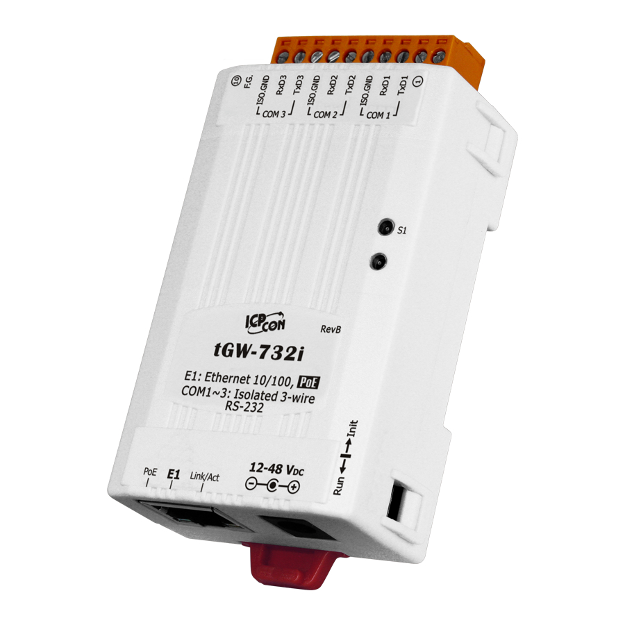
2.6.3 tGW-732 Pin Assignments 3-Port 3-wire RS-232 Module tGW-700 Series User Manual, Version 1.7, Mar 2013 17 -... -
Page 18: Tgw-715 Pin Assignments
2.6.4 tGW-715 Pin Assignments 1-Port 2-wire RS-485/4-Wire RS-422 Module tGW-700 Series User Manual, Version 1.7, Mar 2013 18 -... -
Page 19: Tgw-725 Pin Assignments
2.6.5 tGW-725 Pin Assignments 2-Port 2-wire RS-485 Module tGW-700 Series User Manual, Version 1.7, Mar 2013 19 -... -
Page 20: Tgw-735 Pin Assignments
2.6.6 tGW-735 Pin Assignments 3-Port 2-wire RS-485 Module tGW-700 Series User Manual, Version 1.7, Mar 2013 20 -... -
Page 21: Tgw-718 Pin Assignments
2.6.7 tGW-718 Pin Assignments 1-Port 3-Wire R232 and 2-Wire RS-485/4-Wire RS-422 Module tGW-700 Series User Manual, Version 1.7, Mar 2013 21 -... -
Page 22: Tgw-724 Pin Assignments
2.6.8 tGW-724 Pin Assignments 1-Port 2-Wire RS-485 and 1-Port 5-Wire RS-232 Module Note: The CTS/RTS pins are reserved (no function). tGW-700 Series User Manual, Version 1.7, Mar 2013 22 -... -
Page 23: Tgw-734 Pin Assignments
2.6.9 tGW-734 Pin Assignments 1-Port 2-Wire RS-485 and 2-Port 3-Wire R232 Module tGW-700 Series User Manual, Version 1.7, Mar 2013 23 -... -
Page 24: Wiring Notes
Wiring Notes 2.7.1 RS-232 Wiring Connections Note: FGND is the frame ground that is soldered to the DB9 metal-shield. tGW-700 Series User Manual, Version 1.7, Mar 2013 24 -... -
Page 25: Rs-422 Wiring Connections
2.7.2 RS-422 Wiring Connections 2.7.3 RS-485 Wiring Connections Note: You should connect all signal grounds of RS-422/485 devices together. This reduces the common-mode voltage between devices. tGW-700 Series User Manual, Version 1.7, Mar 2013 25 -... -
Page 26: Setting Up The Tgw-700 Module
(Contact your System Administrator for more details of how to do this) Check Init/Run switch is on Run position. Connect both the tGW-700 and your computer to the same sub-network or the same Ethernet Switch and power on the tGW-700. tGW-700 Series User Manual, Version 1.7, Mar 2013 26 -... -
Page 27: Step 2: Installing The Modbus Utility And Esearch Utility
Make sure the System LED indicator is flashing. Step 2: Installing the Modbus Utility and eSearch Utility The Modbus Utility is located at: CD: \NAPDOS\Software\Modbus_Utility http://ftp.icpdas.com/pub/cd/tinymodules/napdos/software/modbus_utility/ The eSearch Utility is located at: CD:\Napdos\software\eSearch\ http://ftp.icpdas.com/pub/cd/tinymodules/napdos/software/esearch/ tGW-700 Series User Manual, Version 1.7, Mar 2013 27 -... -
Page 28: Step 3: Search For The Tgw-700 On The Ethernet Network
3. Contact your Network Administrator to obtain the correct network configuration information such as IP/Mask/Gateway. Enter the network settings and then click “OK”. The tGW-700 will use the new settings within 2 seconds. tGW-700 Series User Manual, Version 1.7, Mar 2013 28 -... -
Page 29: Step 4: Testing Your Tgw-700
1. Wiring to the Modbus device (ex: M-7055D, optional) with your tGW-700 (RS-485 bus). For detailed RS-232/422/485 wiring information, refer to Section 2.7 Wiring Note. RS-232 Wiring: RS-485 Wiring: tGW-700 Series User Manual, Version 1.7, Mar 2013 29 -... - Page 30 4. Select the “Modbus RTU or Modbus ASCII” option from the Modbus protocol that is used by the attached Modbus devices. Note: Only one protocol can be used in a serial port. tGW-700 Series User Manual, Version 1.7, Mar 2013 30 -...
- Page 31 5. Double click the Modbus Utility shortcut on the desktop, and then click the “Modbus/TCP” button. Double Click 6. Click on the “Client tools” >> “Modbus/TCP Client”. tGW-700 Series User Manual, Version 1.7, Mar 2013 31 -...
- Page 32 (Ex: If M-7000 Modbus device ID = 1, you send “1 2 0 0 0 6 1 2 0 0 0 4” for reading D/I value, you may receive response “1 2 0 0 0 4 1 2 1 0”) Complete Type the command esponse Data tGW-700 Series User Manual, Version 1.7, Mar 2013 32 -...
-
Page 33: Web Configuration
Step 2: Type the URL address of the tGW-700 Make sure you have correctly configured the network settings for the tGW-700, or refer Section 3 Setting up the tGW-700 module. tGW-700 Series User Manual, Version 1.7, Mar 2013 33 -... - Page 34 “Submit” button to enter the configuration web page. The factory default password is: Item Default Login password admin Step 4: Welcome to tGW-700 web server After logging onto the tGW-700 web server, the main page will appear. tGW-700 Series User Manual, Version 1.7, Mar 2013 34 -...
-
Page 35: Home Page
The first part of this page provides basic information about the tGW-700 hardware and software. The second part of this page provides the status of the port settings and pair-connection settings. tGW-700 Series User Manual, Version 1.7, Mar 2013 35 -... -
Page 36: Network Setting
If the settings are changed while the module is operating, any linked connection currently in use will be lost and an error will occur. tGW-700 Series User Manual, Version 1.7, Mar 2013 36 -... - Page 37 MAC Address The user-defined MAC address. Modbus Net ID Sets the device ID of tGW-700 series module. (for Gateway) Default: 255 Update Settings Click this button to save the new settings to the tGW-700.
-
Page 38: Manual Configuration
Dynamic configuration is very easy to perform. If you have a DHCP server, the network address can be dynamically configured in the following manner: Step 1: Select “DHCP” as the address type Step 2: Click the“Update Settings” button to finish configuration tGW-700 Series User Manual, Version 1.7, Mar 2013 38 -... -
Page 39: General Configuration Settings
If there is no action for a certain period in the web server, user account will be logout. Web Auto-logout Settings range: 1 ~ 65535 (minutes); Disabled = 0; Update Settings Click this button to save the new settings to the tGW-700. tGW-700 Series User Manual, Version 1.7, Mar 2013 39 -... -
Page 40: Restore Factory Defaults
Section 3 Setting up the tGW-700 Module. Default Settings: Item Factory Default Settings 192.168.255.1 Gateway 192.168.0.1 Mask 255.255.0.0 Forced Reboot: Can use this function to force reboot or remote reboot for tGW-700. tGW-700 Series User Manual, Version 1.7, Mar 2013 40 -... -
Page 41: Serial Port Settings
4.4 Serial Port Settings 4.4.1 Port1 Settings Check the tGW-700 hardware and software information. 4.4.2 Settings The port and pair-connection settings provide the following functions: tGW-700 Series User Manual, Version 1.7, Mar 2013 41 -... - Page 42 Set the waiting time after last character of the request sent to the device. If the device does not respond within the timeout value, the tGW-700 series module will Slave Timeout (ms) return a timeout error and process next request.
-
Page 43: Filter
Deletes all items from the IP filter list Save to Flash Save a new IP filter list to the Flash Submit Click this button to save the new settings to the tGW-700 tGW-700 Series User Manual, Version 1.7, Mar 2013 43 -... -
Page 44: Monitor
Enter the old password (default is admin) New password Enter the new password Confirm new password Enter the new password again Submit Click this button to save the new settings to the tGW-700. tGW-700 Series User Manual, Version 1.7, Mar 2013 44 -... -
Page 45: Logout
4.8 Logout Click the “Logout” tag to log out from the system and return to the login page. tGW-700 Series User Manual, Version 1.7, Mar 2013 45 -... -
Page 46: Typical Applications For The Tgw-700
The tGW-700 module is a Modbus TCP/UDP to RTU/ASCII gateway that enables a Modbus TCP/UDP host to communicate with serial Modbus RTU/ASCII devices through an Ethernet network, and eliminates the cable length limitation of legacy serial communication devices. tGW-700 Series User Manual, Version 1.7, Mar 2013 46 -... -
Page 47: Modbus Net Id
5.2 Modbus Net ID The tGW-700 series module is a gateway that converts the Modbus TCP/UDP to the Modbus RTU/ASCII protocols. SCADA/HMI software can sequentially access each Modbus RTU/ASCII slave device via the tGW-700 gateway by specifying correct NetID of that slave device on each Modbus TCP request. -
Page 48: Pair-Connection Applications
The tGW-700 Modbus gateway can be used to create a pair-connection application (as well as serial-bridge or serial-tunnel), and then route Modbus messages between two serial devices via TCP/IP, which is useful when connecting Modbus RTU/ASCII devices that do not themselves have Ethernet capability. tGW-700 Series User Manual, Version 1.7, Mar 2013 48 -... - Page 49 RS-422/485 wiring information, refer to Section 2.7 Wiring Notes. i-7520 Web site: http://www.icpdas.com/products/Remote_IO/i-7000/i-7520.htm 3. Connect the Modbus device (Ex, M-7055D) with COM1 of the tGW-700 #2. M-7055D Web site: http://www.icpdas.com/products/Remote_IO/m-7000/m-7055d.htm tGW-700 Series User Manual, Version 1.7, Mar 2013 49 -...
- Page 50 Step 2: Configuring Ethernet Settings Contact your Network Administrator to obtain a correct functioning network configuration (such IP/Mask/Gateway details) tGW-700 modules. Please also refer to Section 3-3 Search the tGW-700 on the Ethernet network. tGW-700 Series User Manual, Version 1.7, Mar 2013 50 -...
- Page 51 2. Enter the password (default: admin) in the Login password field, and then click the “Submit” button to enter the configuration page. Figure 5-1 3. Click the “Port1” link to enter the settings page. Figure 5-2 tGW-700 Series User Manual, Version 1.7, Mar 2013 51 -...
- Page 52 5-3 Type the IP address of the tGW-700 #2 in “Remote Server IP” field. 5-4 Assign a TCP port for the tGW-700 #2 in the “Remote TCP Port” field. 6. Click the “Submit” button to complete the configuration. Figure 5-3 tGW-700 Series User Manual, Version 1.7, Mar 2013 52 -...
- Page 53 Section 3-2 Installing the Modbus Utility and eSearch Utility for more details. 2. Double click the Modbus Utility shortcut on the desktop, and then click the “Modbus/TCP” button. Double Click tGW-700 Series User Manual, Version 1.7, Mar 2013 53 -...
- Page 54 3. Click on the “Client tools” >> “Modbus/RTU Client”. 4. Select the COM port number, baud rate and data format (Ex, COM1, 115200, N,8,1) on tGW-700, and then click “Open” button. tGW-700 Series User Manual, Version 1.7, Mar 2013 54 -...
- Page 55 1. The response is depending on the connected Modbus device. The Baud Rate and Data Format depend on the serial port settings for the web configuration above. Complete Type the command Click Response Data tGW-700 Series User Manual, Version 1.7, Mar 2013 55 -...
-
Page 56: Tcp Client Mode Applications
Server Remote Remote Rate Format Mode Server IP TCP Port 10.0.8.10 tGW-700 115200 8, N, 1 Client IP address and TCP port of the tPET-P6 (Slave Device) tPET-P6 (Slave Device) tGW-700 Series User Manual, Version 1.7, Mar 2013 56 -... - Page 57 Connect both the tGW-700, Slave Device (Ex, tPET-P6) and your computer to the same sub network or the same Ethernet Switch. For detailed RS-232/RS-422/485 section 2.7 “Wiring Notes”. wiring information, refer to For wiring diagram as follows: tGW-700 Series User Manual, Version 1.7, Mar 2013 57 -...
- Page 58 Step 3: Configuring Pair-Connection (TCP Client Mode) on tGW-700 web server Enter the password (default: admin) in the Login password field, and then click the “Submit” button to enter the configuration page. tGW-700 Series User Manual, Version 1.7, Mar 2013 58 -...
- Page 59 4-4 Assign a TCP port for the Slave Device (Ex, tPET-P6) in the “Remote TCP Port” field. Click the “Submit” button to complete the configuration. The Steps 3 ~ 5, please refer to the following illustration. tGW-700 Series User Manual, Version 1.7, Mar 2013 59 -...
- Page 60 Step 4: Testing the Pair-Connection (TCP Client Mode) Function For more detailed information about test steps, please refer to the Step 5 section 5.3 Pair-Connection Applications. tGW-700 Series User Manual, Version 1.7, Mar 2013 60 -...
-
Page 61: Appendix: Glossary
By comparison, a server is any program that waits for incoming requests from a client program. The server receives a request from a client, performs the necessary computation and returns the result to the client. tGW-700 Series User Manual, Version 1.7, Mar 2013 61 -... -
Page 62: Ethernet
These addresses are 32-bit numbers. They are normally written as four decimal numbers, one for each byte of the address such as “192.168.41.1”. This is called dotted- decimal notation. tGW-700 Series User Manual, Version 1.7, Mar 2013 62 -... -
Page 63: Mac (Media Access Control) Address
These two values, along with the source and destination IP address in the IP header, uniquely identify each connection. The combination of an IP address and a port number is called a socket. tGW-700 Series User Manual, Version 1.7, Mar 2013 63 -... -
Page 64: Subnet Mask
UDP provides a much simpler service to the application layer as if just sends packets of data from one host to the other, but there is no guarantee that the packets will reach the destination host. tGW-700 Series User Manual, Version 1.7, Mar 2013 64 -... -
Page 65: How To Avoid A Browser Access Error That Causes A Blank Page To Be Displayed When Using Ie
Step 1: Click “Tools” >> “Internet Options...”. Step 2: Click the “General” tab and then click the “Settings...” button in the Temporary Internet files frame of the Internet Options dialog. tGW-700 Series User Manual, Version 1.7, Mar 2013 65 -... - Page 66 Step 3: Select the “Every visit to the page” option and then click the “OK” button in both the Settings dialog and the Internet Options dialog. Step 4: Click the “Refresh” button or press F5 on your keyboard to refresh the tGW-700 web server or re-open IE. tGW-700 Series User Manual, Version 1.7, Mar 2013 66 -...
-
Page 67: How To Access A Remote Tgw-700 That Is Located Placed Behind An Nat Or A Firewall
By using (configuring) the NAT server, NAT can forward (bypass) all specified TCP port connections to specified tGW-700 devices. For example: NAT: 502 maps to 192.168.1.101: 502 NAT: 512 maps to 192.168.1.102: 502 tGW-700 Series User Manual, Version 1.7, Mar 2013 67 -... -
Page 68: Why Does The Tgw-700 Series Module Fail On A (Public) Internet Connection
3. Why does the tGW-700 series module fail on a (public) Internet connection? The default IP address of the tGW-700 series module is 192.168.255.1, which can be only used on a private Internet connection. A private network packet will not be routed via a (public) Internet connection, which is the reason why the tGW-700 series module fails on the Internet. - Page 69 However, tGW-700 series modules are to be operated on the Internet using a legal public IP address. This address can be obtained from your ISP or network administrator. A private internet client may communicate with a public Internet server (tGW-700 series module) only if the NAT service for the client is available.
-
Page 70: Why Cannot Computer Ping Or Search The Tgw-700 Series Module
4. Why cannot computer ping or search the tGW-700 series module? The computer can make a communication with the module through some specific ports. Please confirm with your network administrator that UDP Port 7, Port 57188 and Port 54321 can’t be denying by network device. -
Page 71: How To Wire A 5-Wire Tgw-712 With A 9-Wire Plc
Receive Data Transmit Data Transmit Data Data Terminal Ready Signal Ground Signal Ground Data Set Ready Request to Send Request to Send Clear to Send Clear to Send Ring Indicator tGW-700 Series User Manual, Version 1.7, Mar 2013 71 -... -
Page 72: Appendix: Exception Codes
The slave attempted to read extended memory, but detected a parity error in the 0x08 memory. The master can retry the request, but service may be required on the slave device. tGW-700 Series User Manual, Version 1.7, Mar 2013 72 -... -
Page 73: Tgw-700 Series User Manual, Version 1.7, Mar
The tGW-700 will return this code when CRC code is error. ICP DAS Web Site: http://www.icpdas.com.tw Contact Us (E-Mail): service@icpdas.com , service.icpdas@gmail.com tGW-700 Series User Manual, Version 1.7, Mar 2013 73 - Copyright @ 2013 by ICP DAS Co., Ltd. All Rights Reserved.
Need help?
Do you have a question about the tGW-700 Series and is the answer not in the manual?
Questions and answers