Table of Contents
Advertisement
Quick Links
GW-7553-B / GW-7553-M PROFIBUS/Modbus TCP Gateway
User's Manual
High Quality, Industrial Data Acquisition, and Control Products
Warranty
All products manufactured by ICP DAS are under warranty regarding
defective materials for a period of one year from the date of delivery to the
original purchaser.
GW-7553-B / GW-7553-M PROFIBUS/Modbus TCP Gateway User Manual (Version 1.35, May/2017)
PAGE: 1
Advertisement
Table of Contents

Related Manuals for ICP DAS USA GW-7553-B


Summary of Contents for ICP DAS USA GW-7553-B
- Page 1 All products manufactured by ICP DAS are under warranty regarding defective materials for a period of one year from the date of delivery to the original purchaser. GW-7553-B / GW-7553-M PROFIBUS/Modbus TCP Gateway User Manual (Version 1.35, May/2017) PAGE: 1...
- Page 2 The names used for identification only may be registered trademarks of their respective companies. List of Revision Date Author Version Revision 2012/05/10 Ryan 1.33 Release 2013/05/30 Elliot 1.34 Release Add GW-7553-M 2017/05/15 Eric 1.35 information. GW-7553-B / GW-7553-M PROFIBUS/Modbus TCP Gateway User Manual (Version 1.35, May/2017) PAGE: 2...
-
Page 3: Table Of Contents
5.6 Establish connection with GW-7553-B / GW-7553-M 6. Configuration with Web Browser 6.1 Connecting to Web Server 6.2 Web Configuration—Function menu 6.3 Web Configuration—Setup page 7. Troubleshooting 8. Dimensions GW-7553-B / GW-7553-M PROFIBUS/Modbus TCP Gateway User Manual (Version 1.35, May/2017) PAGE: 3... -
Page 4: Introduction
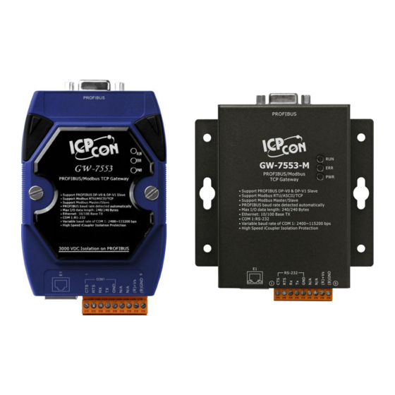
PROFIBUS and Modbus are two kinds of famous protocols and are wildly used in the fields of factory and process automation. The GW-7553-B / GW-7553-M is a PROFIBUS to Modbus TCP gateway. By using this module, users can easily put the Modbus TCP devices into PROFIBUS network. -
Page 5: Features
The main features and specification of GW-7553-B / GW-7553-M are described as below: 1.1 Features 16-bit Microprocessor inside with 80MHz ● Profichip VPC3+C PROFIBUS controller ● Support PROFIBUS DP-V0 & DP-V1 slave ● PROFIBUS transmission rate detect automatically ● Max transmission speed up to 12 Mbps for PROFIBUS and 115.2 kbps for ●... - Page 6 Table 2 LED status indicator Show the power state PWR LED Show data state Show error state ERR LED Show communication state of PROFIBUS RUN LED GW-7553-B / GW-7553-M PROFIBUS/Modbus TCP Gateway User Manual (Version 1.35, May/2017) PAGE: 6...
-
Page 7: Hardware
2. Hardware 2.1 Block Diagram of GW-7553-B / GW-7553-M Figure 2 Block diagram of GW-7553-B / GW-7553-M 2.2 Pin Assignment GW-7553-B / GW-7553-M PROFIBUS/Modbus TCP Gateway User Manual (Version 1.35, May/2017) PAGE: 7... - Page 8 Request to Send of RS-232 Receive Data of RS-232 Transmit Data of RS-232 GND of RS-232 V+ of Power Supply(+10 ~ +30 V GND of Power Supply Table 4 RJ-45 socket GW-7553-B / GW-7553-M PROFIBUS/Modbus TCP Gateway User Manual (Version 1.35, May/2017) PAGE: 8...
-
Page 9: Wiring
It is recommended to use only one communication interface (RS- 232 or Ethernet) of the Gateway at the same time. The following section describes the connection interface of GW-7553-B / GW-7553-M. 2.3.1 RS-232 connection GW-7553-B / GW-7553-M PROFIBUS/Modbus TCP Gateway User Manual (Version 1.35, May/2017) PAGE: 9... - Page 10 The RS-232 port of the GW-7553-B / GW-7553-M has got three pins. The wiring of the RS-232 device with the RS-232 port of the GW-7553-B / GW- 7553-M is shown in Figure 4. Figure 4 RS-232 wiring diagram 2.3.2 Ethernet connection The user can connect GW-7553-B / GW-7553-M with the other device to the same sub network or same Ethernet Switch, as shown in Figure 5.
- Page 11 2.3.3 PROFIBUS Connection The PROFIBUS interface of the GW-7553-B / GW-7553-M is a DB9 female connector. The connector uses the standard PROFIBUS 9 pin assignment. It is recommended to use a standard PROFIBUS cable and connector (DB9 male). As with every serial bus the rate of safe data transmission in a PROFIBUS network decreases with increasing distance between Master and Slave.
-
Page 12: Setting The Profibus Address
2.4 Setting the PROFIBUS Address The station address of GW-7553-B / GW-7553-M can be set by using either the GW-7553-B / GW-7553-M PROFIBUS/Modbus TCP Gateway User Manual (Version 1.35, May/2017) - Page 13 2. If the address in the EEPROM is 126, the PROFIBUS 126-254 configuration tool can set a new address and save it to the EEPROM. 1. Slave address in the EEPROM is set to 126. GW-7553-B / GW-7553-M PROFIBUS/Modbus TCP Gateway User Manual (Version 1.35, May/2017) PAGE: 13...
-
Page 14: Led Status Indicator
Slave a new address. 2.5 LED status indicator The GW-7553-B / GW-7553-M provides three LEDs to indicate the statuses of the GW-7553-B / GW-7553-M module. The position of LEDs and descriptions are shown in Table 9 and Figure 9. -
Page 15: Normal/Setting Dip Switch
Figure 9 LED position 2.6 Normal/Setting DIP switch There is a DIP switch on the back of the GW-7553-B module, as shown in Figure 10. GW-7553-B / GW-7553-M PROFIBUS/Modbus TCP Gateway User Manual (Version 1.35, May/2017) PAGE: 15... - Page 16 The DIP switch is used to set the GW-7553-B module works in operation mode or setting mode. In the normal situation, it needs to set the DIP switch to the “Normal” position. In this case, the GW-7553-B module can communicate with Modbus devices.
-
Page 17: Communication Protocol Transfer Theorem
3. Communication protocol transfer theorem 3.1 PROFIBUS data exchange The GW-7553-B / GW-7553-M is a PROFIBUS DP Slave device. The GW-7553- B / GW-7553-M is first parameterized then configured and finally it goes into the data exchange mode (Figure 11). - Page 18 GW-7553-M The GW-7553-B / GW-7553-M downloads the parameter and configuration from PROFIBUS Master device to be the module parameters. The GW-7553-B / GW- 7553-M and PROFIBUS Master device have different data type and data address, the GW-7553-B / GW-7553-M can transfer different data format to PROFIBUS Master device through module parameters.
- Page 19 Figure 13 The output data of PROFIBUS Master device send to the GW-7553-B / GW-7553-M Figure 14 The input data of PROFIBUS Master device receive from the GW-7553-B / GW-7553-M When the GW-7553-B / GW-7553-M acts as a Modbus Slave device, it will send DO、AO data to input data area of PROFIBUS Master device and it will save data...
-
Page 20: Modbus Data Exchange
Figure 15 The output data of PROFIBUS Master device send to the GW-7553-B / GW-7553-M Figure 16 The input data of PROFIBUS Master device receive from the GW-7553- B / GW-7553-M 3.2 Modbus data exchange Modbus protocol belongs to Master-Slave communication and it uses query and response message to arrive at data exchange and device control, as shown in GW-7553-B / GW-7553-M PROFIBUS/Modbus TCP Gateway User Manual (Version 1.35, May/2017) - Page 21 Figure 17 Data exchange between the Modbus devices and the GW-7553-B / GW- 7553-M When the GW-7553-B / GW-7553-M acts as a Modbus Master device, it can get query message through module parameter and DO、AO data and send query message to Modbus Slave device. It can also receive response message form Modbus Slave device and then saving to internal DI、AI memory space, as...
- Page 22 Figure 18 GW-7553-B / GW-7553-M output data to Modbus Slave devices Figure 19 GW-7553-B / GW-7553-M receive data from Modbus Slave devices When the GW-7553-B / GW-7553-M acts as a Modbus Slave device, it can receive query message from Modbus Master device and then saving to internal DO、AO memory space.
-
Page 23: Communication Protocol Transfer
3.3 Communication protocol transfer In section 3.1 and 3.2, we can understand that data exchange is through DI、 DO 、 AI 、 AO memory space of the GW-7553-B / GW-7553-M between GW-7553-B / GW-7553-M PROFIBUS/Modbus TCP Gateway User Manual (Version 1.35, May/2017) - Page 24 PROFIBUS Master、Modbus and the GW-7553-B / GW- 、 7553-M, as shown in Figure 22 Figure 23. Figure 22 GW-7553-B / GW-7553-M (master mode) communication protocol transfers GW-7553-B / GW-7553-M PROFIBUS/Modbus TCP Gateway User Manual (Version 1.35, May/2017) PAGE: 24...
- Page 25 Figure 23 GW-7553-B / GW-7553-M (master mode) flowchart GW-7553-B / GW-7553-M PROFIBUS/Modbus TCP Gateway User Manual (Version 1.35, May/2017) PAGE: 25...
- Page 26 When the GW-7553-B / GW-7553-M acts as a Modbus Slave device, the data exchange runs continuously between PROFIBUS Master and the GW-7553-B / GW-7553-M and the data exchange runs between Modbus Master device and the GW-7553-B / GW-7553-M, when GW-7553-B / GW-7553-M receive query 、...
- Page 27 Figure 25 GW-7553-B / GW-7553-M (slave mode) flowchart GW-7553-B / GW-7553-M PROFIBUS/Modbus TCP Gateway User Manual (Version 1.35, May/2017) PAGE: 27...
-
Page 28: Profibus Dp-V1 Acyclic Service
C2-IDLE, DP-slave will terminate this connection automatically. The Information in DP-V1 is addressing by Slot and Index. The slot(0~255) addresses the module and the index(0~255) addresses the data blocks assigned to GW-7553-B / GW-7553-M PROFIBUS/Modbus TCP Gateway User Manual (Version 1.35, May/2017) PAGE: 28... - Page 29 1 = write constrain conflict 2 = resource busy 3 = resource unavailable 4 to 7 = reserved 8 to 15 = user specific Figure 26 Error code/Error class GW-7553-B / GW-7553-M PROFIBUS/Modbus TCP Gateway User Manual (Version 1.35, May/2017) PAGE: 29...
- Page 30 Slot 1 is used for the system setting module. Because the user must add “System setting module” at the first module before the other modules, else the GW-7553-B / GW-7553-M will send the diagnostic messages to PROFIBUS Master and the system will be abnormal.
- Page 31 2 bytes digital output module : slot -> 2, index -> 0~15 , length -> 1 4 words analog input module : slot -> 3, index -> 0~3 , length -> 2 GW-7553-B / GW-7553-M PROFIBUS/Modbus TCP Gateway User Manual (Version 1.35, May/2017) PAGE: 31...
-
Page 32: Communication
(Figure 27) or a multi-master system (Figure 28). The GW- 7553-B / GW-7553-M enables the integration of the Modbus devices into a PROFIBUS DP network. Figure 27 Mono-master system GW-7553-B / GW-7553-M PROFIBUS/Modbus TCP Gateway User Manual (Version 1.35, May/2017) PAGE: 32... -
Page 33: Gsd File
The parameters(ex: baud rate, message length, number of input / output data and etc. ) of each PROFIBUS DP device are described in a GSD file. The GSD file of the GW-7553-B / GW-7553-M can be form the ICP DAS companion CD-ROM (PATH --> CD: \PROFIBUS\GATEWAY\GW-7553 \GSD\). - Page 34 7 Manager. Figure 29 install GSD file Step 3: Click “Browse” button to choose where the GSD file located Figure 30 choose the path where GSD file located. GW-7553-B / GW-7553-M PROFIBUS/Modbus TCP Gateway User Manual (Version 1.35, May/2017) PAGE: 34...
-
Page 35: The Configuration Of The Common Parameters
GW-7552-B is successfully added. Figure 32 Finish adding the GW-7552-B 4.3 The Configuration of the common parameters GW-7553-B / GW-7553-M has twelve common parameters. The user can GW-7553-B / GW-7553-M PROFIBUS/Modbus TCP Gateway User Manual (Version 1.35, May/2017) PAGE: 35... - Page 36 I/O safe mode = “Switch Safe Value” The GW-7553-B / GW-7553-M will set internal DIO and AIO data to safe value and send the safe values to the Modbus Slave device. I/O safe mode = “Retain Last Value”...
- Page 37 The GW-7553-B / GW-7553-M will set the internal DI and AI data to safe value and send safe values to PROFIBUS Master device. I/O safe mode = “Retain Last Value” Internal DIO and AIO data retain last value When GW-7553-B / GW-7553-M acts as a Modbus Slave (Modbus Type=Slave): i.
-
Page 38: The Configuration Of The Modules
(S) means the parameter is effective, when Modbus Type of GW-7553-B / GW-7553-M is Slave. (T) means the parameter is effective, when Modbus Format of GW-7553-B / GW-7553-M is TCP. 4.4 The Configuration of the modules The user can set the number and size of the I/O modules in the PROFIBUS configuration tool. - Page 39 ID is 2, data address is 40001~ 40004 and data count is 4 via the second TCP connection. In this case, the user can select an “Output Register => 4 Words module”, module parameters are shown in the below: GW-7553-B / GW-7553-M PROFIBUS/Modbus TCP Gateway User Manual (Version 1.35, May/2017) PAGE: 39...
-
Page 40: Diagnostic Messages
Start Address:The GW-7553-B / GW-7553-M and Modbus Slave device exchange data from this starting address. d. NO. of Relay/Coil:It is data size that the GW-7553-B / GW-7553-M and Modbus Slave device exchange. e. Module type:The user can select data type for data exchange by this setting. -
Page 41: Data Error
PROFIBUS lose input data.(0x3C) Data Error Lose PROFIBUS output data.(0x3F) “*” These error messages are not supported when the GW-7553-B / GW-7553-M act as a Modbus Slave. Diagnostic message will shown in input data area of System setting module (Please refer to section 4.6.1) Data Error:... -
Page 42: I/O Data Exchange
PROFIBUS Master. 4.6 I/O data exchange The I/O data exchange is decided by Modbus type of the GW-7553-B / GW-7553- M (please refer section 4.3 The Configuration of the common parameters) between PROFIBUS Master device and the GW-7553-B / GW-7553-M. Output... - Page 43 Table 16. The user can change data and I/O state of Modbus Slave device or DI/DO/AI/AO data of GW-7553-B / GW-7553-M by modify data of output module. Table 16 Output data area...
- Page 44 When Modbus type is Master When this byte is changed, PROFIBUS Master device will send data of output module to DO/AO data of GW-7553-B / GW-7553-M and then GW-7553-B / GW-7553-M will send query message to Modbus Slave device for change data or output state of Modbus Slave device.
-
Page 45: Establish Connection With Gw-7553-B / Gw-7553-M
) 4.7 Establish connection with GW-7553-B / GW-7553-M Before establishing a connection between the DP-Master and the GW-7553-B / GW-7553-M, user should execute the following steps first. Figure 33 Establish connection with GW-7553-B / GW-7553-M First, users must load the electronic device description file (GSD file) of the GW- GW-7553-B / GW-7553-M PROFIBUS/Modbus TCP Gateway User Manual (Version 1.35, May/2017) -
Page 46: Data Exchange Example-Modbus Rtu
GW-7553-B / GW-7553-M proceeds into data exchange state. Users can observe the status indicator LED to know the state of GW-7553-B / GW-7553-M. At the meantime, if there is any error occurs, GW-7553-B / GW- 7553-M will return to wait parameterization. - Page 47 Add GW-7553-B , double click the GW-7553-B icon to choose “Profibus” and check the Profibus address is “1” then click “OK” Figure 36 Click “Parameter Data…” button to open the “Parameter Data” window GW-7553-B / GW-7553-M PROFIBUS/Modbus TCP Gateway User Manual (Version 1.35, May/2017) PAGE: 47...
- Page 48 Figure 37 The user needs to change “Modbus Type” to Slave and “Modbus Format” to Modbus RTU for this example and click “OK” button Step 4: Set the GW-7553-B modules, as shown in Figure 38 and Figure 39. Select “System setting” module: “System setting” module always has to be selected otherwise no communication can be established between the gateway and the Modbus network.
- Page 49 -- Start the test utility “MBRTU” (Figure 41) on the PC. This utility simulates a Modbus Master device and is on the web site in the following directory: GW-7553-B / GW-7553-M PROFIBUS/Modbus TCP Gateway User Manual (Version 1.35, May/2017) PAGE: 49...
- Page 50 00 00 00 10 54 07”). The user can find byte 6, 7 of the input data area in the configuration program “Step 7” have changed into “0xFF” at this time, as shown in the below. GW-7553-B / GW-7553-M PROFIBUS/Modbus TCP Gateway User Manual (Version 1.35, May/2017) PAGE: 50...
- Page 51 Figure 43 Receive “0xFF” in the input data area Table 17 Receive “0xFF” in the input data area Module Byte Data type Representation Value Input 6 Byte 0xFF Input module Input 7 Byte 0xFF GW-7553-B / GW-7553-M PROFIBUS/Modbus TCP Gateway User Manual (Version 1.35, May/2017) PAGE: 51...
- Page 52 B9 B8”). In this message, the user can know the value of DI0 & DI1 is “0” in the GW-7553-B --Send output data to write DI of the GW-7553-B by the PROFIBUS Master The user needs to set “0xFE” & “0xDC” in byte 3 & byte 4 of output data area in the configuration program “Step 7”...
- Page 53 10 79 C6” again. Then MBRTU can receive response message (” 01 02 02 FE DC F8 41”). In this message, the user can know the value of DI0 & DI1 have changed into “0xFE” & “0xDC” in the GW-7553-B, as shown in Figure 44, Figure 45 , Figure 46 & Table 18...
- Page 54 Byte 0x00 0x01 System Output 1 Byte 0x00 module Output 2 Byte 0x00 → Output 3 Byte 0x00 0xFE Output module → Output 4 Byte 0x00 0xDC GW-7553-B / GW-7553-M PROFIBUS/Modbus TCP Gateway User Manual (Version 1.35, May/2017) PAGE: 54...
- Page 55 Figure 46 Send Modbus command to read DI of the GW-7553-B and receive data (0xFE, 0xDC) Modbus command: Query message (Hi) (Lo) (Hi) (Lo) check Response message DATA check GW-7553-B / GW-7553-M PROFIBUS/Modbus TCP Gateway User Manual (Version 1.35, May/2017)
-
Page 56: Data Exchange Example-Modbus Tcp
B are used. The configuration and communication is done by the program “Step 7 Manager” provided by SIEMENS. Step 1: Copy the GSD file and assign the GW-7553-B a valid station address (Please refer to the section 4.2 GSD file). - Page 57 Figure 47 Wiring diagram between PC and GW-7553-B Step 3: Set the parameters of the GW-7553-B . We need to change “Modbus Type” to Slave and “Modbus Format” to Modbus TCP. The default setting is being used in the other parameters for this example. Please refer to section 4.3 the Configuration of the common parameters.
- Page 58 Figure 50 The user needs to change “Modbus Type” to Slave and “Modbus Format” to Modbus TCP for this example and click “OK” button Step 4: Set the GW-7553-B modules, as shown in Figure 81 and Figure 82. Select “System setting” module: “System setting” module always has to be selected otherwise no communication can be established between the gateway and the Modbus network.
- Page 59 Step 5: Save and complie Figure 53 Download to PLC Step 6: Now the setting done by the Step 7 has to be downloaded to the PROFIBUS Master. GW-7553-B / GW-7553-M PROFIBUS/Modbus TCP Gateway User Manual (Version 1.35, May/2017) PAGE: 59...
- Page 60 This utility simulates a Modbus Master device and is on the web site in the following directory: http://ftp.icpdas.com.tw/pub/cd/8000cd/napdos/modbus/modbus_utility/ (1) Set the IP address of the GW-7553-B (2) Click the connect button GW-7553-B / GW-7553-M PROFIBUS/Modbus TCP Gateway User Manual (Version 1.35, May/2017) PAGE: 60...
- Page 61 00 10”). The user can find byte 6, 7 of the input data area in the configuration program “Step 7” have changed into “0xFF” at this time, as shown below. GW-7553-B / GW-7553-M PROFIBUS/Modbus TCP Gateway User Manual (Version 1.35, May/2017) PAGE: 61...
- Page 62 Table 19 Receive “0xFF” in the input data area Module Byte Data type Representation Value Input 6 Byte 0xFF Input module Input 7 Byte 0xFF Modbus command: Query message DATA (Hi) (Lo) (Hi) (Lo) GW-7553-B / GW-7553-M PROFIBUS/Modbus TCP Gateway User Manual (Version 1.35, May/2017) PAGE: 62...
- Page 63 MBTCP can receive response message (” 01 02 02 00 00”). In this message, the user can know the value of DI0 & DI1 is “0” in the GW-7553-B. --Send output data to write DI of the GW-7553-B by the PROFIBUS Master The user needs to set “0xFE”...
- Page 64 Figure 56 Send Modbus command to read DI of the GW-7553-B Figure 57 Set output data and trigger output data command in the output data area GW-7553-B / GW-7553-M PROFIBUS/Modbus TCP Gateway User Manual (Version 1.35, May/2017) PAGE: 64...
- Page 65 Byte 0x00 0xFE Output module → Output 4 Byte 0x00 0xDC Figure 58 Send Modbus command to read DI of the GW-7553-B and receive data (0xFE, 0xDC) GW-7553-B / GW-7553-M PROFIBUS/Modbus TCP Gateway User Manual (Version 1.35, May/2017) PAGE: 65...
- Page 66 The configuration and communication is done by the program “SyCon” provided by Hilscher. Step 1: Copy the GSD file and assign the GW-7553 a valid station address (Please refer to the section 4.2 GSD file). GW-7553-B / GW-7553-M PROFIBUS/Modbus TCP Gateway User Manual (Version 1.35, May/2017) PAGE: 66...
- Page 67 Configuration of the common parameters. The users can set parameters as shown in the below. Double click the GW-7553 icon to open the “Slave configuration” Figure 60 GW-7553-B / GW-7553-M PROFIBUS/Modbus TCP Gateway User Manual (Version 1.35, May/2017) PAGE: 67...
- Page 68 “OK” button Step 4: Set the GW-7553 modules, as shown in Figure 38 and Figure 39. Select “System setting” module: “System setting” module always has GW-7553-B / GW-7553-M PROFIBUS/Modbus TCP Gateway User Manual (Version 1.35, May/2017) PAGE: 68...
- Page 69 Select “Output Relay/Coil” module: In this example a “ Output ” module is selected. Register--1 word Figure 63 Double click the GW-7553 icon to open the “Slave configuration” window GW-7553-B / GW-7553-M PROFIBUS/Modbus TCP Gateway User Manual (Version 1.35, May/2017) PAGE: 69...
- Page 70 Step 6: Now the setting done by the configuration tool has to be downloaded to the PROFIBUS Master. Click on the Master area in the graphic window then Online -> Download… GW-7553-B / GW-7553-M PROFIBUS/Modbus TCP Gateway User Manual (Version 1.35, May/2017) PAGE: 70...
- Page 71 (1) Set the COM Port number of the PC (2) Set the Baud rate to 115200 (3) Set the Line control to N,8,1 (4)Open the connection GW-7553-B / GW-7553-M PROFIBUS/Modbus TCP Gateway User Manual (Version 1.35, May/2017) PAGE: 71...
- Page 72 00 00 00 10 54 07”). The user can find byte 6, 7 of the input data area in the configuration program “SyCon” have changed into “0xFF” at this time, as shown in the below. GW-7553-B / GW-7553-M PROFIBUS/Modbus TCP Gateway User Manual (Version 1.35, May/2017) PAGE: 72...
- Page 73 Input 6 Byte 0xFF Input module Input 7 Byte 0xFF Modbus command: Query message DATA (Hi) (Lo) (Hi) (Lo) check Response message (Hi) (Lo) (Hi) (Lo) check GW-7553-B / GW-7553-M PROFIBUS/Modbus TCP Gateway User Manual (Version 1.35, May/2017) PAGE: 73...
- Page 74 Monitor menu. User must enter parameters relative to DPV1 in the message monitor in order to read/write data via DPV1 from a profibus slave. The message monitor is shown in Figure 69. GW-7553-B / GW-7553-M PROFIBUS/Modbus TCP Gateway User Manual (Version 1.35, May/2017) PAGE: 74...
- Page 75 If configure CIF50-PB as a class 2 master, user must establish connection. Please click Online->Message Monitor, then fill in parameters relative to Initiate request telegram, as shown in Figure 70 and Table 22. GW-7553-B / GW-7553-M PROFIBUS/Modbus TCP Gateway User Manual (Version 1.35, May/2017) PAGE: 75...
- Page 76 If configure CIF50-PB as a class 2 master,《Message Header->B》is 0x21 Please click Online->Message Monitor, then fill in parameters relative to Read request telegram, as shown in Figure 71、Figure 72 and Table 23 Telegram GW-7553-B / GW-7553-M PROFIBUS/Modbus TCP Gateway User Manual (Version 1.35, May/2017) PAGE: 76...
- Page 77 0x0A Unused Function 0x01 Read In this case, slot 3 is used for “Input Relay/Coil--2 Byte” (see Figure 39 ),the DO value of index 0 is “0x01”. GW-7553-B / GW-7553-M PROFIBUS/Modbus TCP Gateway User Manual (Version 1.35, May/2017) PAGE: 77...
- Page 78 The user needs to input command (” 01 02 00 00 00 10”) in MBRTU and click <Send Command> button to send Modbus command: “01 02 00 00 00 GW-7553-B / GW-7553-M PROFIBUS/Modbus TCP Gateway User Manual (Version 1.35, May/2017) PAGE: 78...
- Page 79 Figure 45 , Figure 46 & Table 18 Set output data and trigger output data command Figure 74 Send Modbus command to read DI of the GW-7553 GW-7553-B / GW-7553-M PROFIBUS/Modbus TCP Gateway User Manual (Version 1.35, May/2017) PAGE: 79...
- Page 80 Byte 0x00 0x01 System Output 1 Byte 0x00 module Output 2 Byte 0x00 → Output 3 Byte 0x00 0xFE Output module → Output 4 Byte 0x00 0xDC GW-7553-B / GW-7553-M PROFIBUS/Modbus TCP Gateway User Manual (Version 1.35, May/2017) PAGE: 80...
- Page 81 Figure 76 Send Modbus command to read DI of the GW-7553 and receive data (0xFE, 0xDC) Modbus command: Query message (Hi) (Lo) (Hi) (Lo) check Response message DATA check GW-7553-B / GW-7553-M PROFIBUS/Modbus TCP Gateway User Manual (Version 1.35, May/2017) PAGE: 81...
- Page 82 Step 1: Copy the GSD file and assign the GW-7553 a valid station address (Please refer to the section 4.2 GSD file). Step 2: Connect GW-7553 and PC by Figure 77. GW-7553-B / GW-7553-M PROFIBUS/Modbus TCP Gateway User Manual (Version 1.35, May/2017) PAGE: 82...
- Page 83 4.3 the Configuration of the common parameters. The users can set parameters as shown below. Figure 78 Double click the GW-7553 icon to open the “Slave configuration” window GW-7553-B / GW-7553-M PROFIBUS/Modbus TCP Gateway User Manual (Version 1.35, May/2017) PAGE: 83...
- Page 84 Modbus network. Select “Output Relay/Coil” module: In this example an “Output Relay/Coil--2 Byte” module is selected. GW-7553-B / GW-7553-M PROFIBUS/Modbus TCP Gateway User Manual (Version 1.35, May/2017) PAGE: 84...
- Page 85 Figure 82 Select modules Step 5: Close the “Slave Configuration” window by clicking the “OK” button. Step 6: Now the setting done by the configuration tool has to be GW-7553-B / GW-7553-M PROFIBUS/Modbus TCP Gateway User Manual (Version 1.35, May/2017) PAGE: 85...
- Page 86 This utility simulates a Modbus Master device and is on the web site in the following directory: http://ftp.icpdas.com.tw/pub/cd/8000cd/napdos/modbus/modbus_utility/ (1) Set the IP address of the GW-7553 (2) Click the connect button GW-7553-B / GW-7553-M PROFIBUS/Modbus TCP Gateway User Manual (Version 1.35, May/2017) PAGE: 86...
- Page 87 00 10”). The user can find byte 6, 7 of the input data area in the configuration program “SyCon” have changed into “0xFF” at this time, as shown below. GW-7553-B / GW-7553-M PROFIBUS/Modbus TCP Gateway User Manual (Version 1.35, May/2017) PAGE: 87...
- Page 88 Table 25 Receive “0xFF” in the input data area Module Byte Data type Representation Value Input 6 Byte 0xFF Input module Input 7 Byte 0xFF Modbus command: Query message DATA (Hi) (Lo) (Hi) (Lo) GW-7553-B / GW-7553-M PROFIBUS/Modbus TCP Gateway User Manual (Version 1.35, May/2017) PAGE: 88...
- Page 89 DI0 & DI1 have changed into “0xFE” & “0xDC” in the GW-7553, as shown in Figure 87, Figure 88, Figure 89, & Table 26 Set output data and trigger output data command GW-7553-B / GW-7553-M PROFIBUS/Modbus TCP Gateway User Manual (Version 1.35, May/2017) PAGE: 89...
- Page 90 Figure 87 Send Modbus command to read DI of the GW-7553 GW-7553-B / GW-7553-M PROFIBUS/Modbus TCP Gateway User Manual (Version 1.35, May/2017) PAGE: 90...
- Page 91 Byte 0x00 0xFE Output module → Output 4 Byte 0x00 0xDC Figure 89 Send Modbus command to read DI of the GW-7553 and receive data (0xFE, 0xDC) GW-7553-B / GW-7553-M PROFIBUS/Modbus TCP Gateway User Manual (Version 1.35, May/2017) PAGE: 91...
- Page 92 SA(Hi): Start Address(Hi byte)-0x00 SA(Lo): Start Address(Lo byte)-0x00 NO(Hi): No. Of points(Hi byte)-0x00 NO(Lo): No. Of points (Lo byte)-0x10 BC: Byte Count-0x02 GW-7553-B / GW-7553-M PROFIBUS/Modbus TCP Gateway User Manual (Version 1.35, May/2017) PAGE: 92...
-
Page 93: Application Of Utility
Figure 90 Install the utility Step 3: Click the “Next” button to continue. If you want to change the installation destination, click “Browse” button to set the installation path. GW-7553-B / GW-7553-M PROFIBUS/Modbus TCP Gateway User Manual (Version 1.35, May/2017) PAGE: 93... - Page 94 Figure 91 Set the installation path Step 4: Click the “Next” button to confirm installation Figure 92 Confirm installation GW-7553-B / GW-7553-M PROFIBUS/Modbus TCP Gateway User Manual (Version 1.35, May/2017) PAGE: 94...
- Page 95 After finishing the installation of the PROFIBUS/Modbus Gateway Utility, users can find the Utility as shown in the following screen shot. Figure 94 The path of Utility GW-7553-B / GW-7553-M PROFIBUS/Modbus TCP Gateway User Manual (Version 1.35, May/2017) PAGE: 95...
-
Page 96: Utility Introduction
5.2 Utility introduction By this utility, the user can understand the module address of PROFIBUS、 Modbus and the GW-7553-B / GW-7553-M. The utility also support users set safe value and network setting easily. It introduces main window of the utility first as shown in Figure 95. - Page 97 4. Data bit: 8 data bit 5. Stop bit: 1 stop bit 5.2.3 Module state: It can display the number of modules in the GW-7553-B / GW-7553-M and display module parameters in the window of the module parameter by click the module‟s icon.
-
Page 98: Memory Address Configuration Of The Module
There are 3 kinds of memory address configuration. They are (1)Space configuration in device 、 (2) Space configuration in PROFIBUS 、 (3)Space configuration in Modbus, as shown in Figure 96. Figure 96 The menu of space configuration GW-7553-B / GW-7553-M PROFIBUS/Modbus TCP Gateway User Manual (Version 1.35, May/2017) PAGE: 98... - Page 99 5.3.1 Space configuration in device: The user can select check box of the module to show memory address configuration of DI/DO/AI/AO in the GW-7553-B / GW-7553-M, as shown in Figure 97. Figure 97 Space configuration in device 5.3.2 Space configuration in PROFIBUS:...
- Page 100 Modbus ID is repeat in these modules. The data may be read and written by different modules at this time, it may make the data transmit and device control error easy because address configuration and Modbus ID overlap. GW-7553-B / GW-7553-M PROFIBUS/Modbus TCP Gateway User Manual (Version 1.35, May/2017) PAGE: 100...
-
Page 101: Safe Value Setting
Figure 100. Figure 100 The menu of safe value setting The window of “Safe Value Setting” divided into 6 parts to explain, as shown in Figure 101. GW-7553-B / GW-7553-M PROFIBUS/Modbus TCP Gateway User Manual (Version 1.35, May/2017) PAGE: 101... - Page 102 “Input” button to show safe value setting of DI/AI, click “Save to File” button to open “save file dialog” to save safe value setting for backup, click “Save to Device” button to save safe value setting to EEPROM of the GW-7553-B / GW- 7553-M.
-
Page 103: Ip Setting
Figure 102 The menu of IP setting The window of “IP Setting” divided into 3 parts to explain, as shown in Figure 103. (1) Local IP Setting: GW-7553-B / GW-7553-M PROFIBUS/Modbus TCP Gateway User Manual (Version 1.35, May/2017) PAGE: 103... -
Page 104: Establish Connection With Gw-7553-B / Gw-7553-M
“Save to Device” button to save IP setting to EEPROM of the GW-7553-B / GW-7553-M. Note: If IP setting is ok, user needs to restart GW-7553-B / GW-7553-M to read new IP setting value. Figure 103 IP setting 5.6 Establish connection with GW-7553-B / GW-7553-M... - Page 105 7553-B / GW-7553-M and enter data exchange mode (please refer step 1~6 of section 4.8 PROFIBUS and Modbus data exchange demo for detail). The RUN LED of GW-7553-B / GW-7553-M is going to light at this time. Figure 104 The connection of Utility and GW-7553-B / GW-7553-M...
- Page 106 Figure 105 Open Utility Step 5: Set COM Port communication setting of Utility (please refer section 5.2.2 COM Port settings) the same as COM Port setting of GW-7553-B / GW- 7553-M(please refer section 4.3 The Configuration of the common parameters) Step 6: Click “Communication=>Connect”...
- Page 107 Figure 107 Display connection state GW-7553-B / GW-7553-M PROFIBUS/Modbus TCP Gateway User Manual (Version 1.35, May/2017) PAGE: 107...
-
Page 108: Configuration With Web Browser
6. Configuration with Web Browser 6.1 Connecting to Web Server Open web browser (ex. IE) and enter the IP address of the GW-7553-B / GW- 7553-M module in the Address field and press “Enter” to connect to GW-7553-B / GW-7553-M module, as shown in Figure 108... -
Page 109: Web Configuration-Function Menu
Figure 110 IP address 6.2 Web Configuration—Function menu The left side is the function menu and the other is the setup page in the first page. GW-7553-B / GW-7553-M PROFIBUS/Modbus TCP Gateway User Manual (Version 1.35, May/2017) PAGE: 109... -
Page 110: Web Configuration-Setup Page
Safe Value Setting Communication Log Information Reboot The “Reboot” button can provide the user to restart the GW-7553-B / GW- 7553-M, when user login successfully. 6.3 Web Configuration—Setup page A. Login The user login and logout interface, as shown in Figure 111... - Page 111 (1) New Setting:Open a new IP setting (2) Load From Device:Load the IP setting from GW-7553-B / GW-7553-M (3) Local IP Setting:The user can set local IP setting of GW-7553-B / GW- 7553-M in this part. (4) Remote IP Setting:The user can set IP address, time out value and reconnecting time of the Modbus TCP Slave in this part.
- Page 112 The user can set safe value setting in this page, as shown in Figure 114. User select the module and press “Enter” to show the safe value setting of this module and it will save the safe value setting to EEPROM of GW-7553-B / GW-7553-M when user press “Save to Device”.
- Page 113 Figure 114 Safe Value Setting E. Communication Log The user can monitor communication between GW-7553-B / GW-7553-M and Modbus devices in this page, as shown in Figure 115. GW-7553-B / GW-7553-M PROFIBUS/Modbus TCP Gateway User Manual (Version 1.35, May/2017) PAGE: 113...
- Page 114 (1)PROFIBUS INFO、(2)MODULE LIST、(3)DIAGNOSTIC INFO、 (4)DEVICE INFO, as shown in the below. Figure 116 Information (1) PROFIBUS INFO: a. PROFIBUS Status:This page shows PROFIBUS mode、 PROFIBUS address and PROFIBUS baudrate. GW-7553-B / GW-7553-M PROFIBUS/Modbus TCP Gateway User Manual (Version 1.35, May/2017) PAGE: 114...
- Page 115 Common Parameters:This page shows common parameters of PROFIBUS. c. Module Parameters:This page shows the module parameters of each module. GW-7553-B / GW-7553-M PROFIBUS/Modbus TCP Gateway User Manual (Version 1.35, May/2017) PAGE: 115...
- Page 116 Figure 117 Module List (3) DIAGNOSTIC INFO: When PROFIBUS state is online, this page will shows the diagnostic messages of GW-7553-B / GW-7553-M, as shown in Figure 118. GW-7553-B / GW-7553-M PROFIBUS/Modbus TCP Gateway User Manual (Version 1.35, May/2017) PAGE: 116...
- Page 117 Figure 118 Diagnostic info (4) DEVICE INFO: This page shows the device information of GW-7553-B / GW-7553- M, as shown in Figure 119. Figure 119 Device info GW-7553-B / GW-7553-M PROFIBUS/Modbus TCP Gateway User Manual (Version 1.35, May/2017) PAGE: 117...
-
Page 118: Troubleshooting
GW-7553-B / GW-7553-M in the PROFIBUS Master station are not correct. It means the GW-7553-B / GW-7553-M is in setting mode and 'ERR' LED indication of the connects with Utility. Please close Utility and set the GW-7553- GW-7553-B / GW-7553-M B / GW-7553-M to operation mode (please refer section 2.6... - Page 119 0 to trigger the output command, when output data can not send to Modbus device in output data area of PROFIBUS Master (please refer section 4.6.2 Output data area and communication command). GW-7553-B / GW-7553-M PROFIBUS/Modbus TCP Gateway User Manual (Version 1.35, May/2017) PAGE: 119...
-
Page 120: Dimensions
8. Dimensions GW-7553-B GW-7553-B / GW-7553-M PROFIBUS/Modbus TCP Gateway User Manual (Version 1.35, May/2017) PAGE: 120... - Page 121 GW-7553-B / GW-7553-M PROFIBUS/Modbus TCP Gateway User Manual (Version 1.35, May/2017) PAGE: 121...
- Page 122 GW-7553-M GW-7553-B / GW-7553-M PROFIBUS/Modbus TCP Gateway User Manual (Version 1.35, May/2017) PAGE: 122...
Need help?
Do you have a question about the GW-7553-B and is the answer not in the manual?
Questions and answers