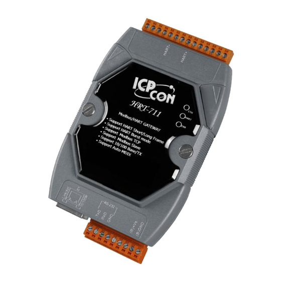
ICP DAS USA HRT-711 User Manual
Hide thumbs
Also See for HRT-711:
- User manual (54 pages) ,
- Quick start manual (9 pages) ,
- User manual (20 pages)
Table of Contents
Advertisement
Quick Links
Advertisement
Table of Contents

Summary of Contents for ICP DAS USA HRT-711
- Page 8 ...
- Page 15 Ω...
- Page 18 ’...
- Page 37 ...
- Page 38 ...
- Page 39 ...
- Page 40 ...
- Page 41 ...
- Page 42 ...
- Page 43 ...
- Page 56 “Dip Switch” “Normal”...
- Page 58 “ “...
- Page 66 [ Ex1 => The Default CMD(3) of “HART Device 0 & 1” in HRT-710 is Polling Mode ] < 1. The setting of SWAP Mode is “None” (without Byte and WORD swap) > “Device (1) Address 1000 (Unit: WORD) : Show the comm. status of 0”.
- Page 67 < 2. The setting of SWAP Mode is ”W&B” (with Byte and WORD swap) > “Device (1) Address 1001 (Unit: WORD) : Show the comm. status of 0”. [1] High Byte : “The comm. status of Default CMD(0) in device 0. [2] Low Byte : “The comm.
- Page 75 ” ”...
- Page 78 In the ”Device Configuration” page, click the ”Save to File” button to save the current settings of HRT-711 to file.
- Page 79 In the ”Device Configuration”, click the ”Load From File” button and choose the setting file of HRT-711. Then it will show all the settings in the HG_Tool. Click the ”Save to Device” button to set the settings to HRT-711 module.
- Page 80 A15: (2015/12/23) 1. Add the HART command for writing in HRT-711. (The HART cmd 19 is used in the below example => Final Assembly Number) In the ”Device Configuration” page, click the right button of mouse on the “HART Device 0” item and choose the ”Add Command”...
- Page 81 2. Set the value for the HART writing command. (HART command sent not yet) There are three bytes parameters for HART command 19. For example, the value for these three bytes parameters is 11(0x0B), 22(0x16), 33(0x21) for writing, and the Modbus command will be as below. =>...
- Page 82 After sending the above Modbus command, users can check if these values have been set successfully via HG_Tool. [1] In the”Device Information” page, click the right button of mouse on the ”User CMD(19)” item and choose the ”Advanced operation” option. [2] In the ”I/O Data”...
- Page 83 3. Trig the HRT-711 to send the UserCMD0 (HART command 19). Stop the original HART polling command and send the UserCMD0. The Modbus command will be as below. => 01 10 01 F4 00 03 06 00 00 00 A7 0A : Stop all the original HART polling command.
- Page 84 : recover all the original HART polling command. 1. Add HART CMD 48 to HRT-710. Figure 17-1 Add HART CMD 48 to HRT-710 2. In the ”Device Configuration” screen, click the ”Save to Device” button to save the settings to HRT-710. Figure 17-2 Save the settings to HRT-710...
- Page 85 3. Get HART CMD48 data via Modbus. (1) Open the ”Address Map” screen and click the “UserCMD(48)“ item. In the “Modbus AI” area, it will show the Modbus data address of UserCMD(48) with blue grid. => The response data length of HART CMD 48 will be 27Bytes (ResCode(2) and ResData(25)). Therefore, it will occupy 14 WORD Modbus address as below address 0 ~ 13.
- Page 86 Figure 17-5 Get the HART CMD 48 data by using “HC_Tool (HART Master)” “HRT-711 Utility” “Ethernet” ”Search Servers” button...
- Page 87 ”HRT-711” item and click the ”Configuratino (UDP)” ”OK”...
- Page 88 “HRT-711 Utility” “HART” “Dip Switch” “Init”...
- Page 89 ”Communication Settings” ”HRT-711” ”OK” ”Connect” “ON” of the traffic light...
- Page 90 “Q01 : How to add HART devices to HRT-711 ?” “Q02 : How to make sure that HRT-711 gets the HART device data correctly ?” “Dip Switch” ”Normal” “Q03 : How to map HART device CMD(3) data directly to SCADA or...


Need help?
Do you have a question about the HRT-711 and is the answer not in the manual?
Questions and answers