ICP DAS USA tGW-700 Series User Manual
Hide thumbs
Also See for tGW-700 Series:
- User manual (73 pages) ,
- User manual (61 pages) ,
- User manual (87 pages)
Table of Contents
Advertisement
tGW-700 Series
GW-2200 Series
User Manual
Tiny Modbus/TCP to RTU/ASCII Gateway
W
ARRANTY
All products manufactured by ICP DAS are warranted
against defective materials for a period of one year
from the date of delivery to the original purchaser.
W
ARNING
ICP DAS assumes no liability for damages consequent
to the use of this product. ICP DAS reserves the right to
change this manual at any time without notice. The
information furnished by ICP DAS is believed to be
accurate and reliable. However, no responsibility is
assumed by ICP DAS for its use, nor for any
infringements of patents or other rights of third parties
resulting from its use.
C
OPYRIGHT
Copyright © 2020 by ICP DAS. All rights are reserved.
T
RADEMARKS
Names are used for identification purposes only and
may be registered trademarks of their respective
companies.
C
U
ONTACT
S
If you have any questions, please feel free to contact
us via email at:
service@icpdas.com
Ver. 2.6, Oct. 2020
S
UPPORT
This manual relates to the following modules:
tGW-712, tGW-722, tGW-732
tGW-715, tGW-725, tGW735
tGW-718, tGW-724, tGW-734
tGW-712i, tGW-722i, tGW-732i
tGW-715i, tGW-725i, tGW735i
tGW-718i, tGW-724i, tGW-734i
tGW-718i-D
tGW-715-T, tGW-715i-T,
tGW-718-T, tGW-718i-T,
GW-2212i, GW-2222i, GW-2232i
GW-2215i, GW-2225i, GW-2235i
Advertisement
Table of Contents

Related Manuals for ICP DAS USA tGW-700 Series


Summary of Contents for ICP DAS USA tGW-700 Series
- Page 1 Series GW-2200 Series User Manual Tiny Modbus/TCP to RTU/ASCII Gateway Ver. 2.6, Oct. 2020 ARRANTY UPPORT All products manufactured by ICP DAS are warranted This manual relates to the following modules: against defective materials for a period of one year tGW-712, tGW-722, tGW-732 from the date of delivery to the original purchaser.
-
Page 2: Table Of Contents
DIN-Rail Mounting .................................- 16 - IMENSIONS ..................................- 17 - tGW-700 Series Module (Unit: mm) ...........................- 17 - CA-002 Cable (Uni t: mm) ..............................- 18 - tGW-700-T Series Module (Unit: mm) ..........................- 19 - GW-2200 Series Module (Unit: mm) ...........................- 20 - SSIGNMENTS ................................ - Page 3 Tiny Modbus/TCP to RTU/ASCII Gateway GW-2212i/2222i/2232i ................................- 26 - GW-2215i/2225i/2235i ................................- 27 - RS-232/485/422 I IRING OTES FOR NTERFACES ....................- 28 - RS-232 Wiring ..................................- 28 - RS-422 Wiring ..................................- 29 - RS-485 Wiring ..................................- 29 - GETTING STARTED FOR TGW-700 / GW-2200 SERIES USING IPV4 ..............- 30 - PC........................
- Page 4 Tiny Modbus/TCP to RTU/ASCII Gateway ID................................- 75 - ODBUS CONNECTION PPLICATIONS ..........................- 76 - TCP C LIENT PPLICATIONS ..........................- 84 - MODBUS INFORMATION ..............................- 89 - ODBUS ESSAGE TRUCTURE ............................- 89 - 01(0x01) Read the Status of the Coils (Readback DOs)......................- 92 - 02(0x02) Read the Status of the I nput (Read DIs) ........................- 93 - 03(0x03) Read the Holding Registers (Readback AOs) ......................- 94 - 04(0x04) Read the Input Registers (Read AIs) .........................- 95 -...
-
Page 5: Packing List
Tiny Modbus/TCP to RTU/ASCII Gateway Packing List The tGW-700 shipping package includes the following items: tGW-700 Series Quick Start CA-002 Cable The tGW-700-T shipping package includes the following items: tGW-700-T Series Quick Start The GW-2200 shipping package includes the following items:... -
Page 6: More Information
Tiny Modbus/TCP to RTU/ASCII Gateway More Information Documentation tGW-700 Series / tGW-700-T Series https://www.icpdas.com/en/download/index.php?nation=US&kind1=&model=&kw=tGW-700 GW-2200 Series http://www.icpdas.com/en/download/index.php?nation=US&kind1=&model=&kw=GW-2200 Firmware tGW-700 Series / tGW-700-T Series https://www.icpdas.com/en/download/show.php?num=2417&nation=US&kind1=&model=&kw=tG W-700 GW-2200 Series http://www.icpdas.com/en/download/show.php?num=2750&nation=US&kind1=&model=&kw=GW -2200 Software eSearch Utility http://www.icpdas.com/en/product/guide+Software+Utility_Driver+eSearch__Utility Copyright © 2020 ICP DAS CO., Ltd. All Rights Reserved. -
Page 7: Introduction
Tiny Modbus/TCP to RTU/ASCII Gateway 1. Introduction Modbus has become the de facto standard protocol for industrial communication, and is now the most commonly available means of connecting industrial electronic devices. Modbus allows for communication between many devices connected to the same RS-485 network, for example, a system that measures temperature and humidity and communicates the results to a computer. - Page 8 Tiny Modbus/TCP to RTU/ASCII Gateway In harsh industrial environments, the tGW-700/GW-2200 series (for i version) also adds 3000 V and +/- 4 kV ESD protection component that diverts the potentially damaging charge away from sensitive circuit to protects the module and equipment from the sudden and momentary electric current.
-
Page 9: Features
Tiny Modbus/TCP to RTU/ASCII Gateway 1.1 Features Supports Modbus TCP/UDP master and slave Supports Modbus RTU/ASCII master and slave Max. connections (masters) per serial port: 32 for tGW-700 RevB version, tGW-700-T Series, GW-2200 Series 32 (tGW-71x), 16 (tGW-72x) or 10 (tGW-73x) for tGW-700 Non-RevB version ... -
Page 10: Ethernet Solutions
Tiny Modbus/TCP to RTU/ASCII Gateway 1.3 Ethernet Solutions Nowadays, the Ethernet protocol has become the foremost standard for local area networks. Connectivity via the Internet snow common in many of the latest applications from home appliances, to vending machines, to testing equipment, to UPS, etc. An Ethernet network can link office automation and industrial control networks, access remote systems and share data and information between machines from multiple vendors, and also provides a cost-effective solution for industrial control networks. -
Page 11: Web Server Technology
Tiny Modbus/TCP to RTU/ASCII Gateway 1.4 Web Server Technology Web server technology enables the tGW-700/GW-2200 to be configured via a standard web browser interface, e.g., Google Chrome, Internet Explorer, or Firefox, etc. This means that it is easy to check the configuration of the tGW-700/GW-2200 via an Ethernet network without needing to install any other software tools, thereby reducing the learning curve required for maintaining the device. -
Page 12: Hardware Information
Tiny Modbus/TCP to RTU/ASCII Gateway 2. Hardware Information This chapter provides a detailed description of the front panel, the hardware specifications, the pin assignments, the wiring notes and the dimensions for the tGW-700/GW-2200 series modules. 2.1 Specifications tGW-718 tGW-715 tGW-718i tGW-712 tGW-722 tGW-732... -
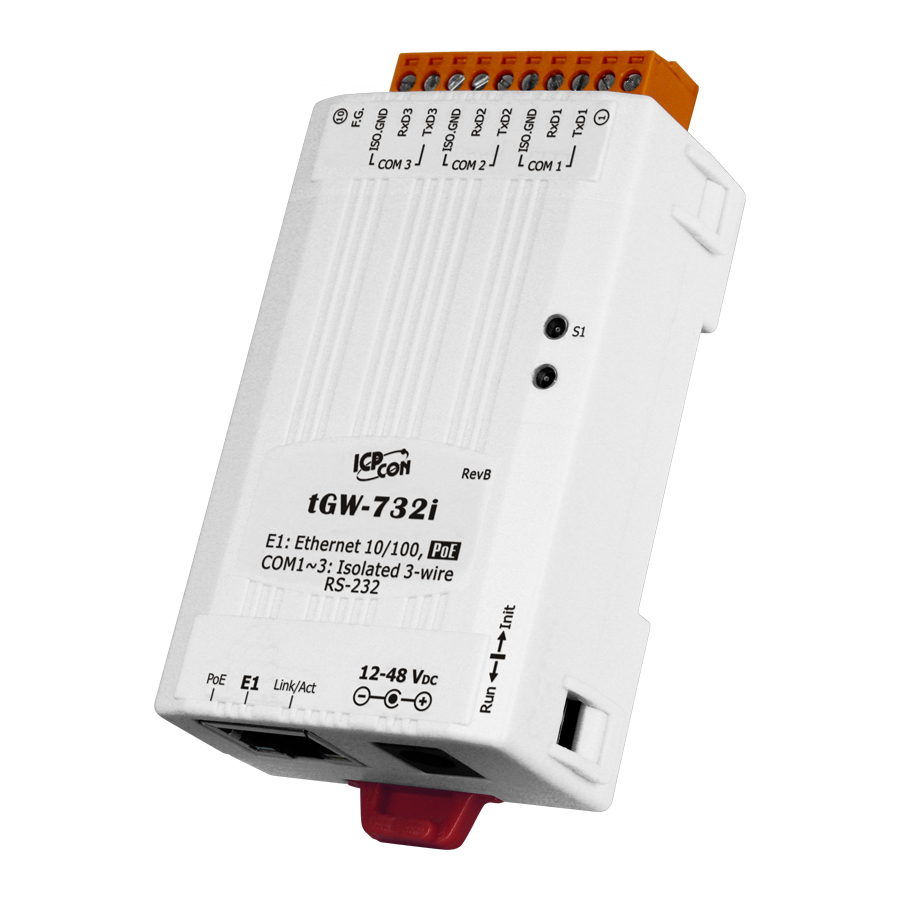
Page 13: Appearance
Tiny Modbus/TCP to RTU/ASCII Gateway 2.2 Appearance tGW-700 Series 5. Serial COM Ports 4. LED indicator 6. DIN-Rail Mounting 3. Operating Mode 1. PoE and Ethernet Switch RJ-45 Jack 2. +12 to +48 V Jack tGW-700-T Series 5. Serial COM Ports 4. -
Page 14: Poe And Ethernet Rj-45 Jack
Tiny Modbus/TCP to RTU/ASCII Gateway GW-2200 Series E TH1 supports PoE, Ethernet 2. +12 to +48 V terminal E TH2 supports Ethernet only 1. PoE and Ethernet 3. Operating Mode Switch RJ-45 Jack 4. LED indicator 6. DIN-Rail Mounting 5. -
Page 15: Operating Mode Switch
Tiny Modbus/TCP to RTU/ASCII Gateway Operating Mode Switch Run Mode: Firmware operation Init Mode: Configuration mode For tGW-700/GW-2200 series modules, the operating mode switch is set to the Run position by default. In order to update the firmware for the tGW-700/GW-2200 series module, the switch must be moved from the Run position to the Init position. -
Page 16: Serial Com Ports
Tiny Modbus/TCP to RTU/ASCII Gateway Serial COM Ports The number of serial COM Ports available depends on the type of tGW-700/GW-2200 module. For more detailed information regarding the pin assignments for the Serial COM ports, refer to Section 2.4 Pin Assignments. -
Page 17: Dimensions
The following diagrams provide the dimensions of the tGW-700/GW-2200 series module and CA-002 cable that can be used as a reference when defining the specifications and the DC power supply plug for any custom enclosures. All dimensions are in millimeters. tGW-700 Series Module (Unit: mm) tGW-712: ... -
Page 18: Cable (Unit: Mm)
Tiny Modbus/TCP to RTU/ASCII Gateway tGW-722(i)/732(i)/715(i)/725(i)/735(i)/718(i)/724(i)/734(i): CA-002 Cable (Unit: mm) Note: Cable color: BLACK Pin Assignment DESCRIPTION UNIT UL2464 18AWG 2C(RED/BLACK) OPEN 0D5.0 COLOR BLACK BLACK OPEN DC PLUG 5.5*2.1 PVC:45/P BLACK Copyright © 2020 ICP DAS CO., Ltd. All Rights Reserved. - 18 -... -
Page 19: Tgw-700-T Series Module (Unit: Mm)
Tiny Modbus/TCP to RTU/ASCII Gateway tGW-700-T Series Module (Unit: mm) tGW-715(i)-T/718(i)-T: Copyright © 2020 ICP DAS CO., Ltd. All Rights Reserved. - 19 -... -
Page 20: Gw-2200 Series Module (Unit: Mm)
Tiny Modbus/TCP to RTU/ASCII Gateway GW-2200 Series Module (Unit: mm) GW-2212i/2222i/2232i/2215i/2225i/2235i GW-2212i/2215i 1 port GW-2222i/2225i 2 ports GW-2232i/2235i 3 ports GW-2232i/2235i 3 埠 Copyright © 2020 ICP DAS CO., Ltd. All Rights Reserved. - 20 -... -
Page 21: Pin Assignments
Tiny Modbus/TCP to RTU/ASCII Gateway 2.4 Pin Assignments tGW-712/tGW-712i tGW-712 tGW-712i Terminal No. Pin Assignment COM1 CTS1 CTS1 RTS1 RTS1 ISO.GND TxD1 TxD1 RxD1 RxD1 Note: The CTS/RTS pins for flow control are supported after the firmware version B1.5.6 only. tGW-722/tGW-722i tGW-722 tGW-722i... -
Page 22: Tgw-732/Tgw-732I
Tiny Modbus/TCP to RTU/ASCII Gateway tGW-732/tGW-732i tGW-732 tGW-732i Terminal No. Pin Assignment F.G. F.G. ISO.GND COM3 RxD3 RxD3 TxD3 TxD3 ISO.GND COM2 RxD2 RxD2 TxD2 TxD2 ISO.GND COM1 RxD1 RxD1 TxD1 TxD1 tGW-715/tGW-715i/tGW-715-T/tGW-715i-T tGW-715 tGW-715i tGW-715-T tGW-715i-T Terminal No. Pin Assignment F.G. -
Page 23: Tgw-725/Tgw-725I
Tiny Modbus/TCP to RTU/ASCII Gateway tGW-725/tGW-725i tGW-725 tGW-725i Terminal No. Pin Assignment F.G. F.G. ISO.GND COM2 ISO.GND COM1 tGW-735/tGW-735i tGW-735 tGW-735i Terminal No. Pin Assignment F.G. F.G. ISO.GND COM3 ISO.GND COM2 ISO.GND COM1 Copyright © 2020 ICP DAS CO., Ltd. All Rights Reserved. - 23 -... -
Page 24: Tgw-718/Tgw-718I/Tgw-718-T/Tgw-718I-T
Tiny Modbus/TCP to RTU/ASCII Gateway tGW-718/tGW-718i/tGW-718-T/tGW-718i-T tGW-718 tGW-718i tGW-718-T tGW-718i-T Terminal No. Pin Assignment F.G. F.G. F.G. F.G. ISO.GND ISO.GND RS-232 RxD1 RxD1 RxD1 RxD1 TxD1 TxD1 TxD1 TxD1 ISO.GND ISO.GND RxD1- RxD1- RxD1- RxD1- RS-485/RS-422 RxD1+ RxD1+ RxD1+ RxD1+ TxD1-/D1- TxD1-/D1- TxD1-/D1-... -
Page 25: Tgw-724/Tgw-724I
Tiny Modbus/TCP to RTU/ASCII Gateway tGW-724/tGW-724i tGW-724 tGW-724i Terminal No. Pin Assignment F.G. F.G. ISO.GND CTS2 CTS2 RTS2 RTS2 COM2 ISO.GND RxD2 RxD2 TxD2 TxD2 ISO.GND COM1 Note: The CTS/RTS pins for flow control are supported after the firmware version B1.5.6 only. tGW-734/tGW-734i tGW-734 tGW-734i... - Page 26 Tiny Modbus/TCP to RTU/ASCII Gateway GW-2212i/2222i/2232i GW-2212i GW-2222i GW-2232i Terminal No. Pin Assignment ISO.GND RTS3 COM3 CTS3 RxD3 TxD3 ISO.GND ISO.GND RTS2 RTS2 COM2 CTS2 CTS2 RxD2 RxD2 TxD2 TxD2 ISO.GND ISO.GND ISO.GND RTS1 RTS1 RTS1 COM1 CTS1 CTS1 CTS1 RxD1 RxD1 RxD1...
- Page 27 Tiny Modbus/TCP to RTU/ASCII Gateway GW-2215i/2225i/2235i GW-2215i GW-2225i GW-2235i Terminal No. Pin Assignment ISO.GND RxD3- COM3 RxD3+ TxD3-/D3- TxD3+/D3+ ISO.GND ISO.GND RxD2- RxD2- COM2 RxD2+ RxD2+ TxD2-/D2- TxD2-/D2- TxD2+/D2+ TxD2+/D2+ ISO.GND ISO.GND ISO.GND RxD1- RxD1- RxD1- COM1 RxD1+ RxD1+ RxD1+ TxD1-/D1- TxD1-/D1- TxD1-/D1-...
-
Page 28: Wiring Notes For Rs-232/485/422 Interfaces
Tiny Modbus/TCP to RTU/ASCII Gateway 2.5 Wiring Notes for RS-232/485/422 Interfaces RS-232 Wiring 3-wire RS-232 Connection 5-wire RS-232 Connection Note: FGND is the frame ground that is soldered to the metal shield on the DB-9 cable. Copyright © 2020 ICP DAS CO., Ltd. All Rights Reserved. - 28 -... -
Page 29: Wiring
Tiny Modbus/TCP to RTU/ASCII Gateway RS-422 Wiring RS-485 Wiring Notes: 1. Usually, you have to connect all signal grounds of RS-422/485 devices together to reduce common-mode voltage between devices. 2. Twisted-pair cable must be used for the DATA+/- wires. 3. Both two ends of the cable may require a termination resistor connected across the two wires (DATA+ and DATA-). -
Page 30: Getting Started For Tgw-700 / Gw-2200 Series Using Ipv4
Tiny Modbus/TCP to RTU/ASCII Gateway 3. Getting Started for tGW-700 / GW-2200 series using IPv4 This chapter provides detailed information about the “Self-Test” process, which is used to confirm that the tGW-700/GW-2200 series module is operating correctly. Before beginning the “Self-Test” process, the wiring test, Ethernet configuration and search/Modbus utility driver installation procedures must first be fully completed. - Page 31 Ethernet Switch, and then supply power (PoE or +12 to +48 V ) to the tGW-700/GW-2200. PoE Power Supply Note: tGW-700-T series don’t support PoE. tGW-700 Series Uses PoE Switch Host PC Power over Ethernet Ethernet Cable PoE Switch (NS-205PSE)
- Page 32 Tiny Modbus/TCP to RTU/ASCII Gateway +12 to +48 V Jack Power Supply (Non-PoE) tGW-700 Series Uses Non-PoE Switch Host PC Power Supply (+12~+48V Ethernet Cable CA-002 Hub/Switch (NS-205) tGW-700-T Series Host PC Power Supply (+12~+48V Ethernet Cable Hub/Switch(NS-205) Copyright © 2020 ICP DAS CO., Ltd. All Rights Reserved.
- Page 33 Tiny Modbus/TCP to RTU/ASCII Gateway GW-2200 Series Host PC Uses Non-PoE Switch Power Supply (+12~+48V Ethernet Cable Hub/Switch(NS-205) 4. Verify that the System (S1) LED indicator is flashing. Red, OK Red, OK Copyright © 2020 ICP DAS CO., Ltd. All Rights Reserved. - 33 -...
-
Page 34: Configuring Network Settings
Tiny Modbus/TCP to RTU/ASCII Gateway 3.2 Configuring Network Settings 1. Downloaded the eSearch Utility and installed according to the installation instructions. The eSearch Utility can be obtained from the ICP DAS web site. The location of the download addresses is shown below: http://www.icpdas.com/en/product/guide+Software+Utility_Driver+eSearch__Utility 2. - Page 35 Tiny Modbus/TCP to RTU/ASCII Gateway Factory Default Settings of tGW-700/GW-2200 Series Module: IPv4 settings Wirtable IP Address 192.168.255.1 Subnet Mask 255.255.0.0 Gateway 192.168.0.1 IPv6 settings Wirtable User-defined fc00::1 Link-Local EUI-64 format SLAAC Auto-Configure 5. Enter the network settings information, including the IP, Mask, Gateway addresses, and then click “OK”...
-
Page 36: Connecting The Modbus Devices
Tiny Modbus/TCP to RTU/ASCII Gateway 3.3 Connecting the Modbus Devices Note: The wiring and supply power method depends on your Modbus device. Here, the M-7022 module is used as an example. For other Modbus device or third party Modbus device, refer to the specific Quick Start Guide or User Manual for that Modbus device. -
Page 37: Configuring The Serial Port
Tiny Modbus/TCP to RTU/ASCII Gateway 3.4 Configuring the Serial Port 1. Open a web browser, such as Google Chrome, Internet Explorer, or Firefox, and enter the URL for the tGW-700/GW-2200 module in the address bar of the browser, or click the “Web” button in the eSearch Utility. - Page 38 Tiny Modbus/TCP to RTU/ASCII Gateway 4. tGW-718i-D: Select RS-232 or RS-422/485 in the “Interface” drop down list depending on your external device type. Others: The interface is depending on your tGW-700/GW-2200 models and wirings, no interface setting on the web page. ...
-
Page 39: Self-Test
Tiny Modbus/TCP to RTU/ASCII Gateway 3.5 Self-Test 1. In the eSearch Utility, select the “Modbus TCP Master” item from the “Tools” menu to open the Modbus TCP Master Utility. 2. In the Modbus TCP Master Utility, enter the IP address of tGW-700/GW-2200 in the “Modbus TCP”... -
Page 40: Getting Started For Tgw-700 / Gw-2200 Series Using Ipv6
Tiny Modbus/TCP to RTU/ASCII Gateway 4. Getting Started for tGW-700 / GW-2200 series using IPv6 This chapter provides detailed information about the “Self-Test” process, which is used to confirm that the tGW-700/GW-2200 series module is operating correctly. Before beginning the “Self-Test” process, the wiring test, Ethernet configuration and search/Modbus utility driver installation procedures must first be fully completed. - Page 41 Ethernet Switch, and then supply power (PoE or +12 to +48 V ) to the tGW-700/GW-2200. PoE Power Supply Note: tGW-700-T series don’t support PoE. tGW-700 Series Uses PoE Switch Host PC Power over Ethernet Ethernet Cable PoE Switch (NS-205PSE)
- Page 42 Tiny Modbus/TCP to RTU/ASCII Gateway +12 to +48 V Jack Power Supply (Non-PoE) tGW-700 Series Uses Non-PoE Switch Host PC Power Supply (+12~+48V Ethernet Cable CA-002 Hub/Switch (NS-205) tGW-700-T Series Host PC Power Supply (+12~+48V Ethernet Cable Hub/Switch(NS-205) Copyright © 2020 ICP DAS CO., Ltd. All Rights Reserved.
- Page 43 Tiny Modbus/TCP to RTU/ASCII Gateway GW-2200 Series Host PC Uses Non-PoE Switch Power Supply (+12~+48V Ethernet Cable Hub/Switch(NS-205) 4. Verify that the System (S1) LED indicator is flashing. Red, OK Red, OK Copyright © 2020 ICP DAS CO., Ltd. All Rights Reserved. - 43 -...
-
Page 44: Configuring Network Settings
Tiny Modbus/TCP to RTU/ASCII Gateway 4.2 Configuring Network Settings 1. Downloaded the eSearch Utility and installed according to the installation instructions. The eSearch Utility can be obtained from the ICP DAS web site. The location of the download addresses is shown below: http://www.icpdas.com/en/product/guide+Software+Utility_Driver+eSearch__Utility Note: The version of the eSearch Utility have to v1.2.5 or later. - Page 45 Tiny Modbus/TCP to RTU/ASCII Gateway 4. Every IPv6 device has the Link-Local address. You can view the Link-Local address of the tGW-700/GW-2200 module in the “Link-Local” field without configuring. If your environment supports Stateless Address Auto-configuration (SLAAC), the SLAAC field will display the SLAAC address when the SLAAC configuration is completed.
-
Page 46: Connecting The Modbus Devices
Tiny Modbus/TCP to RTU/ASCII Gateway 4.3 Connecting the Modbus Devices Note: The wiring and supply power method depends on your Modbus device. Here, the M-7022 module is used as an example. For other Modbus device or third party Modbus device, refer to the specific Quick Start Guide or User Manual for that Modbus device. -
Page 47: Configuring The Serial Port
Tiny Modbus/TCP to RTU/ASCII Gateway 4.4 Configuring the Serial Port 1. Right Click on the Link-Local field and click the “Copy to Clipboard” to copy the “Link-Local address” of the tGW-700/GW-2200 module. 2. Paste the “Link-Local address” of the tGW-700/GW-2200 module in the address bar of the browser and add the brackets, i.e., [Link-Local address]. - Page 48 Tiny Modbus/TCP to RTU/ASCII Gateway 4. Click the “Port1” tab to display the Port1 Settings page. 5. tGW-718i-D: Select RS-232 or RS-422/485 in the “Interface” drop down list depending on your external device type. Others: The interface is depending on your tGW-700/GW-2200 models and wirings, no interface setting on the web page.
-
Page 49: Self-Test
Tiny Modbus/TCP to RTU/ASCII Gateway 7. Click “Submit” to save your settings. 4.5 Self-Test 1. Download and install the “Modbus Poll” test program at below link. https://www.modbustools.com/download.html 2. Double-click the Modbus Poll shortcut to open. 3. Select the “Read/Write Definition…” item from the “Setup” menu to open the “Read/Write Definition”... - Page 50 Tiny Modbus/TCP to RTU/ASCII Gateway 6. Configure the IPv6 address and TCP port (default : 502) of tGW-700/GW-2200 and click “OK” to connect the tGW-700/GW-2200 for testing. 7. If the response data is correct, it means the test is success. Copyright ©...
-
Page 51: Web Configuration
Tiny Modbus/TCP to RTU/ASCII Gateway 5. Web Configuration Once the tGW-700/GW-2200 series module has been correctly configured and is functioning normally on the network, the configuration details can be retrieved or modified using either the eSearch Utility described above, or via a standard web browser. 5.1 Logging in to the tGW-700/GW-2200 Web Server The embedded tGW-700/GW-2200 series web server can be accessed from any computer that has an Internet connection. - Page 52 Tiny Modbus/TCP to RTU/ASCII Gateway Step 3: Enter the Password After the main login page is displayed, enter a password (the factory default password is “admin”), and then click the “Submit” button to continue. Use the default password: admin Step 4: Log in to the tGW-700/GW-2200 Web Server After logging into the tGW-700/GW-2200 web server, the main page will be displayed.
-
Page 53: Home Page
Tiny Modbus/TCP to RTU/ASCII Gateway 5.2 Home Page The Home link connects to the main page, which contains two parts. The first part of this page provides basic information about the tGW-700/GW-2200 hardware and software. The software and hardware information section includes information related to the Model Name, the current Firmware version, the IP Address, the current position of the Initial Switch, If you update the the Alias, the MAC Address, and the TCP Port, and the System Timeout values. -
Page 54: Network Page
Tiny Modbus/TCP to RTU/ASCII Gateway 5.3 Network Page After clicking the Network tab, the Network page will be displayed, allowing you to verify the current settings, configure the IP Address, and the general parameters, and restore the default settings for the tGW-700/GW-2200 module, each of which will be described in more detail below. 5.3.1 IP Address Selection The Address Type, Static IPv4 Address, Subnet Mask and Default Gateway values are the most important network settings and should always correspond to the LAN configuration. - Page 55 Tiny Modbus/TCP to RTU/ASCII Gateway The following is an overview of the parameters contained in the IP Address Selection section: Item Description Static IP: If no DHCP server is installed on the network, the network settings can be configured manually. Refer to Section “Manual Configuration”...
- Page 56 Tiny Modbus/TCP to RTU/ASCII Gateway Manual Configuration When using manual configuration, the network settings should be assigned in the following manner: Step 1: Select the “Static IP” option from the “Address Type” drop-down menu. Step 2: Enter the relevant details in the respective network settings fields. If your environment doesn’t support the IPv6, please ignore the “IPv6 User-defined Address”...
- Page 57 Tiny Modbus/TCP to RTU/ASCII Gateway Dynamic Configuration Dynamic configuration is very easy to perform. If a DHCP server is connected to you network, an IPv4 network address can be dynamically configured by using the following procedure: Step 1: Select the “DHCP” option from the “Address Type” drop-down menu. Step 2: Click the “Update Settings”...
-
Page 58: General Settings
Tiny Modbus/TCP to RTU/ASCII Gateway 5.3.2 General Settings The following is an overview of the parameters contained in the General Settings section: Item Description Default This parameter is used to set the Ethernet speed. The default value is Auto Ethernet Speed Auto (Auto = 10/100 Mbps Auto-negotiation). -
Page 59: Modbus Settings
Tiny Modbus/TCP to RTU/ASCII Gateway 5.3.3 Modbus Settings The following is an overview of the parameters contained in the Modbus Settings section: Item Description Default Gateway Net ID This is reserved for gateway. (Not used to set the slave device) This parameter is used to enable or disable whether the slave response is checked for compatibility with the Modbus RTU format. - Page 60 Tiny Modbus/TCP to RTU/ASCII Gateway This parameter is used to enable or disable whether a slave/data timeout exception error is reported by the Gateway. If There is no response from a slave device, a 0x0B exception error will be reported. If serial data is being Timeout Exception received, a 0x4B exception will be reported.
-
Page 61: Restore Factory Defaults
Tiny Modbus/TCP to RTU/ASCII Gateway 5.3.4 Restore Factory Defaults Use the following procedure to reset all parameters to their original factory default settings: Step 1: Click the “Restore Defaults” button to reset the configuration. Step 2: Click the “OK” button in the message dialog box. Step 3: Check whether the module has been reset to the original factory default settings for use with the eSearch Utility. - Page 62 Tiny Modbus/TCP to RTU/ASCII Gateway The Forced Reboot function: can be used to force the tGW-700/GW-2200 to reboot or to remotely reboot the device. After the tGW-700/GW-2200 module has rebooted, the original login screen will be displayed requesting that you enter your Login Password before continuing. ...
-
Page 63: Update By Ethernet
Tiny Modbus/TCP to RTU/ASCII Gateway 5.3.5 Update by Ethernet Firmware update requires initialization and local network operations. Traditional firmware update requires adjusting the Init/Run Switch and reboots the module manually for the initialization of firmware update, while new firmware allows user to initialize the module via web interface without adjusting the hardware switch. -
Page 64: Serial Port Page
Tiny Modbus/TCP to RTU/ASCII Gateway 5.4 Serial Port Page After clicking the Port1 tab, the serial port settings page will be displayed, allowing you to configure the settings for the tGW-700/GW-2200, including the Baud Rate, Data Format, Slave Timeout, Char Timeout, Silent Time, Read Cache, TCP Timeout, Modbus Protocol and Pair-connection parameters, etc., each of which will be described in more detail below. - Page 65 Tiny Modbus/TCP to RTU/ASCII Gateway The following is an overview of the parameters contained in the Settings– Port1 Settings section: Item Description Default Interface Settings This parameter is used to set the interface mode (Loopback, RS-232, RS-422 or RS-485) of serial port for the tGW-718i-D only.
- Page 66 Tiny Modbus/TCP to RTU/ASCII Gateway Item Description Default Modbus RTU requires 3.5 char time between messages. This parameter is used to set the waiting time (based on bytes) that should elapse after last byte of data of the response is received from the slave device is activated.
- Page 67 Tiny Modbus/TCP to RTU/ASCII Gateway This parameter is used to configure the Modbus TCP port. Local TCP Port Note: The default COM1/COM2/COM3 = TCP Ports 502/503/504. Swap the High/Low byte reading order of Length in the Modbus TCP MTCP Length Swap header.
-
Page 68: Settings (Pair-Connection Settings)
Tiny Modbus/TCP to RTU/ASCII Gateway 5.4.2 Settings (Pair-Connection Settings) The following is an overview of the parameters contained in the Settings – Pair-Connection Settings (Master/Slave Mode) section: Item Description Pair-Connection Settings (Master/Slave Mode) Application Mode Server (default) Client Select the Modbus protocol (Modbus TCP or UDP) and Network Protocol the Internet protocol (IPv4 or IPv6) for the remote device... -
Page 69: Filter Page
Tiny Modbus/TCP to RTU/ASCII Gateway 5.5 Filter Page The Accessible IP (filter is disabled when all zero) Settings page is used to query or edit the IP Filter List. The IP Filter List restricts the access of packets based on the IP header. If one or more IP address are saved to the IP Filter table, only clients whose IP is specified in the IP Filter List can access the tGW-700/GW-2200. -
Page 70: Monitor Page
Tiny Modbus/TCP to RTU/ASCII Gateway 5.6 Monitor Page After clicking the Monitor tab, the Current Connection Status page will be displayed showing detailed information regarding the current status of the serial port connection settings for the tGW-700/GW-2200. Copyright © 2020 ICP DAS CO., Ltd. All Rights Reserved. - 70 -... -
Page 71: Password Page
Tiny Modbus/TCP to RTU/ASCII Gateway 5.7 Password Page After clicking the Password tab, the Change Password page will be displayed. To change a password, first enter the old password in the “Current password” field (use the default password “admin”) and then enter a new password in the “New password” field. Re-enter the new password in the “Confirm new password”... -
Page 72: Logout Page
Tiny Modbus/TCP to RTU/ASCII Gateway 5.8 Logout Page After clicking the Logout tab, you will be immediately logged out from the system and be returned to the login page. Copyright © 2020 ICP DAS CO., Ltd. All Rights Reserved. - 72 -... -
Page 73: Typical Applications
Tiny Modbus/TCP to RTU/ASCII Gateway 6. Typical Applications This chapter provides some examples of typical scenarios for the tGW-700/GW-2200 series module, including applications focused on the Modbus Gateway, Modbus Net ID, Pair-connection and TCP Client Mode, etc... Copyright © 2020 ICP DAS CO., Ltd. All Rights Reserved. - 73 -... -
Page 74: Modbus Gateway
Tiny Modbus/TCP to RTU/ASCII Gateway 6.1 Modbus Gateway The tGW-700/GW-2200 series module is a Modbus TCP/UDP to RTU/ASCII gateway that enables a Modbus TCP/UDP host to communicate with serial Modbus RTU/ASCII devices through an Ethernet network, and eliminates the inherent cable length limitations of legacy serial communication devices. -
Page 75: Modbus Net Id
Tiny Modbus/TCP to RTU/ASCII Gateway 6.2 Modbus Net ID The tGW-700/GW-2200 series module is a gateway that can be used to convert between the Modbus TCP/UDP protocol and the Modbus RTU/ASCII protocol. Consequently, SCADA/HMI applications is able to access each Modbus RTU/ASCII slave device via the tGW-700/GW-2200 gateway by specifying correct Net ID of the intended slave device in each Modbus TCP request. -
Page 76: Pair-Connection Applications
Tiny Modbus/TCP to RTU/ASCII Gateway 6.3 Pair-connection Applications The tGW-700/GW-2200 Modbus gateway can be used to create a pair-connection applications (as well as serial-bridge or serial-tunnel), and then route Modbus messages between two serial devices via TCP/IP, which is useful when connecting Modbus RTU/ASCII devices that do not themselves have Ethernet capability. - Page 77 Tiny Modbus/TCP to RTU/ASCII Gateway The following are examples of pair-connection tests: Pair-connection Settings: Port Settings Pair-connection Settings (default) Model Remote TCP Baud Data Application Remote Port Rate Format Mode Server IP (default) IP Address of tGW-700 #2 tGW-700 #1 115200 Client tGW-700 #2...
- Page 78 Tiny Modbus/TCP to RTU/ASCII Gateway The image below shows an example of the setup for a pair-connection test: Figure 6-1 Step 2: Configuring the Ethernet Settings Contact your Network Administrator to obtain the correct and functioning network configuration for the tGW-700/GW-2200 modules (including the IP Address, Mask and Gateway details). Also refer to Chapter 3 “Getting Started for tGW-700/GW-2200 series using IPv4”,...
- Page 79 Tiny Modbus/TCP to RTU/ASCII Gateway Step 3: Configuring the Pair-connection (Client Mode) on the Web Server for tGW-700#1 1. Open the eSearch Utility to search for the tGW-700/GW-2200 modules connected to the network. Click the name of the first tGW-700 module (tGW-700#1) to select it, and then click the “Web”...
- Page 80 Tiny Modbus/TCP to RTU/ASCII Gateway 4. Select the appropriate Baud Rate, Data Format and Modbus Protocol settings from the relevant drop down options. The following is an example: Baud Rate (bps) “115200”, Data Bits (bits) “8”, Parity “None”, Stop Bits (bits) “1” and Modbus Protocol “Modbus RTU”. Figure 6-5 5.
- Page 81 Tiny Modbus/TCP to RTU/ASCII Gateway Step 4: Configuring the Pair-connection (Server Mode) on the Web Server for tGW-700#2 1. In the eSearch Utility, click the name of the second tGW-700 module (tGW-700 #2) to select it, and then click the “Web” button to launch a browser window to connect to the web server on the tGW-700 #2module.
- Page 82 Tiny Modbus/TCP to RTU/ASCII Gateway Step 5: Testing the Pair-connection Functions 1. In the eSearch Utility, select the “Modbus RTU Master” item from the “Tools” menu to open the Modbus TCP Master Utility. Figure 6-8 2. Select the appropriate COM port, Baud Rate and Data Format (e.g., COM1, 115200, N, 8, 1) settings for the tGW-700/GW-2200, and then click the “Open”...
- Page 83 Tiny Modbus/TCP to RTU/ASCII Gateway 3. Refer to the "Protocol Description” field in the top right-hand section of the Modbus Utility window. You can send a request command and confirm the response is correct. Step 1: Enter the Modbus command in the “Command” field Step 2: Click the “Send Command”...
-
Page 84: Tcp Client Mode Applications
Tiny Modbus/TCP to RTU/ASCII Gateway 6.4 TCP Client Mode Applications In TCP Client Mode, the tGW-700/GW-2200 can actively establish a TCP connection to a specific Modbus TCP slave device. An example of how the complete system should operate is shown below: Figure 6-11 The following are examples of pair-connection tests: ... - Page 85 Tiny Modbus/TCP to RTU/ASCII Gateway Step 1: Connecting to a network, a PC and a Power Supply 1. Confirm that the tGW-700/GW-2200 device is functioning correctly. For detailed information regarding how to install, configure and operate your tGW-700/GW-2200 series module, refer to Chapter 3 “Getting Started for tGW-700/GW-2200 series using IPv4”, Chapter 4 “Getting Started for...
- Page 86 Tiny Modbus/TCP to RTU/ASCII Gateway Step 2: Configuring the Ethernet Settings Contact your Network Administrator to obtain a correct and functioning network configuration (including the IP Address, Mask Gateway details) tGW-700/GW-2200 module. Also refer to Chapter 3 “Getting Started for tGW-700/GW-2200 series using IPv4”, Chapter 4 “Getting Started for...
- Page 87 Tiny Modbus/TCP to RTU/ASCII Gateway 3. Click the “Port1” tab to display the Port1 Settings page. Figure 6-15 4. Select the appropriate Baud Rate, Data Format and Modbus Protocol settings from the relevant drop down options. The following is an example: Baud Rate (bps) “115200”, Data Bits (bits) “8”, Parity “None”, Stop Bits (bits) “1”...
- Page 88 Tiny Modbus/TCP to RTU/ASCII Gateway 5. In the Pair-connection Settings area of the Port1 Settings page, check that the configuration details are the same as those shown below. Application Network Protocol Remote Server IP Remote TCP Port Field Mode TCP / IPv4 10.0.8.10 Pair-Connection Client...
-
Page 89: Modbus Information
Tiny Modbus/TCP to RTU/ASCII Gateway 7. Modbus Information What is Modbus TCP/IP? Modbus is a communication protocol developed by Modicon in 1979. You can also visit http://www.modbus.org to find more valuable information. The Different versions of Modbus used today include Modbus RTU (based on serial communication interfaces such as RS485 and RS232), Modbus ASCII and Modbus TCP, which is the Modbus RTU protocol embedded into TCP packets. - Page 90 Tiny Modbus/TCP to RTU/ASCII Gateway Leading 6 bytes of Modbus/TCP protocol: Byte 00 Byte 01 Byte 02 Byte 03 Byte 04 Byte 05 Length field Length field Transaction identifier Protocol identifier (upper byte ) (lower byte) Transaction identifier: Assigned by Modbus/TCP master (client) Protocol identifier: 0 Length field (upper byte): 0 (since all messages are smaller than 256) Length field (lower byte): Number of following RTU data bytes...
- Page 91 Tiny Modbus/TCP to RTU/ASCII Gateway Code Function Reference (Address) 01 (0x01) Read the Status of the Coils (Readback DOs) 0xxxx 02 (0x02) Read the Status of the Input(Reads DIs) 1xxxx 03 (0x03) Read the Holding Registers (Readback AOs) 4xxxx 04 (0x04) Read the Input Registers (Reads AIs) 3xxxx 05 (0x05)
-
Page 92: 0X01) Read The Status Of The Coils (Readback Dos)
Tiny Modbus/TCP to RTU/ASCII Gateway 01(0x01) Read the Status of the Coils (Readback DOs) This function code is used to read either the current status of the coils or the current digital output readback value. [Request] Byte Description Size Value Net ID (Station Number) 1 Byte 1 to 247... -
Page 93: 0X02) Read The Status Of The Input (Read Dis)
Tiny Modbus/TCP to RTU/ASCII Gateway 02(0x02) Read the Status of the Input (Read DIs) This function code is used to read the current digital input value. [Request] Byte Description Size Value Net ID (Station Number) 1 Byte 1 to 247 Function Code 1 Byte 0x02... -
Page 94: 0X03) Read The Holding Registers (Readback Aos)
Tiny Modbus/TCP to RTU/ASCII Gateway 03(0x03) Read the Holding Registers (Readback AOs) This function code is used to readback either the current values in the holding registers or the analog output value. [Request] Byte Description Size Value Net ID (Station Number) 1 Byte 1 to 247 Function Code... -
Page 95: 0X04) Read The Input Registers (Read Ais)
Tiny Modbus/TCP to RTU/ASCII Gateway 04(0x04) Read the Input Registers (Read AIs) This function code is used to read either the input registers or the current analog input value. [Request] Byte Description Size Value Net ID (Station Number) 1 Byte 1 to 247 Function Code 1 Byte... -
Page 96: 0X05) Force A Single Coil (Write Do)
Tiny Modbus/TCP to RTU/ASCII Gateway 05(0x05) Force a Single Coil (Write DO) This function code is used to set the status of a single coil or a single digital output value. [Request] Byte Description Size Value Net ID (Station Number) 1 Byte 1 to 247 Function Code... -
Page 97: 0X06) Preset A Single Register (Write Ao)
Tiny Modbus/TCP to RTU/ASCII Gateway 06(0x06) Preset a Single Register (Write AO) This function code is used to set a specific holding register to store the configuration values. [Request] Byte Description Size Value Net ID (Station Number) 1 Byte 1 to 247 Function Code 1 Byte 0x06... -
Page 98: 0X0F) Force Multiple Coils (Write Dos)
Tiny Modbus/TCP to RTU/ASCII Gateway 15(0x0F) Force Multiple Coils (Write DOs) This function code is used to set multiple coils status or write multiple digital output values. [Request] Byte Description Size Value Net ID (Station Number) 1 Byte 1 to 247 Function Code 1 Byte 0x0F... -
Page 99: 0X10) Preset Multiple Registers (Write Aos)
Tiny Modbus/TCP to RTU/ASCII Gateway 16(0x10) Preset Multiple Registers (Write AOs) This function code is used to set multiple holding registers that are used to store the configuration values. [Request] Byte Description Size Value Net ID (Station Number) 1 Byte 1 to 247 Function Code 1 Byte... -
Page 100: Exception Codes
Tiny Modbus/TCP to RTU/ASCII Gateway 7.2 Exception Codes If an exception occurs during Modbus communication, the slave device will return an Exception Code in the response message. The following is an explanation of the Exception Codes: Exception Codes: Code Name and Description ILLEGAL FUNCTION Indicates that the function code received in the query is not an allowable action for the slave. - Page 101 Tiny Modbus/TCP to RTU/ASCII Gateway Defined Exception Codes for tGW-700/GW-2200: Code Name and Description GATEWAY TARGET DEVICE FAILED TO RESPOND 0x0B Timeout. T he slave device does not respond within the timeout value, the tGW-700/GW-2200 will return this code. GATEWAY TARGET DATA FAILED TO RESPOND 0x4B Timeout.
-
Page 102: Appendix A: Troubleshooting
Tiny Modbus/TCP to RTU/ASCII Gateway Appendix A: Troubleshooting A1. How do I restore the web password for the module to the factory default password? The instructions below outline the procedure for resetting the web password to the factory default Note: Be aware that ALL settings will be restored to the factory default values after the module is value. - Page 103 Tiny Modbus/TCP to RTU/ASCII Gateway Step 3 Double-click the name of the module to open the Configure Server (UDP) dialog box, and modify the basic settings as necessary, e.g., the IP, Mask and Gateway addresses, and then click the "OK" button to save the new settings. Step 4 Reset the Init/Run switch on the tGW-700/GW-2200 module to the "Run"...
-
Page 104: Appendix B: Glossary
Tiny Modbus/TCP to RTU/ASCII Gateway Appendix B: Glossary 1. ARP (Address Resolution Protocol) The Address Resolution Protocol (ARP) is a telecommunication protocol that is used to convert an IP address to a physical address, such as an Ethernet address. Consider two machines A and B that share the same physical network. Each has an assigned IP address IP and IP , and a MAC address, MAC... -
Page 105: Ethernet
Tiny Modbus/TCP to RTU/ASCII Gateway 3. Ethernet The term Ethernet generally refers to a standard published in 1982 by Digital Equipment Corp., Intel Corp. and Xerox Corp. Ethernet is the most popular physical layer Local Area Network (LAN) technology in use today. 4. -
Page 106: Ip (Internet Protocol) Address
Tiny Modbus/TCP to RTU/ASCII Gateway 8. IP (Internet Protocol) Address Each interface on the Internet must have a unique IP address (also called an Internet address). These addresses are 32-bit numbers, and are normally written as four decimal numbers, one for each byte of the address for example “192.168.41.1”. -
Page 107: Socket
Tiny Modbus/TCP to RTU/ASCII Gateway 13. Socket Each TCP segment contains a source and destination port number that can be used to identify the sending and receiving application. These two values, along with the source and destination IP addresses in the IP header, uniquely identify each connection. The combination of an IP address and a port number is called a socket. -
Page 108: Appendix C: Actual Baud Rate Measurement
Tiny Modbus/TCP to RTU/ASCII Gateway Appendix C: Actual Baud Rate Measurement Ideal Baud Rate (bps) Actual Baud Rate (bps) Error 298.48 0.51% 597.04 0.49% 1200 1197.6 0.20% 2400 2395.2 0.20% 4800 4790.4 0.20% 9600 9568.0 0.33% 14400 14392 0.05% 19200 19136 0.33% 38400... -
Page 109: Appendix D: Revision History
Tiny Modbus/TCP to RTU/ASCII Gateway Appendix D: Revision History This chapter provides revision history information to this document. The table below shows the revision history. Revision Date Description Oct. 2010 Initial issue Added the software and hardware information about the Dec.
Need help?
Do you have a question about the tGW-700 Series and is the answer not in the manual?
Questions and answers