
Related Manuals for Avalue Technology ERX-Q77


Summary of Contents for Avalue Technology ERX-Q77
- Page 1 ERX-Q77 Intel® Q77 with Core™ i7/ i5 /i3 Micro-ATX Motherboard User’s Manual Ed – 27 November 2012 Part No. E2047XQ7700R...
- Page 2 Disclaimer Avalue Technology Inc. reserves the right to make changes, without notice, to any product, including circuits and/or software described or contained in this manual in order to improve design and/or performance. Avalue Technology assumes no responsibility or liability for the...
-
Page 3: Technical Support
Whether your new Avalue device is destined for the laboratory or the factory floor, you can be assured that your product will provide the reliability and ease of operation for which the name Avalue has come to be known. - Page 4 Our dealers are well trained and ready to give you the support you need to get the most from your Avalue’s products. In fact, most problems reported are minor and are able to be easily solved over the phone.
-
Page 5: Product Warranty
If any of Avalue’s products is defective, it will be repaired or replaced at no charge during the warranty period. For out-of-warranty repairs, you will be billed according to the cost of replacement materials, service time, and freight. -
Page 6: Table Of Contents
PCI Express x16 slot ........................36 2.7.4 PCI slot ............................. 36 Jumper settings and Connectors ................37 2.8.1 Clear CMOS (CLCMOS1) ........................ 37 2.8.2 AT/ATX Power Mode Select (PSON1) ..................... 38 2.8.3 COM1 RS232/422/485 SETTING (CN2)..................38 6 ERX-Q77 User’s Manual... - Page 7 AMT Configuration ........................... 66 3.4.11 USB Configuration ........................... 67 3.4.12 Second Super IO Configuration ....................... 68 3.4.12.1 Serial Port 3 configuration ....................... 69 3.4.12.2 Serial Port 4 configuration ....................... 70 3.4.12.3 Serial Port 5 configuration ......................71 ERX-Q77 User’s Manual 7...
- Page 8 System Agent (SA) Configuration ....................85 3.4.19.1 Graphics Configuration ......................86 3.4.19.2 NB PCIe Configuration ......................88 3.4.19.3 Memory Configuration ......................89 3.4.20 Boot ..............................90 3.4.21 Security ............................91 3.4.22 Save & Exit ............................92 8 ERX-Q77 User’s Manual...
-
Page 9: Getting Started
1.2 Packing List Before you begin installing your single board, please make sure that the following materials have been shipped: 1 x ERX-Q77 Micro-ATX Main board 1 x CD-ROM contains OS drivers ... -
Page 10: Document Amendment History
ERX-Q77 User’s Manual 1.3 Document Amendment History Revision Date Comment November 2012 Initial Release 10 ERX-Q77 User’s Manual... -
Page 11: Manual Objectives
We strongly recommend that you study this manual carefully before attempting to interface with ERX-Q77 series or change the standard configurations. Whilst all the necessary information is available in this manual we would recommend that unless you are confident, you contact your supplier for guidance. -
Page 12: System Specifications
1 x PS2 KB/MS 1 x VGA 1 x HDMI 2 x COM port Back Panel 2 x RJ45 port 4 x USB 3.0 1 x 3 Audio Jacks(Line-in/Line-Out/Mic in) Internal I/O Connector Internal I/O 4 x SATAII connectors 12 ERX-Q77 User’s Manual... - Page 13 1 x 4-pin ATX 12V Power connector Mechanical & Environmental Power Type AT/ATX 0~60°C (32~140°F) Operating Temperature Operating Humidity 0%~90% relative humidity, non-condensing Size (L x W) 9.6" x 9.6" (243.84 mm x 243.84 mm) Weight 1.35 lbs = 0.61 Kg ERX-Q77 User’s Manual 13...
-
Page 14: Architecture Overview - Block Diagram
PCI slot SATA 3.0 2 ports PCI 33MHz SATA 3.0 SPI ROM SATA 2.0 4 ports SATA 2.0 Fintek Nuvoton 81216AD NCT6776F 3 RS-232 ports 2 RS-232 ports 2 PS2 KB/MS FAN control H/W monitor 8-bit GPIO 14 ERX-Q77 User’s Manual... -
Page 15: Hardware Configuration
ERX-Q77 User’s Manual 2. Hardware Configuration ERX-Q77 User’s Manual 15... -
Page 16: Product Overview
- Window XP 32 bit / 64 bit - Window Vista 32 bit / 64 bit - Window 7 32 bit / 64 bit - Window 8 32 bit / 64 bit - Fedora Core 17 (32/64bit) - Ubuntu 12.04 x86 (04.30.2012) 16 ERX-Q77 User’s Manual... -
Page 17: Key Architecture Features
- Six SATA ports (2 port of Gen 3.0 and 4 ports of Gen 2.0) support RAID 0,1, 5, 10 - Gigabit Ethernet Media Access Controller (GbE MAC) IPv4 and IPv6 Checksum Offload - High Definition Audio - USB: 3.0, up to 4 ports ERX-Q77 User’s Manual 17... -
Page 18: Before You Proceed
Before you install or remove any component, ensure that the ATX power supply is switched off or the power cord is detached from the power supply. Failure to do so may cause severe damage to the motherboard, peripherals, and/or components. 18 ERX-Q77 User’s Manual... -
Page 19: Motherboard Overview
Place eight (8) screws into the holes indicated by circles to secure the motherboard to the chassis. Place this side towards the rear of the chassis. Do not over tighten the screws! Doing so can damage the motherboard. ERX-Q77 User’s Manual 19... -
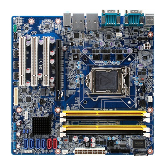
Page 20: Motherboard Layout
ERX-Q77 User’s Manual 2.3.3 Motherboard Layout 20 ERX-Q77 User’s Manual... -
Page 21: Jumper And Connector List
RJ-45 Ethernet Connector x 1 P41~42 USB 3.0 Connector x 2 LAN2_USB34 RJ-45 Ethernet Connector x 1 P41~42 USB 3.0 Connector x 2 Audio Audio Line-In , Line-Out , Mic.-In 5.1 Channel Audio I/O (3 jacks) ERX-Q77 User’s Manual 21... -
Page 22: Internal Connectors
USB Connector * 6 5 x 2 header, pitch 2.54mm LVDS1 LVDS Connector 20 x 2 wafer JBKL1 LVDS Inverter Power Connector 5 x 1 wafer, pitch 2.00mm LPT1 Print Port Connector 13 x 2 wafer, pitch 2.00mm 22 ERX-Q77 User’s Manual... -
Page 23: Central Processing Unit (Cpu)
If you purchased a separate CPU heatsink and fan assembly, make sure that you have properly applied Thermal Interface Material to the CPU heatsink or CPU before you install the heatsink and fan assembly. ERX-Q77 User’s Manual 23... -
Page 24: Installing The Cpu
Press the load lever with your thumb (A), then move it to the left (B) until it is released from the retention tab. Retention tab Load lever To prevent damage to the socket pins, do not remove the PnP cap unless you are installing a CPU. 24 ERX-Q77 User’s Manual... - Page 25 (A) until it snaps into the retention tab. The CPU fits in only one correct orientation. DO NOT force the CPU into the socket to prevent bending the connectors on the socket and damaging the CPU! ERX-Q77 User’s Manual 25...
-
Page 26: Installing The Cpu Heatsink And Fan
Motherboard hole Orient the heatsink and fan assembly such that the CPU fan cable is closest to the CPU fan connector. Make sure each fastener is oriented as shown, with the narrow groove directed outward. 26 ERX-Q77 User’s Manual... - Page 27 Do not forget to connect the fan cables to the fan connectors. Insufficient air flow inside the system may damage the motherboard components. These are not jumpers! DO NOT place jumper caps on the fan connectors. ERX-Q77 User’s Manual 27...
-
Page 28: Uninstalling The Cpu Heatsink And Fan
2. Rotate each fastener counterclockwise 3. Pull up two fasteners at a time in a diagonal sequence to disengage the heatsink and fan assembly from the motherboard. 4. Carefully remove the heatsink and fan assembly from the motherboard. 28 ERX-Q77 User’s Manual... - Page 29 ERX-Q77 User’s Manual 5. Rotate each fastener clockwise to ensure correct orientation when reinstalling. ERX-Q77 User’s Manual 29...
-
Page 30: System Memory
240-pin DDR2 DIMM. DDR3 DIMMs are notched differently to prevent installation on a DDR2 DIMM socket. The following figure illustrates the location of the sockets: 240-Pin DDR3 DIMM sockets Channel Socket DIMMA1 Channel A DIMMA2 DIMMB1 Channel B DIMMB2 30 ERX-Q77 User’s Manual... -
Page 31: Memory Configurations
2.6.3 Installing a SO-DIMM Unlock a DIMM socket by pressing the retaining clips outward. Align a DIMM on the socket such that the notch on the DIMM matches the break on the socket. ERX-Q77 User’s Manual 31... - Page 32 DDR2 DIMMs to the DDR3 DIMM socket. Make sure to unplug the power supply before adding or removing DIMMs or other system components. Failure to do so may cause severe damage to both the motherboard and the components. 32 ERX-Q77 User’s Manual...
- Page 33 2. Align a DIMM on the socket such that the notch on the DIMM matches the break on the socket. 3. Firmly insert the DIMM into the socket until the retaining clips snap back in place and the DIMM is properly seated. ERX-Q77 User’s Manual 33...
-
Page 34: Removing A Dimm
1. Simultaneously press the retaining clips downward to unlock the DIMM. 2. Remove the DIMM from the socket. Unlocked retaining clip Support the DIMM lightly with your fingers when pressing the retaining clips. The DIMM might get damaged when it flips out with extra force. 34 ERX-Q77 User’s Manual... -
Page 35: Expansion Card
1. Turn on the system and change the necessary BIOS settings, if any. See Chapter 2 for information on BIOS setup. 2. Assign an IRQ to the card if needed. Refer to the tables on the next page. 3. Install the software drivers for the expansion card. ERX-Q77 User’s Manual 35... -
Page 36: Pci Express X16 Slot
The following figure shows a graphics card installed on the PCI Express x16 slot. 2.7.4 PCI slot This motherboard supports one PCI slot that complies with the PCI specifications. The following figure shows a audio card installed on the PCI slot. 36 ERX-Q77 User’s Manual... -
Page 37: Jumper Settings And Connectors
You do not need to clear the RTC when the system hangs due to overclocking. For system failure due to overclocking, use the C.P.R. (CPU Parameter Recall) feature. Shut down and reboot the system so the BIOS can automatically reset parameter settings to default values. ERX-Q77 User’s Manual 37... -
Page 38: At/Atx Power Mode Select (Pson1)
This jumper allows you to select ATX Mode or AT mode . ATX MODE (Default) AT MODE 2.8.3 COM1 RS232/422/485 SETTING (CN2) This jumper allows you to select COM1 to support RS232/422/485 RS232 (Default) RS422 RS485 38 ERX-Q77 User’s Manual... -
Page 39: Com5 Rs232/485 Setting (Cn4)
2.8.4 COM5 RS232/485 SETTING (CN4) This jumper allows you to select COM5 to support RS232/485 RS232 (Default) RS485 2.8.5 COM3 POWER SETTING (JCOMPWR1) This jumper allows you to select COM3 to support Ring/+12V/+5V Ring (Default) +12V ERX-Q77 User’s Manual 39... -
Page 40: Lvds Backlight Power Selection (Jbklvol1)
LVDS Backlight power selection (JBKLVOL1) This jumper allows you to select LVDS backlight power type +3.3V / +5V +3.3V (Default) 2.8.7 LVDS Backlight control mode (JBKL2) This jumper allows you to select LVDS backlight control mode PWM (Default) Linear 40 ERX-Q77 User’s Manual... -
Page 41: Rear Panel Connectors
7 & 8. LAN (RJ-45) port. This port allows Gigabit connection to a Local Area Network (LAN) through a network hub. Refer to the table below for the LAN port LED indications. LAN port LED indications ERX-Q77 User’s Manual 41... - Page 42 12. Line Out port (lime). This port connects a headphone or a speaker. In 4-channel, 6-channel, and 8-channel configuration, the function of this port becomes Front Speaker Out. 13. Microphone port (pink). This port connects a microphone. 42 ERX-Q77 User’s Manual...
-
Page 43: Cpu And System Fan Connectors (Cpu_Fan, Sys_Fan, Cha_Fan)
Do not forget to connect the fan cables to the fan connectors. Insufficient air flow inside the system may damage the motherboard components. These are not jumpers! DO NOT place jumper caps on the fan connectors. ERX-Q77 User’s Manual 43... -
Page 44: System Panel (F_Panel)
Hard Disk Drive Activity LED (Pin 1-3) This 2-pin connector is for the HDD Activity LED. Connect the HDD Activity LED cable to this connector. The IDE LED lights up or flashes when data is read from or written to the HDD. 44 ERX-Q77 User’s Manual... -
Page 45: Atx Power Connectors (Eatxpwr1 & Atx12V1)
Make sure that your power supply unit (PSU) can provide at least the minimum power required by your system. See the table below for details. ERX-Q77 User’s Manual 45... -
Page 46: Serial Port Connectors (Com3, Com4, Com5)
Digital IO Connector (DIO1) This connector is for 8-bit General purpose I/O function. DIO1 1. DIO_GP0 2. DIO_GP4 3. DIO_GP1 4. DIO_GP5 5. DIO_GP2 6. DIO_GP6 7. DIO_GP3 8. DIO_GP7 9. SMB_CLK_RESUME 10. SMB_DATA_RESUME 11. GND 12. +V5_DUAL 46 ERX-Q77 User’s Manual... -
Page 47: Audio Mic.-In & Line-Out Connector (Fpaud1)
9. LINE2L 10. LINE2-JD For motherboards with the optional HD Audio feature, we recommend that you connect a high-definition front panel audio module to this connector to avail of the motherboard’s high‑ definition audio capability ERX-Q77 User’s Manual 47... -
Page 48: Digital Audio Connector (Spdif_O)
S/PDIF audio cable to this connector and the other end to the S/PDIF module. SPDIF_O 4. GND 3. SPDIF-OUT 2. NC 1. +V5 2.8.16 Amplifier Connector (JAMP1) JAMP1 1. AMP_L- 2. AMP_L+ 3. AMP_R- 4. AMP_R+ 48 ERX-Q77 User’s Manual... -
Page 49: Serial Ata Connector (Sata1~2, Sata3~6 )
Serial ATA signal cables for Serial ATA hard disk drives. SATA Connect the right-angle side of SATA signal cable to SATA device. Or you may connect the right-angle side of SATA cable to the onboard SATA port to avoid mechanical conflict with large graphics cards. ERX-Q77 User’s Manual 49... -
Page 50: Usb Connectors (Usb56, Usb78, Usb910)
3. USB- 4. USB- 5. USB+ 6. USB+ 7. GND 8. GND 10. NC Never connect a 1394 cable to the USB connectors. Doing so will damage the motherboard! The USB module is purchased separately. 50 ERX-Q77 User’s Manual... -
Page 51: Lvds Connector (Lvds1)
36. LVDS_A_CLK- 35. LVDS_B_CLK- 38. GND 37. GND 40. VDD_+12V 39. VDD_+12V 2.8.20 LCD Inverter Connector (JBKL1) The connector is for the control of internal LVDS brightness. 1. +12V 2. GND 3. BL_EN 4. Backlight 5. +5V ERX-Q77 User’s Manual 51... -
Page 52: Lpt Port Connector (Lpt1)
9. LPT_PD3 10. GND 11. LPT_PD4 12. GND 13. LPT_PD5 14. GND 15. LPT_PD6 16. GND 17. LPT_PD7 18. GND 19. LPT_ACK# 20. GND 21. LPT_BUSY 22. GND 23. LPT_PE 24. GND 25. LPT_SLCT 26. NC 52 ERX-Q77 User’s Manual... -
Page 53: Bios Setup
ERX-Q77 User’s Manual 3. BIOS Setup ERX-Q77 User’s Manual 53... -
Page 54: Introduction
The BIOS setup screens shown in this section are for reference purposes only, and may not exactly match what you see on your screen. Visit the system builder’s website to download the latest BIOS file for this motherboard 54 ERX-Q77 User’s Manual... -
Page 55: Using Setup
<F9> to load the optimal default values. While moving around through the Setup program, note that explanations appear in the Item Specific Help window located to the right of each menu. This window displays the help text for the currently highlighted field. ERX-Q77 User’s Manual 55... -
Page 56: Bios Setup
To access the menu items, press the up/down/right/left arrow key on the keyboard until the desired item is highlighted, then press [Enter] to open the specific menu. 56 ERX-Q77 User’s Manual... -
Page 57: Main Setup
Use this menu for basic system configurations, such as time, date etc. BIOS Information Displays the auto-detected BIOS information. System Date The date format is <Date>,<Month>,<Day>,<Year>. System Time The time format is <Hour>,<Minute>,<Second>. ERX-Q77 User’s Manual 57... -
Page 58: Advanced Bios Setup
The Advanced BIOS Setup screen is shown below. The sub menus are described on the following pages. Take caution when changing the settings of the Advanced menu items. Incorrect field values can cause the system to malfunction. 58 ERX-Q77 User’s Manual... -
Page 59: Pci Subsystem Setting
PCI bus. Configuration options: [32 PCI Bus Clocks] [64 PCI Bus Clocks] [96 PCI Bus Clocks] [128 PCI Bus Clocks] [160 PCI Bus Clocks] [192 PCI Bus Clocks] [224 PCI Bus Clocks] [248 PCI Bus Clocks] ERX-Q77 User’s Manual 59... -
Page 60: Acpi Settings
Enable or disable system wake on alarm even. When enabled, system will wake upon the hr/min/sec specified. Configuration options: [Disabled] [Enabled] Wake on PCIE [Enabled] Control PCIE device wake up function. Configuration options: [Disabled] [Enabled] 60 ERX-Q77 User’s Manual... -
Page 61: Trusted Computing
Control PCI device wake up function. Configuration options: [Disabled] [Enabled] 3.4.5 Trusted computing Trusted computing (TPM) settings. Configuration Security Device Support [Disable] Enable or disable TPM support. Configuration options: [Disable] [Enable] Current TPM Status Information Displays the TPM status information. ERX-Q77 User’s Manual 61... -
Page 62: Cpu Configuration
Limit CPUID Maximum [Disable] Disable for Windos XP. Configuration options: [Disabled] [Enabled] Intel Virtualization Technology [Disabled] When enable, a VMM can utilize the additional hardware capabilities provided by Vanderpool Technology. Configuration options: [Disabled] [Enabled] 62 ERX-Q77 User’s Manual... -
Page 63: Sata Configuration
ERX-Q77 User’s Manual 3.4.7 SATA Configuration SATA Controller(s) [Enabled] Enable or disable SATA device(s) Configuration options: [Disabled] [Enabled] SATA Mode Selection [IDE] Support IDE, AHCI or RAID mode Configuration options: [IDE][AHCI][RAID] ERX-Q77 User’s Manual 63... -
Page 64: Intel Txt(Lt) Configuration
ERX-Q77 User’s Manual 3.4.8 Intel TXT(LT) Configuration Display Intel Trusted Execution Technology configuration. 64 ERX-Q77 User’s Manual... -
Page 65: Pch-Fw Configuration
ERX-Q77 User’s Manual 3.4.9 PCH-FW Configuration Display management engine technology configuration. ERX-Q77 User’s Manual 65... -
Page 66: Amt Configuration
3.4.10 AMT Configuration AMT Parameters Intel AMT [Enable] Enable or disable Intel active management technology BIOS extension Configuration options: [Disabled] [Enabled] Un-configure ME [Disabled] Perform AMT/ME un-configure without password operation. Configuration options: [Disabled] [Enabled] 66 ERX-Q77 User’s Manual... -
Page 67: Usb Configuration
Display how many devices are connected. Legacy USB Support [Enabled] Enables Legacy USB support. AUTO option disables legacy support if no USB devices are connected. DISABLE option will keep USB devices available only for EFI applications. Configuration options: [Enabled] [Disabled][Auto] ERX-Q77 User’s Manual 67... -
Page 68: Second Super Io Configuration
ERX-Q77 User’s Manual 3.4.12 Second Super IO Configuration Second Super IO Chip Parameters. Super IO Configuration Super IO Chip [Fintek F81216] 68 ERX-Q77 User’s Manual... -
Page 69: Serial Port 3 Configuration
Configuration options: [Enabled] [Disabled] Device Settings [IO=3E8h; IRQ=5] Change Settings [Auto] Select an optimal setting for Super IO device Configuration options: [Auto] [IO=3E8h; IRQ=5] [IO=3F8h; IRQ=5, 10] [IO=2F8h; IRQ=5, 10] [IO=3E8h; IRQ=5, 10] [IO=2E8h; IRQ=5, 10] ERX-Q77 User’s Manual 69... -
Page 70: Serial Port 4 Configuration
Configuration options: [Enabled] [Disabled] Device Settings [IO=2E8h; IRQ=5] Change Settings [Auto] Select an optimal setting for Super IO device Configuration options: [Auto] [IO=2E8h; IRQ=5] [IO=3F8h; IRQ=5, 10] [IO=2F8h; IRQ=5, 10] [IO=3E8h; IRQ=5, 10] [IO=2E8h; IRQ=5, 10] 70 ERX-Q77 User’s Manual... -
Page 71: Serial Port 5 Configuration
Device Settings [IO=2E0h; IRQ=10] Change Settings [Auto] Select an optimal setting for Super IO device Configuration options: [Auto] [IO=2E0h; IRQ=10] [IO=3F8h; IRQ=5, 10] [IO=2F8h; IRQ=5, 10] [IO=3E8h; IRQ=5, 10] [IO=2E8h; IRQ=5, 10] [IO=2E0h; IRQ=5, 10] [IO=2F0h; IRQ=5, 10] ERX-Q77 User’s Manual 71... -
Page 72: Erx-Q77 User's Manual
ERX-Q77 User’s Manual 3.4.13 Super IO Configuration System Super IO Chip Parameters. Super IO Configuration Super IO Chip [NCT6776F] 72 ERX-Q77 User’s Manual... - Page 73 Configuration options: [Auto] [IO=3F8h; IRQ=4] [IO=3F8h; IRQ=3, 4, 5, 6, 7, 9, 10, 11, 12] [IO=2F8h; IRQ=3, 4, 5, 6, 7, 9, 10, 11, 12] [IO=3E8h; IRQ=3, 4, 5, 6, 7, 9, 10, 11, 12] [IO=2E8h; IRQ=3, 4, 5, 6, 7, 9, 10, 11, 12] ERX-Q77 User’s Manual 73...
- Page 74 Configuration options: [Auto] [IO=2F8h; IRQ=3] [IO=3F8h; IRQ=3, 4, 5, 6, 7, 9, 10, 11, 12] [IO=2F8h; IRQ=3, 4, 5, 6, 7, 9, 10, 11, 12] [IO=3E8h; IRQ=3, 4, 5, 6, 7, 9, 10, 11, 12] [IO=2E8h; IRQ=3, 4, 5, 6, 7, 9, 10, 11, 12] 74 ERX-Q77 User’s Manual...
- Page 75 Device Mode [STD Printer Mode] Change the printer port mode Configuration options: [STD Printer Mode] [SPP Mode] [EPP-1.9 and SPP Mode] [EPP-1.7 and SPP Mode] [ECP Mode] [ECP and EPP 1.9 Mode] [ECP and EPP 1.7 Mode] ERX-Q77 User’s Manual 75...
-
Page 76: Hardware Monitor
Enable or disable Watch Dog Timer Function Configuration options: [Disabled] [Enabled] Deep S5 Support [Disabled] Enable or disable Deep S5 support EuP Configuration options: [Disabled] [Enabled] 3.4.14 Hardware Monitor PC Health Status Display system health status 76 ERX-Q77 User’s Manual... - Page 77 ERX-Q77 User’s Manual 3.4.14.1 Smart Fan Smart Fan Function [Enable] Enable or disable smart fan function ERX-Q77 User’s Manual 77...
- Page 78 SYS Smart Fan Mode [Manual Mode] Set system smart fan mode Configuration options: [Manual Mode] [Thermal Cruise Mode] CPU Smart Fan Mode [Manual Mode] Set CPU smart fan mode Configuration options: [Manual Mode] [Thermal Cruise Mode] 78 ERX-Q77 User’s Manual...
-
Page 79: Option Rom Policy
Controls the execution of UEFI and Legacy storage OpROM Configuration options: [Disabled] [Enabled] Other PCI device ROM priority [UEFI OpROM] For PCI devices other than Network, mass storage or video defines which OpROM to launch Configuration options: [UEFI OpROM] [Legacy OpROM] ERX-Q77 User’s Manual 79... -
Page 80: Cpu Ppm Configuration
CPU C6 Report [Enabled] Enabled or disabled CPU C6 (ACPI C3) report to OS Configuration options: [Disabled] [Enabled] CPU C7 Report [Enabled] Enabled or disabled CPU C7 (ACPI C3) report to OS Configuration options: [Disabled] [Enabled] 80 ERX-Q77 User’s Manual... -
Page 81: Chipset
ERX-Q77 User’s Manual 3.4.17 Chipset ERX-Q77 User’s Manual 81... -
Page 82: Pch-Io Configuration
ERX-Q77 User’s Manual 3.4.18 PCH-IO Configuration Display PCH information 82 ERX-Q77 User’s Manual... -
Page 83: Usb Configuration
Control the USB EHCI (USB 2.0) functions. One EHCI controller must always be enabled. Configuration options: [Disabled] [Enabled] USB Ports Per-Port Disable Control [Disabled] Control each of the USB ports (0~13) disabling Configuration options: [Disabled] [Enabled] ERX-Q77 User’s Manual 83... -
Page 84: Pch Azalia Configuration
PCH Azalia Configuration Azalia [Auto] Control detection of the Azalia device Configuration options: [Disabled] [Enabled] [Auto] Azalia HDMI codec Port C [Enabled] Enable or disable internal HDMI codec port for Azalia Configuration options: [Disabled] [Enabled] 84 ERX-Q77 User’s Manual... -
Page 85: System Agent (Sa) Configuration
ERX-Q77 User’s Manual 3.4.19 System Agent (SA) Configuration Display system agent information ERX-Q77 User’s Manual 85... -
Page 86: Graphics Configuration
Select DVMT 5.0 pre-allocated (fixed) graphics memory size used by internal graphics device Configuration options: [32M] [64M] [96M] [128M] [160M] [192M] [224M] [256M] [288M] [320M] [352M] [384M] [416M] [448M] [480M] [512M] DVMT Total Graphic Mem [256M] 86 ERX-Q77 User’s Manual... - Page 87 [1400x1050 24bit Dual Channel] [1600x900 24bit Dual Channel] [1680x1050 24bit Dual Channel] [1600x1200 24bit Dual Channel] [1920x1080 24bit Dual Channel] [1920x1200 24bit Dual Channel] LVDS Brightness Control [255] Set LVDS brightness. The range is from 0 to 255 ERX-Q77 User’s Manual 87...
- Page 88 Control ASPM support for the PEG: Device 1 Function 0. This has no effect if PEG is not the currently active device. Configuration options: [Disabled] [Auto] [ASPM L0s] [ASPM L1] [ASPM L0sL1] Enable PEG [Auto] Enabled or disabled PEG Configuration options: [Disabled] [Enabled] [Auto] 88 ERX-Q77 User’s Manual...
- Page 89 ERX-Q77 User’s Manual .4.19.3 Memory Configuration Memory Information Display Memory Information ERX-Q77 User’s Manual 89...
-
Page 90: Boot
Number of seconds to wait for setup activation key. 65535(0xFFFF) means indefinite waiting. Bootup NumLock State [On] Select the keyboard NumLock state Configuration options: [On] [Off] Quick Boot [Disable] Enable or disable Quiet Boot option Configuration options: [Disabled] [Enabled] 90 ERX-Q77 User’s Manual... -
Page 91: Security
ERX-Q77 User’s Manual 3.4.21 Security Administrator Password Set setup Administrator Password User Password Set User Password ERX-Q77 User’s Manual 91... -
Page 92: Save & Exit
Exit system setup after saving the changes. Discard changes and Exit Exit system setup without saving the changes. Save changes and Reset Reset the system after saving the changes. Restore Defaults Restore/Load default values for all the setup option. 92 ERX-Q77 User’s Manual...
Need help?
Do you have a question about the ERX-Q77 and is the answer not in the manual?
Questions and answers