Table of Contents
Advertisement
Quick Links
Download this manual
See also:
User Manual
Advertisement
Table of Contents

Related Manuals for Avalue Technology ERX-G41


Summary of Contents for Avalue Technology ERX-G41
- Page 1 ERX-G41 ® ® Core™ 2 Quad Intel G41 LGA775 socket for Intel Micro-ATX Motherboard User’s Manual Ed – 15 November 2011 Part No: E2047RX4100R...
- Page 2 Disclaimer Avalue Technology Inc. reserves the right to make changes, without notice, to any product, including circuits and/or software described or contained in this manual in order to improve design and/or performance. Avalue Technology assumes no responsibility or liability for the...
-
Page 3: Technical Support
Avalue has come to be known. Your satisfaction is our primary concern. Here is a guide to Avalue’s customer services. To ensure you get the full benefit of our services, please follow the instructions below carefully. - Page 4 ERX-G41 and ready to give you the support you need to get the most from your Avalue’s products. In fact, most problems reported are minor and are able to be easily solved over the phone. In addition, free technical support is available from Avalue’s engineers every business day.
-
Page 5: Product Warranty
If any of Avalue’s products is defective, it will be repaired or replaced at no charge during the warranty period. For out-of-warranty repairs, you will be billed according to the cost of replacement materials, service time, and freight. -
Page 6: Table Of Contents
Architecture Overview – Block Diagram ............11 Hardware Configuration ....................12 Product Overview ..................... 13 Installation Procedure ..................14 2.2.1 Main Memory ..................15 Jumper and Connector List ................17 Setting Jumpers & Connectors ................ 19 3. Mechanical Drawing....................... 22 ERX-G41 User’s Manual... -
Page 7: Getting Started
User’s Manual 1. Getting Started 1.1 Safety Precautions Warning! Always completely disconnect the power cord from your chassis whenever you work with the hardware. Do not make connections while the power is on. Sensitive electronic components can be damaged by sudden power surges. -
Page 8: Document Amendment History
ERX-G41 1.3 Document Amendment History Revision Date Comment January Initial Release 2011 Packing list update November Company information update 2011 ERX-G41 User’s Manual... -
Page 9: Manual Objectives
We strongly recommend that you study this manual carefully before attempting to interface with ERX-G41 series or change the standard configurations. Whilst all the necessary information is available in this manual we would recommend that unless you are confident, you contact your supplier for guidance. -
Page 10: System Specifications
Support by ADD2 card LVDS+VGA, ADD2+VGA/LVDS Secondary VGA Audio RealtekR ALC888, 5.1 +2 with two independent Streaming Audio Codec Line-out, Line-in, Mic-in, SPDIF header Audio Interface Ethernet RealtekR RTL8111D GbE LAN LAN1 LAN2 RealtekR RTL8111D GbE LAN ERX-G41 User’s Manual... -
Page 11: Architecture Overview - Block Diagram
User’s Manual 1.6 Architecture Overview – Block Diagram The following block diagram shows the architecture and main components of ERX-G41. User’s Manual... -
Page 12: Hardware Configuration
ERX-G41 2. Hardware Configuration ERX-G41 User’s Manual... -
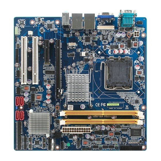
Page 13: Product Overview
User’s Manual 2.1 Product Overview User’s Manual... -
Page 14: Installation Procedure
Note: Make sure the heat sink and the CPU top surface are in total contact to avoid CPU overheating problem that would cause the system to hang or unstable ERX-G41 User’s Manual... -
Page 15: Main Memory
User’s Manual 2.2.1 Main Memory ERX-G41 provides 2 x 240 pin DDR DIMM sockets supports DDRII memories 667/800 MHz up to 4GB Make sure to unplug the power supply before adding or removing DIMMs or other system components. Failure to do so may cause severe damage to both the board and the components. - Page 16 (2) Static electricity can damage the electronic components of the computer or optional boards. Before starting these procedures, ensure that you are discharged of static electricity by touching a grounded metal object briefly. ERX-G41 User’s Manual...
-
Page 17: Jumper And Connector List
User’s Manual 2.3 Jumper and Connector List You can configure your board to match the needs of your application by setting jumpers. A jumper is the simplest kind of electric switch. It consists of two metal pins and a small metal clip (often protected by a plastic cover) that slides over the pins to connect them. - Page 18 General purpose I/O connector 10 x 2 header, pitch 2.54mm SYS_FAN1 System fan connector 3 x 1 wafer, pitch 2.54mm SPDIF_01 Digital Audio connector 4 x 1 header, pitch 2.54mm USB 45/67 USB connector 5 x 2 header, pitch 2.54mm ERX-G41 User’s Manual...
-
Page 19: Setting Jumpers & Connectors
User’s Manual 2.4 Setting Jumpers & Connectors Jumpers Label Function Note CLRTC1 Clear CMOS Normal * Clear CMOS JCOMPWR1, RI/+5V/+12V Select RI * +12V JCOMPWR2 JCOMPWR3 JCOMPWR4 CHASSIS1 Chassis Intrusion Connector JSETCOM6 Serial Port 6 in RS 232/422/485 RS232 Signal Signal RXD6 RXD485... - Page 20 ERX-G41 Connectors Label Function Note AAFP1 Front Panel Audio Connector CHA_FAN1 Chassis Fan Connector CPU_FAN1 CPU Fan Connector F_PANEL1 System Panel Connector JDIO1 Digital I/O Connector ERX-G41 User’s Manual...
- Page 21 User’s Manual SYS_FAN1 System Fan Connector SPDIF_01 Digital Audio connector USB45, USB67, USB 2.0 Connector User’s Manual...
-
Page 22: Mechanical Drawing
ERX-G41 3. Mechanical Drawing ERX-G41 User’s Manual... - Page 23 User’s Manual User’s Manual...
- Page 24 ERX-G41 ERX-G41 User’s Manual...
Need help?
Do you have a question about the ERX-G41 and is the answer not in the manual?
Questions and answers