
Related Manuals for Avalue Technology EAX-Q67


Summary of Contents for Avalue Technology EAX-Q67
- Page 1 EAX-Q67 Intel® Q67 with Core™ i7/ i5 /i3 ATX Motherboard User’s Manual Ed – 10 August 2012 Part No: E2047AQ6701R...
- Page 2 Disclaimer Avalue Technology Inc. reserves the right to make changes, without notice, to any product, including circuits and/or software described or contained in this manual in order to improve design and/or performance. Avalue Technology assumes no responsibility or liability for the...
-
Page 3: Technical Support
EAX-Q67 User’s Manual Life Support Policy Avalue Technology’s PRODUCTS ARE NOT FOR USE AS CRITICAL COMPONENTS IN LIFE SUPPORT DEVICES OR SYSTEMS WITHOUT THE PRIOR WRITTEN APPROVAL OF Avalue Technology Inc. As used herein: 1. Life support devices or systems are devices or systems which, (a) are intended for surgical... - Page 4 Avalue Technology Inc. Room 805, Building 9,No.99 Tianzhou Rd., 3F Ishiyama-Bldg, 1-6-1 Taito, Caohejing Development Area, Taito-ku, Tokyo 110-0016 Japan Xuhui District, Shanghai Tel: +81-3-5807-2321 Tel: +86-21-5169-3609 Fax:+86-21-5445-3266 Fax: +81-3-5807-2322 Information: sales.china@avalue.com.cn Information: sales.japan@avalue.com.tw Service: service@avalue.com.tw Service: service@avalue.com.tw 4 EAX-Q67 User’s Manual...
-
Page 5: Table Of Contents
Jumpers ........................32 1.7.1 Clear CMOS (JCMOS1) ......................... 32 1.7.2 AT/ATX Power Mode Select (PSON1) ....................33 Connectors ......................... 33 1.8.1 Rear panel connectors ........................... 33 1.8.2 CPU and System fan connectors (CPU_FAN, SYS_FAN,CHA_FAN) ..........34 EAX-Q67 User’s Manual 5... - Page 6 2.4.10 Super IO Configuration ........................58 2.4.11 Hardware Monitor ..........................68 Chipset ........................69 2.5.1 North Bridge ............................70 2.5.2 South Bridge ............................72 2.5.3 ME Subsystem ............................76 Boot ..........................77 Security ........................79 Save & Exit ......................... 80 6 EAX-Q67 User’s Manual...
-
Page 7: Safety Information
If you encounter technical problems with the product, contact a qualified service technician or your retailer. The symbol of the crossed out wheeled bin indicates that the product (electrical and electronic equipment) should not be placed in municipal waste. Check local regulations for disposal of electronic products. EAX-Q67 User’s Manual 7... -
Page 8: About This Guide
Visit the Avalue Taiwan website: http://www.avalue.com.tw Optional documentation Your product package may include optional documentation, such as warranty flyers, that may have been added by your dealer. These documents are not part of the standard package. 8 EAX-Q67 User’s Manual... -
Page 9: Typography
Example: <Ctrl>+<Alt>+<D> Means that you must type the command exactly as shown, Command then supply the required item or value enclosed in brackets Example: At the DOS prompt, type the command line: afudos /i[filename] afudos /iP5P800VM.ROM EAX-Q67 User’s Manual 9... -
Page 10: Packing List
EAX-Q67 User’s Manual Packing List Before you begin installing your single board, please make sure that the following materials have been shipped: 1 x EAX-Q67 ATX Main board 1 x DVD-ROM contains OS drivers 2 x COM cable ... -
Page 11: Revision History
EAX-Q67 User’s Manual Revision History Revision Revision History Date V 1.0 First release version for PCB R10 December , 2011 Modified manual descriptions and jumper’s V1.2 Aug,2012 setting EAX-Q67 User’s Manual 11... -
Page 12: Specifications Summary
Onboard HDMI 1.3, supports max resolution 1920 x 1080 (@60Hz) HDMI Audio Realtek ALC892, 5.1 Channel HD Audio Audio Codec Line-in, Line-out, Mic-in, S/PDIF, Front Audio Header Audio Interface Ethernet Intel 82579LM LAN1 Intel 82583V LAN2 12 EAX-Q67 User’s Manual... -
Page 13: Block Diagram
EAX-Q67 User’s Manual * Specifications are subject to change without notice. Block Diagram EAX-Q67 User’s Manual 13... - Page 14 EAX-Q67 User’s Manual This chapter describes the motherboard features and the new technologies it supports. Product Introduction 14 EAX-Q67 User’s Manual...
-
Page 15: Chapter 1 - Product Introduction
• DirectX® 10.1 & Open GL 3.0 let you enjoy awesome graphics performance, stunning 3D visual effect and dynamic interactivity • Memory support, integrated low voltage DDR3 memory controller • Operating system support: - Microsoft -WindRiver -Redhat EAX-Q67 User’s Manual 15... -
Page 16: Key Architecture Features
- PCI Express® x 4Gen 2 5GT/s - PCI Express® x 1Gen 2 5GT/s - PCI 2.3 interface - Six SATA ports (4 port of Gen 2.0 and 2 ports of Gen 3.0) support RAID 0,1, 5, 10 16 EAX-Q67 User’s Manual... -
Page 17: Before You Proceed
Before you install or remove any component, ensure that the ATX power supply is switched off or the power cord is detached from the power supply. Failure to do so may cause severe damage to the motherboard, peripherals, and/or components. EAX-Q67 User’s Manual 17... -
Page 18: Motherboard Overview
Place eight (8) screws into the holes indicated by circles to secure the motherboard to the chassis. Do not over tighten the screws! Doing so can damage the motherboard. Place this side towards the rear of the chassis. 18 EAX-Q67 User’s Manual... -
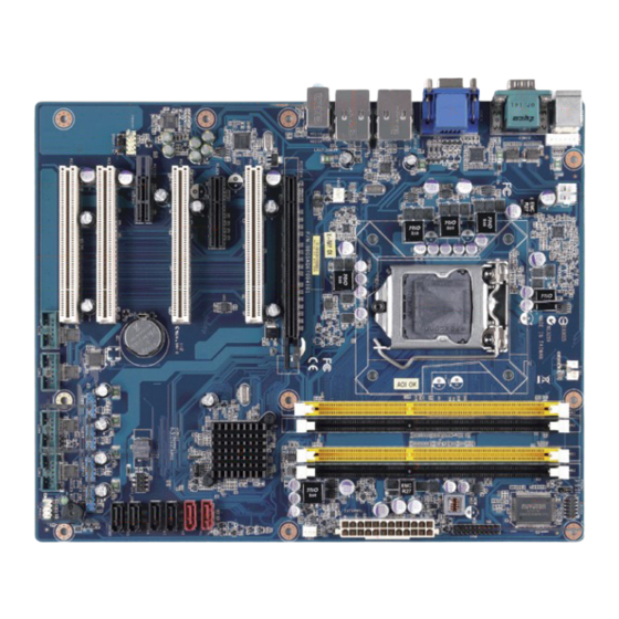
Page 19: Motherboard Layout
240-pin DDR3 DIMM Slot A1 DIMMA2 240-pin DDR3 DIMM Slot A2 DIMMB1 240-pin DDR3 DIMM Slot B1 DIMMB2 240-pin DDR3 DIMM Slot B2 PCIEX16 PCI-e x16 Slot PCIEX4 PCI-e x4 Slot PCIEX1 PCI-e x1 Slot PCI Slot EAX-Q67 User’s Manual 19... -
Page 20: Internal Connector
10 x 2 header, pitch 2.54mm SATA1, 2 SATA3.0 Data Connector 7P Male connector SATA3 ~ 6 SATA II Data Connector 7P Male connector USB56 USB78 USB Connector * 8 5 x 2 header, pitch 2.54mm USB910 USB1112 20 EAX-Q67 User’s Manual... -
Page 21: Central Processing Unit (Cpu)
If you purchased a separate CPU heatsink and fan assembly, make sure that you have properly applied Thermal Interface Material to the CPU heatsink or CPU before you install the heatsink and fan assembly. EAX-Q67 User’s Manual 21... -
Page 22: Installing The Cpu
2. Press the load lever with your thumb (A), then move it to the left (B) until it is released from the retention tab. To prevent damage to the socket pins, do not remove the PnP cap unless you are installing a CPU. 22 EAX-Q67 User’s Manual... - Page 23 (A) until it snaps into the retention tab. The CPU fits in only one correct orientation. DO NOT force the CPU into the socket to prevent bending the connectors on the socket and damaging the CPU! EAX-Q67 User’s Manual 23...
-
Page 24: Installing The Cpu Heatsink And Fan
CPU heatsink or CPU before you install the heatsink and fan assembly. To install the CPU heatsink and fan: 1. Place the heatsink on top of the installed CPU, making sure that the four fasteners match the holes on the motherboard. 24 EAX-Q67 User’s Manual... - Page 25 Do not forget to connect the fan cables to the fan connectors. Insufficient air flow inside the system may damage the motherboard components. These are not jumpers! DO NOT place jumper caps on the fan connectors. EAX-Q67 User’s Manual 25...
-
Page 26: Uninstalling The Cpu Heatsink And Fan
2. Rotate each fastener counterclockwise 2. Pull up two fasteners at a time in a diagonal sequence to disengage the heatsink and fan assembly from the motherboard. 4. Carefully remove the heatsink and fan assembly from the motherboard. 26 EAX-Q67 User’s Manual... -
Page 27: System Memory
240-pin DDR2 DIMM. DDR3 DIMMs are notched differently to prevent installation on a DDR2 DIMM socket. The following figure illustrates the location of the sockets: 240-Pin DDR3 DIMM sockets Channel Socket DIMMA1 Channel A DIMMA2 DIMMB1 Channel B DIMMB2 EAX-Q67 User’s Manual 27... -
Page 28: Memory Configurations
1.5.3 Installing a DIMM Unlock a DIMM socket by pressing the retaining clips outward. Align a DIMM on the socket such that the notch on the DIMM matches the break on the socket. 28 EAX-Q67 User’s Manual... -
Page 29: Removing A Dimm
1. Simultaneously press the retaining clips downward to unlock the DIMM. 2. Remove the DIMM from the socket. Support the DIMM lightly with your fingers when pressing the retaining clips. The DIMM might get damaged when it flips out with extra force. EAX-Q67 User’s Manual 29... -
Page 30: Expansion Card
3. Install the software drivers for the expansion card. 1.6.3 PCI Express x16 slot This motherboard supports one PCI Express x16 slot that complies with the PCI Express specifications. The following figure shows a graphics card installed on the PCI Express x16 slot. 30 EAX-Q67 User’s Manual... -
Page 31: Pciex4 Raid Card
The following figure shows a LAN card installed on the PCI Express x 1 slot. 1.6.6 PCI slot This motherboard supports 4 PCI slots that complies with the PCI specifications. The following figure shows a audio card installed on the PCI slot. EAX-Q67 User’s Manual 31... -
Page 32: Jumpers
You do not need to clear the RTC when the system hangs due to overclocking. For system failure due to overclocking, use the C.P.R. (CPU Parameter Recall) feature. Shut down and reboot the system so the BIOS can automatically reset parameter settings to default values. 32 EAX-Q67 User’s Manual... -
Page 33: At/Atx Power Mode Select (Pson1)
Refer to the table below for the LAN port LED indications. LAN port LED indications SPEED LED ACT / LINK LED Status Description Status Description 10Mbps connection No link Orange 100Mbps connection Green Link Green 1Gbps connection Blinking Data activity EAX-Q67 User’s Manual 33... -
Page 34: Cpu And System Fan Connectors (Cpu_Fan, Sys_Fan,Cha_Fan)
Do not forget to connect the fan cables to the fan connectors. Insufficient air flow inside the system may damage the motherboard components. These are not jumpers! DO NOT place jumper caps on the fan connectors. 34 EAX-Q67 User’s Manual... -
Page 35: Eax-Q67 User's Manual 35
Hard Disk Drive Activity LED (Pin 1-3 HDLED) This 2-pin connector is for the HDD Activity LED. Connect the HDD Activity LED cable to this connector. The IDE LED lights up or flashes when data is read from or written to the HDD. EAX-Q67 User’s Manual 35... -
Page 36: Atx Power Connectors (Eatxpwr1)
This connector is for a serial (COM) port. Connect the serial port module cable to this connector, then install the module to a slot opening at the back of the system chassis. COM3 , COM4 , COM5 , COM6 36 EAX-Q67 User’s Manual... -
Page 37: Digital Io Connector (Jdio1)
This connector is for a chassis-mounted front panel audio I/O module that supports either HD Audio or legacy AC ‘97 (optional) audio standard. FPAUD1 1.8.8 Internal KB/MS connector (KBMS2) This connector is for internal KB/MS. KBMS2 EAX-Q67 User’s Manual 37... -
Page 38: Digital Audio Connector (Spdif_Out)
12.GND 13.NC 14.NC 15.+V3.3_DUAL 16.PCI_SERIRQ 17.GND 18.GND 19.LPCPD# 20.NC 1.8.11 Serial ATA 3.0 Connector (SATA1, SATA2) These connectors support SATA 3.0 and are for the Serial ATA signal cables for Serial ATA hard disk drives. SATA1、SATA2 38 EAX-Q67 User’s Manual... -
Page 39: Serial Ata Ii Connector (Sata3 , Sata4 , Sata5, Sata6 )
These USB connectors comply with USB 2.0 specification that supports up to 480 Mbps connection speed. USB56, USB78, USB910, USB1112 Never connect a 1394 cable to the USB connectors. Doing so will damage the motherboard! The USB module is purchased separately. EAX-Q67 User’s Manual 39... - Page 40 EAX-Q67 User’s Manual This chapter tells how to change the system settings through the BIOS Setup menus. Detailed descriptions of the BIOS parameters are also provided. 40 EAX-Q67 User’s Manual...
-
Page 41: Chapter 2 - Bios Setup
The BIOS setup screens shown in this section are for reference purposes only, and may not exactly match what you see on your screen. Visit the system builder’s website to download the latest BIOS file for this motherboard EAX-Q67 User’s Manual 41... -
Page 42: Legend Box
<F9> to load the optimal default values. While moving around through the Setup program, note that explanations appear in the Item Specific Help window located to the right of each menu. This window displays the help text for the currently highlighted field. 42 EAX-Q67 User’s Manual... -
Page 43: Bios Menu Screen
To access the menu items, press the up/down/right/left arrow key on the keyboard until the desired item is highlighted, then press [Enter] to open the specific menu. EAX-Q67 User’s Manual 43... -
Page 44: Main Setup
Displays the auto-detected BIOS information. Memory Information Displays the auto-detected system memory System Date The date format is <Date>,<Month>,<Day>,<Year>. System Time The time format is <Hour>,<Minute>,<Second>. Access Level Displays the accessory information. 44 EAX-Q67 User’s Manual... -
Page 45: Advanced Bios Setup
The PCI PnP menu items allow you to change the advanced settings for PCI/PnP devices. The menu includes setting IRQ and DMA channel resources for either PCI/PnP or legacy ISA devices, and setting the memory size block for legacy ISA devices. EAX-Q67 User’s Manual 45... - Page 46 Configuration options: [32 PCI Bus Clocks] [64 PCI Bus Clocks] [96 PCI Bus Clocks] [128 PCI Bus Clocks] [160 PCI Bus Clocks] [192 PCI Bus Clocks] [224 PCI Bus Clocks] [248 PCI Bus Clocks] VGA Palette Snoop [Disable] Enables or disables VGA palette registers snooping. Configuration options: [Disabled] [Enabled] 46 EAX-Q67 User’s Manual...
- Page 47 Configuration options: [Disabled] [Enabled] SPERR# Generation [Disable] Enables or disables PCI devices to Generate SPERR#. Configuration options: [Disabled] [Enabled] 2.4.1 2 PCI Express Device Settings PCI Express Device Register Settings PCI Express Link Register Settings EAX-Q67 User’s Manual 47...
- Page 48 EAX-Q67 User’s Manual 2.4.1 3 PCI Express GEN2 Device Settings PCI Express GEN2 Device Register Settings PCI Express GEN2 Link Register Settings 48 EAX-Q67 User’s Manual...
-
Page 49: Acpi Settings
Configuration options: [Suspend Disable][S1 (CPU Stop Clock)] [S3 (suspend to RAM )] Resume On RTC Alarm [Disable] Enable or disable system wake on alarm even. When enabled, system will wake upon the hr/min/sec specified. Configuration options: [Disabled] [Enabled] EAX-Q67 User’s Manual 49... -
Page 50: Trusted Computing
EAX-Q67 User’s Manual 2.4.3 Trusted computing Trusted computing (TPM) settings. TPM configuration TPM SUPPORT [Disabled] Enable or disable TPM support. Configuration options: [Disabled] [Enabled] Current TPM Status Information Displays the TPM status information [No TPM Hardware] 50 EAX-Q67 User’s Manual... -
Page 51: Cpu Configuration
Select the numbers of cores in each processor package. Configuration options: [All] [1] [2] [3] [4] [5] [6] [7] It depends on each CPU type. Limit CPUID Maximum [Disable] Disable for Windos XP. Configuration options: [Disabled] [Enabled] EAX-Q67 User’s Manual 51... - Page 52 Configuration options: [Disabled] [Enabled] Power Technology [Energy efficient] Enable the power management features. Configuration options: [Disabled] [Energy efficient] [Enabled] Local x2APIC [Disable] Enable Local x2APIC. Some OSes do not support this. Configuration options: [Disabled] [Enabled] 52 EAX-Q67 User’s Manual...
-
Page 53: Sata Configuration
Support IDE, AHCI or RAID mode Configuration options: [Disable][IDE Mode][AHCI Mode][RAID Mode] Serial-ATA Controller 0 [Compatible] Enabled/Disabled Serial-ATA Controller 0 Configuration options: [Disable] [Enhanced] [Compatible] Serial-ATA Controller 1 [Enhanced] Enabled/Disabled Serial-ATA Controller 1 Configuration options: [Disable] [Enhanced] [Compatible] EAX-Q67 User’s Manual 53... -
Page 54: Intel Igd Swsci Opregion
Select DVMT/FIXED Mode Memory size used by Internal Graphic Device. Configuration options: [128MB][512MB][Maximum] IGD – Boot Type [VBIOS Default] Select the video Device which will be activated during POST. This has no effect if external graphics present. Configuration options: [VBIOS Default][CRT][HDMI][DisplayPort] 54 EAX-Q67 User’s Manual... -
Page 55: Intel Txt(Lt) Configuration
EAX-Q67 User’s Manual 2.4.7 Intel TXT(LT) Configuration Display Intel Trusted Execution Technology configuration. EAX-Q67 User’s Manual 55... -
Page 56: Usb Configuration
EHCI driver. Configuration options: [Disabled] [Enabled] Port 60/64 Emulation [Enabled] Enables I/O port 60h/64h emulation support. This should be enabled for complete USB keyboard legacy support for non-USB aware OSes. Configuration options: [Disabled] [Enabled] 56 EAX-Q67 User’s Manual... -
Page 57: Amt Configuration
Configuration options: [Disabled] [Enabled] Unconfigure AMT/ME [Disable] Perform AMT/ME unconfigure without password operation. Configuration options: [Disabled] [Enabled] WatchDog Timer [Disable] Enable/Disable WatchDog Timer. Configuration options: [Disabled] [Enabled] When ‘Enabled’, OS and BIOS WatchDog Timers can be set. EAX-Q67 User’s Manual 57... -
Page 58: Super Io Configuration
EAX-Q67 User’s Manual 2.4.10 Super IO Configuration System Super IO Chip Parameters. Super IO Configuration Super IO Chip [NCT6776F] 58 EAX-Q67 User’s Manual... - Page 59 Configuration options: [Auto] [IO=3F8h; IRQ=4] [IO=3F8h; IRQ=3, 4, 5, 6, 7, 9. 10, 11, 12] [IO=2F8h; IRQ=3, 4, 5, 6, 7, 9. 10, 11, 12] [IO=3E8h; IRQ=3, 4, 5, 6, 7, 9. 10, 11, 12] [IO=2E8h; IRQ=3, 4, 5, 6, 7, 9. 10, 11, 12] EAX-Q67 User’s Manual 59...
- Page 60 Configuration options: [Auto] [IO=2F8h; IRQ=3] [IO=3F8h; IRQ=3, 4, 5, 6, 7, 9. 10, 11, 12] [IO=2F8h; IRQ=3, 4, 5, 6, 7, 9. 10, 11, 12] [IO=3E8h; IRQ=3, 4, 5, 6, 7, 9. 10, 11, 12] [IO=2E8h; IRQ=3, 4, 5, 6, 7, 9. 10, 11, 12] 60 EAX-Q67 User’s Manual...
- Page 61 Select an optimal setting for Super IO device. Configuration options: [Auto] [IO=C80h; IRQ=5] [IO=C80h; IRQ=5, 7, 9. 10, 11] [IO=C88h; IRQ=5, 7, 9. 10, 11] [IO=C90h; IRQ=5, 7, 9. 10, 11] [IO=C98h; IRQ=5, 7, 9. 10, 11] EAX-Q67 User’s Manual 61...
- Page 62 Select an optimal setting for Super IO device. Configuration options: [Auto] [IO=C88h; IRQ=5] [IO=C80h; IRQ=5, 7, 9. 10, 11] [IO=C88h; IRQ=5, 7, 9. 10, 11] [IO=C90h; IRQ=5, 7, 9. 10, 11] [IO=C98h; IRQ=5, 7, 9. 10, 11] 62 EAX-Q67 User’s Manual...
- Page 63 Select an optimal setting for Super IO device. Configuration options: [Auto] [IO=C90h; IRQ=5] [IO=C80h; IRQ=5, 7, 9. 10, 11] [IO=C88h; IRQ=5, 7, 9. 10, 11] [IO=C90h; IRQ=5, 7, 9. 10, 11] [IO=C98h; IRQ=5, 7, 9. 10, 11] EAX-Q67 User’s Manual 63...
- Page 64 Select an optimal setting for Super IO device. Configuration options: [Auto] [IO=C98h; IRQ=5] [IO=C80h; IRQ=5, 7, 9. 10, 11] [IO=C88h; IRQ=5, 7, 9. 10, 11] [IO=C90h; IRQ=5, 7, 9. 10, 11] [IO=C98h; IRQ=5, 7, 9. 10, 11] 64 EAX-Q67 User’s Manual...
- Page 65 Chassis Fan Mode [Manual Mode] Select Chassis Fan mode Configuration options: [Manual Mode] [Thermal Cruise Mode][SNART FAN IV Mode] Resume on PS2 KB [Disabled] Enable or Disable Resume on PS2 KB Function Configuration options: [Disabled] [Enabled] EAX-Q67 User’s Manual 65...
- Page 66 Watch Dog Timer [Disabled] Enable or Disable Watch Dog Timer Function Configuration options: [Disabled] [Enabled] 2.4.10.8 Digital I/O Configuration Digital I/O Configuration Digital I/O Pin 0 [Input] Configure Digital I/O Pin Configuration options: [Input][Output High][Output Low] 66 EAX-Q67 User’s Manual...
- Page 67 Configure Digital I/O Pin Configuration options: [Input][Output High][Output Low] Digital I/O Pin 6 [Input] Configure Digital I/O Pin Configuration options: [Input][Output High][Output Low] Digital I/O Pin 7 [Input] Configure Digital I/O Pin Configuration options: [Input][Output High][Output Low] EAX-Q67 User’s Manual 67...
-
Page 68: Hardware Monitor
F] [75 C/167 F] ACPI Shutdown Temperature [Disable] Enabled or Disabled CPU warning temperature Function Configuration options: [Disable] [70 C/158 F] [75 C/167 F] [80 C/176 F] [85 C/185] [90 C/194 F] [95 C/205 F] 68 EAX-Q67 User’s Manual... -
Page 69: Chipset
EAX-Q67 User’s Manual 2.5 Chipset EAX-Q67 User’s Manual 69... -
Page 70: North Bridge
Configuration options: [Disabled] [Enabled] VT-d [Disable] Set VT-d Enable or Disable Configuration options: [Disabled] [Enabled] Internal Graphic Adapter [PEG/IGD] Select which graphics controller to use as the primary boot device. Configuration options: [IGD][PCI/IGD][PCI/PEG][PEG/IGD] [PEG/PCI] 70 EAX-Q67 User’s Manual... - Page 71 Enable/Disable PCI Express Port Configuration options: [Disabled] [Enabled][Auto] PEG Force Gen1 PCI Express Port PEG Force Gen1 Configuration options: [Disabled] [Enabled][Auto] Detect Non-Compliance Detect Non-Compliance PCI Express device in PEG Configuration options: [Disabled] [Enabled][Auto] EAX-Q67 User’s Manual 71...
-
Page 72: South Bridge
LAN1 Controller [Enable] Enable/Disable LAN1 Controller Configuration options: [Disabled] [Enabled] LAN1 Option-ROM [Disable] Enable/Disable LAN1 boot option for legacy network devices. Configuration options: [Disabled] [Enabled] Wake on LAN1 from S5 [Disable] Configuration options: [Disabled] [Enabled] 72 EAX-Q67 User’s Manual... - Page 73 Configuration options: [Disabled] [Enabled] Azalia internal HDMI codec [Enable] Enable/Disable Azalia internal HDMI codec Configuration options: [Disabled] [Enabled] High Precision Event Timer Configuration High Precision Timer [Enable] Enable/Disable the High Precision Timer Configuration options: [Disabled] [Enabled] EAX-Q67 User’s Manual 73...
- Page 74 Enable/Disable PCI Express Port 7 Configuration options: [Disabled] [Enabled][Auto] PCIe Sub Decode [Disable] Enable/Disable PCIe Sub Decode Port. ( This option is available when subtractive decode agent Enable (PCHTrap9[14] = ‘1b’) Configuration options: [Disabled] [Enabled][Auto] 74 EAX-Q67 User’s Manual...
- Page 75 EAX-Q67 User’s Manual 2.5.2.2 USB Configuration EHCI controller 1 [Enabled] Enable/Disable USB 2.0(EHCI) support Configuration options: [Disabled] [Enabled] EHCI controller 2 [Enabled] Enable/Disable USB 2.0(EHCI) support Configuration options: [Disabled] [Enabled] EAX-Q67 User’s Manual 75...
-
Page 76: Me Subsystem
Configuration options: [Disabled] [Enabled] ME Temporary Disable [Disabled] Configuration options: [Disabled] [Enabled] End of Post Message [Enabled] Configuration options: [Disabled] [Enabled] Execute MEBx [Normal] Configuration options: [Normal] [Hidden Ctrl + P][Enter MEBx Setup] 76 EAX-Q67 User’s Manual... -
Page 77: Boot
Number of seconds to wait for setup activation key. 65535(0xFFFF) means indefinite waiting. Bootup NumLock State [On] Select the keyboard NumLock state Configuration options: [On] [Off] Quick Boot [Disable] Configuration options: [Disable] [Enable] CSM16 Module Version [07.64] Display CSM16 Module Version. EAX-Q67 User’s Manual 77... - Page 78 Configuration options: [Force BIOS] [Keep Current] Interrupt 19 Capture [Disable] Enabled : Allow option ROMs to trap Int19. Configuration options: [Disabled][Enabled] Boot option priorities [Built-in EFI Shell] Select the system boot order. Configuration options: [Built-in EFI Shell][Disabled] 78 EAX-Q67 User’s Manual...
-
Page 79: Security
EAX-Q67 User’s Manual 2.7 Security Administrator Password Set setup Administrator Password User Password Set User Password EAX-Q67 User’s Manual 79... -
Page 80: Save & Exit
Reset the system without saving the changes. Save Option Save changes Save changes done so for to any of the setup option. Discard changes Discard changes done so for to any of the setup option. 80 EAX-Q67 User’s Manual... - Page 81 Restore/Load default values for all the setup option. Save as User Defaults Save the changes done so far as User Defaults. Restore User Defaults Restore the user defaults to all the setup options BOOT Override Built-in EFI Shell EAX-Q67 User’s Manual 81...
Need help?
Do you have a question about the EAX-Q67 and is the answer not in the manual?
Questions and answers