
Related Manuals for Avalue Technology ERX-H110KP


Summary of Contents for Avalue Technology ERX-H110KP
- Page 1 ERX-H110KP Intel® 6/7th Generation Core™ Processor Micro ATX Motherboard With Intel® H110 Express Chipset User’s Manual Ed – 16 October 2017 Part No. E2047ERKP00R...
- Page 2 Disclaimer Avalue Technology Inc. reserves the right to make changes, without notice, to any product, including circuits and/or software described or contained in this manual in order to improve design and/or performance. Avalue Technology assumes no responsibility or liability for the...
- Page 3 Applications that are described in this manual are for illustration purposes only. Avalue Technology Inc. makes no representation or warranty that such application will be suitable for the specified use without further testing or modification.
- Page 4 A product returned without proof of the purchase date is not eligible for warranty service. Write the RMA number visibly on the outside of the package and ship it prepaid to your dealer. 4 ERX-H110KP User’s Manual...
-
Page 5: Table Of Contents
CPU fan connector (CPUFAN1) ....................28 2.3.21 System fan connector 1 (SYSFAN1) ..................29 2.3.22 System fan connector 2 (SYSFAN3) ..................29 2.3.23 PS/2 keyboard & mouse header (JKBMS1) ................30 2.3.24 SMBus connector (JSMB1) ......................30 ERX-H110KP User’s Manual... - Page 6 3.6.2.7.1 COM1 ............................ 52 3.6.2.8 Intel TXT Configuration ......................53 3.6.2.9 Network Stack Configuration ....................54 3.6.2.10 CSM Configuration ........................ 55 3.6.2.11 USB Configuration ......................... 57 3.6.3 Chipset............................58 3.6.3.1 System Agent (SA) Configuration ..................58 6 ERX-H110KP User’s Manual...
- Page 7 Install Chipset Driver ....................69 Install VGA Driver ....................70 Install ME Driver ...................... 72 Install Audio Driver (For Realtek ALC892 HD Audio) ..........73 Install LAN Driver ....................74 Install IRST Driver ....................76 5. Mechanical Drawing ....................78 ERX-H110KP User’s Manual...
-
Page 8: Getting Started
1.2 Packing List Before you begin installing your single board, please make sure that the following materials have been shipped: 1 x ERX-H110KP motherboard 2 x SATA cable 1 x I/O Shield ... -
Page 9: Document Amendment History
User’s Manual 1.3 Document Amendment History Revision Date Comment October 2017 Avalue Initial Release ERX-H110KP User’s Manual... -
Page 10: Manual Objectives
We strongly recommend that you study this manual carefully before attempting to set up ERX-H110KP or change the standard configurations. Whilst all the necessary information is available in this manual we would recommend that unless you are confident, you contact your supplier for guidance. -
Page 11: System Specifications
1 x full size Mini PCI-e Slot with SIM card slot 1 x M.2 2230 Type A Slot Display Chipset Intel® H110 Express chipset VGA: 2048 x 1536@50 Hz Resolution HDMI: 4096 x 2160@24 Hz, 2560 x 1600@60 Hz ERX-H110KP User’s Manual 11... - Page 12 1 x 4 pin, pitch wafer 2.00mm connector for 6W x 2 Speaker 1 x 1 x 4 pin, pitch 2.54mm connector for S/PDIF 1 x 1 x 3pin, pitch 2.54mm connector for COMS Clear 1 x horizontal type battery connector 12 ERX-H110KP User’s Manual...
- Page 13 0% ~ 90% relative humidity, non-condensing Humidity Size (L x W) 243.84mm x 243.84mm Weight 0.60 kg Note: 1. The Windows 7 & Windows 8 must be Setup USB 3.0 driver. 2. Specifications are subject to change without notice. ERX-H110KP User’s Manual 13...
-
Page 14: Architecture Overview-Block Diagram
ERX-H110KP User’s Manual 1.6 Architecture Overview—Block Diagram The following block diagram shows the architecture and main components of ERX-H110KP. 14 ERX-H110KP User’s Manual... -
Page 15: Hardware Configuration
User’s Manual 2. Hardware Configuration ERX-H110KP User’s Manual 15... -
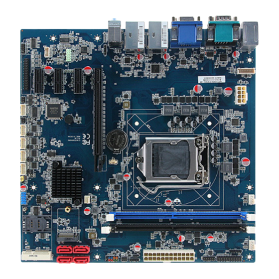
Page 16: Product Overview
ERX-H110KP User’s Manual 2.1 Product Overview 16 ERX-H110KP User’s Manual... -
Page 17: Jumper And Connector List
System fan connector 1 4 x 1 wafer, pitch 2.54mm 3 x 1 wafer, pitch 2.54mm SYSFAN3 System fan connector 2 JFP1 Front panel setting connector 5 x 2 header, pitch 2.54 mm DIMM1/2 288-pin DDR4 DIMM socket ERX-H110KP User’s Manual 17... - Page 18 Auxiliary panel connector 10 x 2 header, pitch 2.54 mm NGFF1 M.2 2230 Type A Slot 13 x 2 header, pitch 2.54 mm JLPT1 LPT connector 5 x 1 header, pitch 2.54 mm JSMB1 SMBus connector 18 ERX-H110KP User’s Manual...
-
Page 19: Setting Jumpers & Connectors
Serial port 1/2 pin9 signal select (JRI1/2) Ring* +12V JRI2 JRI1 * Default Note: Max Current 1A. 2.3.2 Serial port 3/4/5/6 pin9 signal select (JRI3/4/5/6) Ring* +12V JRI6 JRI5 JRI4 JRI3 * Default Note: Max Current 1A. ERX-H110KP User’s Manual 19... -
Page 20: At/Atx Power Mode Select (Jatatx1)
ERX-H110KP User’s Manual 2.3.3 AT/ATX Power Mode Select (JATATX1) ATX* * Default 2.3.4 Clear CMOS (JCMOS1) Protect* Clear CMOS * Default Note: Clear CMOS must work on G3 (AC-OFF) state. 20 ERX-H110KP User’s Manual... -
Page 21: Me Update (For Flash Bios Use) (Jme_En1)
ME update (For Flash BIOS use) (JME_EN1) Open* Short * Default 2.3.6 General purpose I/O connector (JDIO1) Signal PIN PIN Signal SMB_CLK_9555 10 SMB_DATA_9555 Note: Max current 1A change as below Provide max current 1A for +5V. ERX-H110KP User’s Manual 21... -
Page 22: Serial Port 2 Connector (Jcom2A)
ERX-H110KP User’s Manual 2.3.7 Serial port 2 connector (JCOM2A) Signal PIN PIN Signal 2.3.8 COM2 RS485/422 connector (JCOM2B) Signal PIN PIN Signal 422RX+ 485TX+ 422RX- 485TX- Note: Max Current 1A. 22 ERX-H110KP User’s Manual... -
Page 23: Serial Port 3/4/5/6 Connector (Jcom3/4/5/6)
User’s Manual 2.3.9 Serial port 3/4/5/6 connector (JCOM3/4/5/6) JCOM6 JCOM5 JCOM4 JCOM3 Signal PIN PIN Signal 2.3.10 Sony/Philips Digital Interface (JSPDIF1) Signal SPDIF_O ERX-H110KP User’s Manual 23... -
Page 24: Atx Power Connector (Atxpwr1)
ERX-H110KP User’s Manual 2.3.11 ATX Power connector (ATXPWR1) Signal Signal +3.3V +3.3V +3.3V -12V ATX_PSON# ATX_PWRGD +V5SB +12V +12V +3.3V 2.3.12 ATX 12V power connector (ATX12V1) Signal Signal +12V +12V +12V +12V 24 ERX-H110KP User’s Manual... -
Page 25: Usb 2.0 Connector (Jusb4)
User’s Manual 2.3.13 USB 2.0 connector (JUSB4) Signal Signal USB_R_DP5 USB_R_DP6 USB_R_DN5 USB_R_DN6 USBVCC_56 USBVCC56 2.3.14 Battery connector (JBAT1) Signal RTC_VBAT_1 Note: This connector is reserved for change battery. ERX-H110KP User’s Manual 25... -
Page 26: Front Audio Connector (Jaudio1)
2.3.15.1 Signal Description –Audio connector (JAUDIO1) Signal Signal Description LINE2_JD AUDIO IN (LINE_RIN/LIN)sense pin MIC2_JD MIC IN (MIC_RIN/LIN) sense pin 2.3.16 LPC connector (JLPC1) Signal PIN PIN Signal LPC_SERIRQ_R LPC_CLK LPC_AD3_R LPC_FRAME#_R LPC_AD2_R BUF_PLT_RST# LPC_AD1_R +3.3V LPC_AD0_R 26 ERX-H110KP User’s Manual... -
Page 27: Spi Connector (Jspi1)
User’s Manual 2.3.17 SPI connector (JSPI1) Signal PIN PIN Signal SSPI_HOLD#0 SSPI_SI_R SSPI_SO_R SSPI_SCLK_R SSPI_CS0#_R +3.3V 2.3.18 Amplifier connector (JSPK1) Signal SPK_L+ SPK_L- SPK_R+ SPK_R- Note: Support 6W x 2 speakers. Mapping Connector PHR-4. ERX-H110KP User’s Manual 27... -
Page 28: Front Panel Setting Connector (Jfp1)
ERX-H110KP User’s Manual 2.3.19 Front panel setting connector (JFP1) Signal PIN PIN Signal HDD_LED+ PWR_LED+ HDD_LED- PWE_LED- RSET_BTN# PWRBTN# 2.3.20 CPU fan connector (CPUFAN1) Signal +12V CPUFANIN CPUFANOUT 28 ERX-H110KP User’s Manual... -
Page 29: System Fan Connector 1 (Sysfan1)
User’s Manual 2.3.21 System fan connector 1 (SYSFAN1) Signal +12V SYSFANIN1 SYSFANOUT1 2.3.22 System fan connector 2 (SYSFAN3) Signal +12V SYS_FAN_IN_2 ERX-H110KP User’s Manual 29... -
Page 30: Ps/2 Keyboard & Mouse Header (Jkbms1)
ERX-H110KP User’s Manual 2.3.23 PS/2 keyboard & mouse header (JKBMS1) Signal KBCK KBDT MSDT MSCK 2.3.24 SMBus connector (JSMB1) Signal SMB_CLK_MAIN SMB_DATA_MAIN SMB_ALERT#_MAIN +3.3V 30 ERX-H110KP User’s Manual... -
Page 31: Auxiliary Panel Connector (Jauxp1)
User’s Manual 2.3.25 Auxiliary panel connector (JAUXP1) Signal PIN PIN Signal SMB_CLK_MAIN CASEOPEN# ERROR_LED SMB_DATA_MAIN ERROR_LED# FRONT_LAN1_ACT 13 FRONT_LAN1_LINK100# 16 FRONT_LAN1_LINK1000# FRONT_LAN2_ACT 17 FRONT_LAN2_LINK100# 20 FRONT_LAN2_LINK1000# 2.3.26 PC Buzzer header (JBZ1) Signal SIO_BEEP ERX-H110KP User’s Manual 31... -
Page 32: Lpt Connector (Jlpt1)
Linked Green connection Note: 1Gbps Blinking Data activity Orange This port allows Gigabit connection to a Local Area connection Network (LAN) through a network hub. Refer to the table below for the LAN port LED indications. 32 ERX-H110KP User’s Manual... -
Page 33: Bios Setup
User’s Manual 3.BIOS Setup ERX-H110KP User’s Manual 33... -
Page 34: Introduction
If you do not press the keys at the correct time and the system does not boot, an error message will be displayed and you will again be asked to. Press F1 to Continue, DEL to enter SETUP 34 ERX-H110KP User’s Manual... -
Page 35: Using Setup
Note: Some of the navigation keys differ from one screen to another. To Display a Sub Menu Use the arrow keys to move the cursor to the sub menu you want. Then press <Enter>. A “” pointer marks all sub menus. ERX-H110KP User’s Manual 35... -
Page 36: Getting Help
BIOS Vendor and your systems manufacturer to provide the absolute maximum performance and reliability. Even a seemingly small change to the chipset setup has the potential for causing you to use the override. 36 ERX-H110KP User’s Manual... -
Page 37: Bios Setup
<Enter> to accept and enter the sub-menu. 3.6.1 Main Menu This section allows you to record some basic hardware configurations in your computer and set the system clock. ERX-H110KP User’s Manual 37... -
Page 38: System Language
Note: The BIOS setup screens shown in this chapter are for reference purposes only, and may not exactly match what you see on your screen. Visit the Avalue website (www.avalue.com.tw) to download the latest product and BIOS information. 38 ERX-H110KP User’s Manual... -
Page 39: Advanced Menu
This section allows you to configure your CPU and other system devices for basic operation through the following sub-menus. 3.6.2.1 CPU Configuration Use the CPU configuration menu to view detailed CPU specification and configure the CPU. ERX-H110KP User’s Manual 39... -
Page 40: Cpu - Power Management Control
CPU to go to C states when it’s not Enabled[Default] 100285503928tilized. Enable/Disable C1E. When enabled, CPU will Disabled, Enhanced C-states switch to minimum speed when all cores enter Enabled[Default] C-State. Disabled, C-State Auto Demotion Configure C-State Auto Demotion. 40 ERX-H110KP User’s Manual... -
Page 41: Pch-Fw Configuration
Enabled 0: Disable; 1: Enable; <b>2: Auto</b> (Auto: Auto[Default] Enabled for Skylake; Disabled for Kabylake). 3.6.2.2 PCH-FW Configuration Item Options Description Disabled, When Disabled ME will be put into ME ME State Enabled[Default] Temporarily Disabled Mode. ERX-H110KP User’s Manual 41... -
Page 42: Firmware Update Configuration
ERX-H110KP User’s Manual 3.6.2.2.1 Firmware Update Configuration Item Option Description Disabled[Default], ME FW Image Re-Flash Enable/Disable Me FW Image Re-Flash function. Enabled 3.6.2.3 ACPI Settings 42 ERX-H110KP User’s Manual... -
Page 43: S5 Rtc Wake Settings
Wake Up by Ring signal from S3(Sleep), S4(Hibernate) and Enabled[Default], S5(Soft Off) states. Enable/Disable USB Power delivery in S3 Disabled USB Standby Power Delivery (Sleep), S4 (Hibernate) and S5 (Soft Off) Enabled[Default], States. 3.6.2.4 S5 RTC Wake Settings ERX-H110KP User’s Manual 43... - Page 44 Wake up day of week Monday-Friday of month. Monday-Friday only. Monday-Saturday Monday-Saturday[Default] only. Select 0-23 For example enter 3 for 3am and 15 for Wake up hour 0-23 3pm. Wake up minute 0-59 0-59. Wake up second 0-59 0-59. 44 ERX-H110KP User’s Manual...
-
Page 45: Super Io Configuration
+ Increase minute(s). Wake up minute increase 1-5. 3.6.2.5 Super IO Configuration You can use this item to set up or change the Super IO configuration for serial ports. Please refer to 3.6.2.5.1~ 3.6.2.5.7 for more information. ERX-H110KP User’s Manual 45... -
Page 46: Serial Port 1 Configuration
Serial Port 6 Configuration Set Parameters of Serial Port 6 (COMF). Parallel Port Configuration Set Parameters of Parallel Port (LPT/LPTE). 3.6.2.5.1 Serial Port 1 Configuration Item Option Description Disabled Serial Port Enable or Disable Serial Port (COM). Enabled[Default], 46 ERX-H110KP User’s Manual... -
Page 47: Serial Port 2 Configuration
3.6.2.5.2 Serial Port 2 Configuration Item Option Description Disabled Serial Port Enable or Disable Serial Port (COM). Enabled[Default], RS232[Default] UART 232 422 485 RS422 Set COM Port as RS232, RS422 or RS485 mode. RS485 3.6.2.5.3 Serial Port 3 Configuration ERX-H110KP User’s Manual 47... -
Page 48: Serial Port 4 Configuration
Item Option Description Disabled Serial Port Enable or Disable Serial Port (COM). Enabled[Default], 3.6.2.5.4 Serial Port 4 Configuration Item Option Description Disabled Serial Port Enable or Disable Serial Port (COM). Enabled[Default], 3.6.2.5.5 Serial Port 5 Configuration 48 ERX-H110KP User’s Manual... -
Page 49: Serial Port 6 Configuration
User’s Manual Item Option Description Disabled Serial Port Enable or Disable Serial Port (COM). Enabled[Default], 3.6.2.5.6 Serial Port 6 Configuration Item Option Description Disabled Serial Port Enable or Disable Serial Port (COM). Enabled[Default], 3.6.2.5.7 Parallel Port Configuration ERX-H110KP User’s Manual 49... -
Page 50: Nct6106D H/W Monitor
Parallel Port Enable or Disable Serial Port (LPT/LPTE). Enabled[Default], STD Printer Mode[Default] SPP Mode Device Mode Change the Printer Port mode. EPP-1.9 and SPP Mode EPP-1.7 and SPP Mode 3.6.2.6 NCT6106D H/W Monitor 3.6.2.6.1 Smart Fan Configuration 50 ERX-H110KP User’s Manual... -
Page 51: Serial Port Console Redirection
CPU Fan manual output duty: 0 to 255. Manual Smart Fan Mode Selection: Manual Mode (No SYSFAN1 Mode SmartFan IV[Default], Smart Fan), SmartFan IV™ Mode. 3.6.2.7 Serial Port Console Redirection Item Options Description Disabled[Default], Console Redirection Console Redirection Enable or Disable. Enabled ERX-H110KP User’s Manual 51... -
Page 52: Com1
Stop bits indicate the end of a serial data packet. (A start bit indicates the beginning). 1[Default] Stop Bits The standard setting is 1 stop bit. Communication with slow devices may require more than 1 stop bit. 52 ERX-H110KP User’s Manual... -
Page 53: Intel Txt Configuration
Recorder Mode Enabled sent. This is to capture Terminal data. Disabled[Default] Enables or disables extended terminal Resolution 100x31 Enabled resolution. VT100[Default] LINUX XTERMR6 Putty KeyPad Select FunctionKey and KeyPad on Putty. ESCN VT400 3.6.2.8 Intel TXT Configuration ERX-H110KP User’s Manual 53... -
Page 54: Network Stack Configuration
Enabled IPv6 HTTP boot support will not be available. PXE boot wait time Wait time to press ESC key to abort the PXE boot. Media detect count Number of times presence of media will be checked. 54 ERX-H110KP User’s Manual... -
Page 55: Csm Configuration
Controls the execution of UEFI and Legacy Storage UEFI Storage OpROM. Legacy[Default] Do not launch Determines OpROM execution policy for devices Other PCI devices UEFI other than Network, Storage, or Video. Legacy[Default] If enable CSM Support: ERX-H110KP User’s Manual 55... - Page 56 Legacy[Default] Do not launch Controls the execution of UEFI and Legacy Storage UEFI Storage OpROM. Legacy[Default] Do not launch Determines OpROM execution policy for devices Other PCI devices UEFI other than Network, Storage, or Video. Legacy[Default] 56 ERX-H110KP User’s Manual...
-
Page 57: Usb Configuration
Mass storage device emulation type. ‘AUTO’ Floppy enumerates devices according to their media format. Mass Storage Devices Forced FDD Optical drives are emulated as ‘CDROM’, drives with Hard Disk no media will be emulated according to a drive type. CD-ROM ERX-H110KP User’s Manual 57... -
Page 58: Chipset
ERX-H110KP User’s Manual 3.6.3 Chipset 3.6.3.1 System Agent (SA) Configuration Item Option Description Enabled[Default] VT-d VT-d capability. Disabled 58 ERX-H110KP User’s Manual... -
Page 59: Graphics Configuration
User’s Manual 3.6.3.1.1 Graphics Configuration Item Option Description Auto[Default] Select which of IGFX/PEG/PCI Graphics device IGFX Primary Display should be Primary Display Or select SG for Switchable Gfx. 3.6.3.1.2 DMI/OPI Configuration ERX-H110KP User’s Manual 59... -
Page 60: Peg Port Configuration
Auto[Default] Auto[Default] Gen1 Max Link Speed Configure PEG 0:1:0 Max Speed. Gen2 Gen3 Enabled: PCIe ASPM will be programmed Disabled[Default] Program PCIe ASPM after OpROM after OpROM. Disabled: PCIe ASPM will be Enabled programmed before OpROM. 60 ERX-H110KP User’s Manual... -
Page 61: Memory Configuration
User’s Manual 3.6.3.1.3.1 PEG Port Feature Configuration Item Option Description Disabled[Default] Detect Non-Compliance PCI Express Device Detect Non-Compliance Device Enabled, in PEG. 3.6.3.1.4 Memory Configuration ERX-H110KP User’s Manual 61... -
Page 62: Pch-Io Configuration
ERX-H110KP User’s Manual 3.6.3.2 PCH-IO Configuration Item Option Description Disabled Enable or disable OnBoard PCH LAN PHY LAN PHY Controller Enabled[Default] Controller. 3.6.3.2.1 HD Audio Configuration 62 ERX-H110KP User’s Manual... -
Page 63: Sata And Rst Configuration
HAD will be unconditionally disabled Enabled = HAD will HD Audio Enabled be unconditionally enabled Auto = HAD will be enabled if Auto[Default], present, disabled otherwise. 20 dB 26 dB[Default] Amplifier Gain Select Amplifier Gain(dB). 32 dB 36 dB 3.6.3.2.2 SATA And RST Configuration ERX-H110KP User’s Manual 63... -
Page 64: Security
Hard Disk Drive[Default], Identify the SATA port is connected to Solid SATA Device Type Solid State Drive State Drive or Hard Disk Drive. 3.6.4 Security Administrator Password Set setup Administrator Password User Password Set User Password 64 ERX-H110KP User’s Manual... -
Page 65: Secure Boot Menu
User mode with enrolled Platform Key(PK) 2.CSM Enabled function is disabled. Secure Boot mode selector. ‘Custom’ Mode enables Standard Secure Boot Mode users to change Image Execution policy and manage Custom[Default] Secure Boot Keys. 3.6.4.1.1 Key Management ERX-H110KP User’s Manual 65... -
Page 66: Boot
Enables or disables boot with initialization of a Disabled[Default] Fast Boot minimal set of devices required to launch active Enabled boot option. Has no effect for BBS boot options. Boot Option #1 Set the system boot order. 66 ERX-H110KP User’s Manual... -
Page 67: Save And Exit
This option restores all BIOS settings to the factory default. This option is useful if the controller exhibits unpredictable behavior due to an incorrect or inappropriate BIOS setting. 3.6.6.4 Launch EFI Shell from filesystem device Attempts to Launch EFI Shell application (Shellx64.efi) from one of the available filesystem devices. ERX-H110KP User’s Manual 67... -
Page 68: Drivers Installation
ERX-H110KP User’s Manual 4. Drivers Installation Note: Installation procedures and screen shots in this section are for your reference and may not be exactly the same as shown on your screen. 68 ERX-H110KP User’s Manual... -
Page 69: Install Chipset Driver
Windows 10 operation system. If the warning message appears while the installation process, click Continue to go on. Step 3. Click Install. Step1. Click Next. Step 4. Installing. Step 2. Click Accept. Step 5. Complete setup. ERX-H110KP User’s Manual 69... -
Page 70: Install Vga Driver
Windows 10 operation system. Step 3. Click Next. Step 1. Click Next to continue installation. Step 4. Click Next. Step 2. Step 5. Click Next. Click Yes to accept license agreement. 70 ERX-H110KP User’s Manual... - Page 71 User’s Manual Step 6. Click Finish to complete setup. ERX-H110KP User’s Manual 71...
-
Page 72: Install Me Driver
Windows 10 operation system. Step 3. Click Next Step 4. Installing. Step 1. Click Next to continue setup. Step 5. Click Finish to complete the setup Step 2. Click Next. 72 ERX-H110KP User’s Manual... -
Page 73: Install Audio Driver (For Realtek Alc892 Hd Audio)
If the warning message appears while the installation Step 3. Click Next. process, click Continue to go on. Step 4. Installing. Step1. Click Next to Install. Step 5. Click Finish to complete the setup Step2. Click Next. ERX-H110KP User’s Manual 73... -
Page 74: Install Lan Driver
Note: The installation procedures and screen shots in this section are based on Windows 10 operation system. Step 3. Click Next. Step 1. Click Install Drivers and Step 4. Click Next. Software. Step 2. Click Next. Step 5. Click Install. 74 ERX-H110KP User’s Manual... - Page 75 User’s Manual Step 6. Installing. Step 7. Click Finish to complete setup. ERX-H110KP User’s Manual 75...
-
Page 76: Install Irst Driver
Note: The installation procedures and screen shots in this section are based on Windows 10 operation system. Step 3. Click Next. Step 1. Click Next to continue installation. Step 4. Click Next. Step 2. Click Next. Step 5. Click Next. 76 ERX-H110KP User’s Manual... - Page 77 User’s Manual Step 6. Click Next. Step 7. Click Install. Step 8. Click Finish to complete setup. ERX-H110KP User’s Manual 77...
-
Page 78: Mechanical Drawing
ERX-H110KP User’s Manual 5. Mechanical Drawing 78 ERX-H110KP User’s Manual... - Page 79 User’s Manual Unit: mm ERX-H110KP User’s Manual 79...
- Page 80 ERX-H110KP User’s Manual Unit: mm 80 ERX-H110KP User’s Manual...
Need help?
Do you have a question about the ERX-H110KP and is the answer not in the manual?
Questions and answers