
Related Manuals for Avalue Technology ERX-B75


Summary of Contents for Avalue Technology ERX-B75
- Page 1 ERX-B75 Intel® B75 Express Chipset Micro ATX Motherboard User’s Manual Ed – 09 October 2013 Part No. E2047B75R00R...
- Page 2 Disclaimer Avalue Technology Inc. reserves the right to make changes, without notice, to any product, including circuits and/or software described or contained in this manual in order to improve design and/or performance. Avalue Technology assumes no responsibility or liability for the...
-
Page 3: Technical Support
Avalue has come to be known. Your satisfaction is our primary concern. Here is a guide to Avalue’s customer services. To ensure you get the full benefit of our services, please follow the instructions below carefully. -
Page 4: Table Of Contents
Starting Setup ....................25 Using Setup ....................26 Getting Help ....................27 In Case of Problems ..................27 BIOS setup ....................28 3.6.1 Main Menu .................... 28 3.6.1.1 System Language ................28 3.6.1.2 System Date .................. 28 4 ERX-B75 User’s Manual... - Page 5 Install VGA Driver ..................49 Install LAN Driver (For Realtek 8111E Gigabit Ethernet) ......51 Install Audio Driver (For Realtek ALC661 HD Audio) ........52 Install USB3.0 Driver ..................53 Install ME Driver ................... 54 5. Mechanical Drawing ....................55 ERX-B75 User’s Manual 5...
-
Page 6: Getting Started
Before you begin installing your single board, please make sure that the following materials have been shipped: Quick Installation Guide X 1 Driver/Utility CD X 1 Serial ATA Signal Cable X 2 IO Shield X 1 Motherboard X 1 6 ERX-B75 User’s Manual... -
Page 7: Document Amendment History
ERX-B75 User’s Manual 1.3 Document Amendment History Revision Date Comment October 2013 Avalue Initial Release ERX-B75 User’s Manual 7... -
Page 8: Manual Objectives
We strongly recommend that you study this manual carefully before attempting to set up ERX-B75 series or change the standard configurations. Whilst all the necessary information is available in this manual we would recommend that unless you are confident, you contact your supplier for guidance. -
Page 9: Specifications
1 x 1 x 4 pin, pitch 2.54mm connector for Speaker Buzzer 1 x 2 x 12 pin ATX power connector 1 x 2 x 2 pin ATX 12V power connector Display ERX-B75 User’s Manual 9... - Page 10 ACPI 3.0 Compliant Operating Temp. 0°C ~60°C Storage Temp. -40°C ~75°C Operating 0%~90% relative humidity, non-condensing Humidity Size (L x W) 9.26" x 7.67" (235.1 mm x 194.9 mm) Weight 0.40 kg 10 ERX-B75 User’s Manual...
-
Page 11: Architecture Overview-Block Diagram
ERX-B75 User’s Manual 1.6 Architecture Overview—Block Diagram The following block diagram shows the architecture and main components of ERX-B75. ERX-B75 User’s Manual 11... -
Page 12: Hardware Configuration
ERX-B75 User’s Manual 2. Hardware Configuration 12 ERX-B75 User’s Manual... -
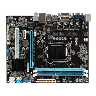
Page 13: Product Overview
ERX-B75 User’s Manual 2.1 Product Overview ERX-B75 User’s Manual 13... -
Page 14: Installation Procedure
6. Enter the BIOS setup by pressing the delete key during boot up. Use the "Save & Exit \ Restore Defaults" feature. 7. If TFT panel display is to be utilized, make sure the panel voltage is correctly set before connecting the display cable and turning on the power. 14 ERX-B75 User’s Manual... -
Page 15: Jumper And Connector List
1 x 2 header, pitch 2.54 mm Connectors Label Function Note FPANEL1 Front Panel Switches 2 x 5 header, pitch 2.54 mm PCIE 1 : PCI-e x 16 PCIE1~2 PCIE 2 : PCI-e x 1 PCI1 PCI slot HDMI1 HDMI connector ERX-B75 User’s Manual 15... - Page 16 DDR3 SDRAM DIMM socket VGA connector F_AUDIO Front Panel Audio Connection Header 2 x 5 header, pitch 2.54 mm Audio connector AUDIO1 Sony/Philips Digital Interface 1 x 3 header, pitch 2.54 mm JSPDIF Keyboard & Mouse 16 ERX-B75 User’s Manual...
-
Page 17: Setting Jumpers & Connectors
ERX-B75 User’s Manual 2.4 Setting Jumpers & Connectors 2.4.1 Clear CMOS (JBAT1) Normal* Clear CMOS Define Open Normal Short Clear CMOS * Default 2.4.2 Keyboard power select jumper (JKB1) Disabled* Enabled Define Disabled Enabled * Default ERX-B75 User’s Manual 17... -
Page 18: Me Update (For Flash Bios Use) (Jme)
ERX-B75 User’s Manual 2.4.3 ME update (For Flash BIOS use) (JME) Open* Short * Default 2.4.4 Front Panel Switches (FPANEL1) Signal PIN PIN Signal +HD_LED +P_LED -HD_LED -P_LED PWR_ON -PWR_ON 18 ERX-B75 User’s Manual... -
Page 19: Sony/Philips Digital Interface (Jspdif)
ERX-B75 User’s Manual 2.4.5 Sony/Philips Digital Interface (JSPDIF) Signal 2.4.6 Front Panel Audio Connection Header (F_AUDIO) Signal Signal PORT1L PORT1R PRESENCE# PORT2R SENSE1_RETURN SENSE_SEND PORT2L SENSE2_RETURN ERX-B75 User’s Manual 19... -
Page 20: Usb Port Headers - Usb2.0 (Fusb1)
USB Port Headers - USB2.0 (FUSB1) Signal PIN PIN Signal DATA - DATA - DATA + DATA + USB Port Headers – USB3.0 (FUSB3) 2.4.8 Signal PIN PIN Signal SSRX- SSRX- SSRX+ SSRX+ SSTX- SSTX- SSTX+ SSTX+ 20 ERX-B75 User’s Manual... -
Page 21: Atx +12V Power Connector (Atxpwr)
ERX-B75 User’s Manual 2.4.9 ATX +12V Power connector (ATXPWR) Signal PIN PIN Signal +12V +12V 2.4.10 ATX Power connector (ATXPWR1) Signal PIN PIN Signal +3.3V +12V +12V 5VSB PWRGD PS-ON +3.3V -12V +3.3V +3.3V ERX-B75 User’s Manual 21... -
Page 22: Serial Port 1 Connector (Jcom1)
ERX-B75 User’s Manual 2.4.11 Serial port 1 connector (JCOM1) Signal PIN PIN Signal 2.4.12 Speaker connector (SPEAK1) Signal INTSPL+ INTSPR- 22 ERX-B75 User’s Manual... -
Page 23: System Fan Connector (Sfan1)
ERX-B75 User’s Manual 2.4.13 System Fan connector (SFAN1) Signal +12V Ground 2.4.14 CPU Fan connector (CFAN1) Signal Ground +12V Control ERX-B75 User’s Manual 23... -
Page 24: Bios Setup
ERX-B75 User’s Manual 3.BIOS Setup 24 ERX-B75 User’s Manual... -
Page 25: Introduction
If you do not press the keys at the correct time and the system does not boot, an error message will be displayed and you will again be asked to. Press DEL to enter setup, F11 to popup menu ERX-B75 User’s Manual 25... -
Page 26: Using Setup
Note: Some of the navigation keys differ from one screen to another. To Display a Sub Menu Use the arrow keys to move the cursor to the sub menu you want. Then press <Enter>. A “” pointer marks all sub menus. 26 ERX-B75 User’s Manual... -
Page 27: Getting Help
AMI and your systems manufacturer to provide the absolute maximum performance and reliability. Even a seemingly small change to the chipset setup has the potential for causing you to use the override. ERX-B75 User’s Manual 27... -
Page 28: Bios Setup
Note: BIOS setup screens shown in this chapter are for reference only, and may not exactly match what you see on your screen. Visit the Avalue website (www.avalue.com.tw) to download the latest product and BIOS information. 28 ERX-B75 User’s Manual... -
Page 29: Advanced Bios Settings
This section allows you to configure your CPU and other system devices for basic operation through the following sub-menus. 3.6.2.1 ACPI Settings Item Options Description Enable ACPI Auto Disabled Enable or Disable BIOS ACPI Auto Enabled[Default] Configuration. Configuration Enable Hibernation Disabled Enable or Disable System ability to Hibernate ERX-B75 User’s Manual 29... -
Page 30: Onboard Device Configuration
Launch Storage OpROM policy Enabled Storage OpROM. Disabled HD Audio Controller Control of the Azalia audio. Enabled[Default] Disabled Enable or disable internal HDMI codec for Azalia Internal HDMI Codec Enabled[Default] Azalia. Disabled USB Controller Control of USB ports. Enabled[Default] 30 ERX-B75 User’s Manual... -
Page 31: Cpu Configuration
Enable/Disable CPU C1E state. Enabled[Default] Disabled[Default] Enable/Disable CPU C3/6/7(ACPI C2/3/3) report to CPU C3/6/7 Report Enabled All[Default] Number of cores to enable in each processor Active Processor Cores package. Disabled[Default] Disabled for Windows XP. Limit CPUID Maximum Enabled ERX-B75 User’s Manual 31... -
Page 32: Intel® Rapid Start Technology
3.6.2.4 Intel® Rapid Start Technology 3.6.2.5 PCH-FW Configuration Item Options Description None[Default] MEBx Type MEBx Type. MiniMEBx Disabled[Default] MDES BIOS Status Code Enable/Disable MDES BIOS Status Code. Enabled Firmware Update Configure Management Engine Technology Parameters. Configuration 32 ERX-B75 User’s Manual... -
Page 33: Usb Configuration
ERX-B75 User’s Manual 3.6.2.5.1 Firmware Update Configuration Item Options Description Disabled[Default] Enable/Disable Me FW Image Re-Flash function. Me FW Image Re-Flash Enabled 3.6.2.6 USB Configuration ERX-B75 User’s Manual 33... -
Page 34: Advanced Power Management
Generic STORAGE format. Optical drives are emulated as ‘CDROm’, Forced FDD DEVICE 9407 Hard Disk drives with no media will be emulated according to CD-ROM a drive type. 3.6.2.7 Advanced Power Management 34 ERX-B75 User’s Manual... -
Page 35: Super Io Configuration
Enable or disable System wake on alarm event. Enabled Wakeup By RTC When enabled, System will wake on the Disabled[Default] hr::min::sec specified. 3.6.2.8 Super IO Configuration Item Description Serial Port 0 Configuration Set Parameters of Serial Port 0 (COMA). ERX-B75 User’s Manual 35... -
Page 36: Hw Monitor
Auto[Default] IO=3F8h; IRQ=4; IO=3F8h; IRQ=3,4,5,6,7,9,10,11,12; Select an optimal setting for Change Settings IO=2F8h; IRQ=3,4,5,6,7,9,10,11,12; Super IO device. IO=3E8h; IRQ=3,4,5,6,7,9,10,11,12; IO=2E8h; IRQ=3,4,5,6,7,9,10,11,12; 3.6.2.9 HW Monitor The H/W Monitor shows the operating temperature, fan speeds and system voltages. 36 ERX-B75 User’s Manual... -
Page 37: Chipset
Mode: Set fan speed manual. CPUFan Control Smart-Fan Smart-Fan: Hardware control fan speed automatically. Full[Default] High Fan Speed Set Fan Speed. Middle 3.6.3 Chipset Item Description PCH Parameters. South Bridge North Bridge System Agent (SA) Parameters. ERX-B75 User’s Manual 37... -
Page 38: South Bridge
EHCI. If disabled, port is routed to EHCI. If Enabled[Default] HS port is routed to xHCI, the corresponfing Switchable SS port is enabled. Disabled Enable or disable xHCI Maximum Primary xHCI Streams Enabled[Default] Stream Array Size. 38 ERX-B75 User’s Manual... -
Page 39: North Bridge
(Fixed) Graphics Memory size used by [288M] [320M] [352M] [384M] [416M] the Internal Graphics Device. [448M] [480M] [512M] [1024M] [128M] Select DVMT 5.0 Total Graphics [256M] Memory size used by the Internal DVMT Total Gfx Mem Graphics Device. [MAX] [Default] ERX-B75 User’s Manual 39... -
Page 40: Boot Settings
Auto: If the 1 boot HDD is GPT then Auto[Default] enable UEFI boot options, otherwise UEFI Boot Disabled disable. Enabled: Enable all UEFI boot Enabled options. Disabled: Disabled all UEFI boot options. 40 ERX-B75 User’s Manual... -
Page 41: Security
If only the User's password is set, then this is a power on password and must be entered to boot or enter the BIOS setup program. In the BIOS setup program, the User will have Administrator rights. By default, no password is specified. ERX-B75 User’s Manual 41... -
Page 42: Performance Settings
Item Options Description 0-31[Default] Non Turbo Ratio Override. Non Turbo Ratio Override IGFX Core Current Max (1/8 Amp) 0-400[Default] IGFX Core Current Max (1/8 Amp). Disabled Enhanced Intel Speed Step Technology. Enhanced Intel Speed Step Enabled[Default] 42 ERX-B75 User’s Manual... -
Page 43: North Bridge Configuration
The selection of Performance Memory Manual Performance Memory Profiles Profiles which impacts memory sizing XMP Profile 1 behavior. XMP Profile 2 0-21[Default] Graphics Core Ratio Limit. Graphics Core Ratio Limit Graphics Voltage (1/256) Graphics Voltage (1/256). ERX-B75 User’s Manual 43... -
Page 44: Voltage Configuration
ERX-B75 User’s Manual 3.6.6.3 Voltage Configuration Item Options Description Set memory voltage. The unit is mV. Memory Voltage Control (IC) 1300-2100 Range:1300-2100mV. 3.6.6 Save & Exit 44 ERX-B75 User’s Manual... -
Page 45: Save Changes And Exit
The setup program then exits and reboots the controller. 3.6.6.5 Save Changes Save Changes done so far to any of the setup options. 3.6.6.6 Discard Changes Discard Changes done so far to any of the setup options. ERX-B75 User’s Manual 45... -
Page 46: Restore Defaults
This option saves a copy of the current BIOS settings as the User Defaults. This option is useful for preserving custom BIOS setup configurations. 3.6.6.9 Restore User Defaults This option restores all BIOS settings to the user defaults. This option is useful for restoring previously preserved custom BIOS setup configurations. 46 ERX-B75 User’s Manual... -
Page 47: Drivers Installation
ERX-B75 User’s Manual 4. Drivers Installation Note: Installation procedures and screen shots in this section are for your reference and may not be exactly the same as shown on your screen. ERX-B75 User’s Manual 47... -
Page 48: Install Chipset Driver
4.1 Install Chipset Driver Insert the Supporting DVD-ROM to DVD-ROM drive, click on “start” icon and it should show the index page of Avalue’s products automatically. If not, locate the folder HTML and choose the product from the targeted folder. -
Page 49: Install Vga Driver
4.2 Install VGA Driver Insert the Supporting DVD-ROM to DVD-ROM drive, click on “start” icon and it should show the index page of Avalue’s products automatically. If not, locate the folder HTML and choose the product from the targeted folder. - Page 50 ERX-B75 User’s Manual Step 7. Select Finish to complete Installation. 50 ERX-B75 User’s Manual...
-
Page 51: Install Lan Driver (For Realtek 8111E Gigabit Ethernet)
4.3 Install LAN Driver (For Realtek 8111E Gigabit Ethernet) Insert the Supporting DVD-ROM to DVD-ROM drive, and it should show the index page of Avalue’s products automatically. If not, locate Index.htm and choose the product from the menu left, or... -
Page 52: Install Audio Driver (For Realtek Alc661 Hd Audio)
4.4 Install Audio Driver (For Realtek ALC661 HD Audio) Insert the Supporting DVD-ROM to DVD-ROM drive, and it should show the index page of Avalue’s products automatically. If not, locate Index.htm and choose the product from the menu left, or link to \Driver_Audio\Realtek\ALC661\ERX-B75_Audio. -
Page 53: Install Usb3.0 Driver
4.5 Install USB3.0 Driver Insert the Supporting DVD-ROM to DVD-ROM drive, click on “start” icon and it should show the index page of Avalue’s products automatically. If not, locate the folder HTML and choose the product from the targeted folder. -
Page 54: Install Me Driver
4.6 Install ME Driver Insert the Supporting DVD-ROM to DVD-ROM drive, click on “start” icon and it should show the index page of Avalue’s products automatically. If not, locate the folder HTML and choose the product from the targeted folder. -
Page 55: Mechanical Drawing
ERX-B75 User’s Manual 5. Mechanical Drawing ERX-B75 User’s Manual 55... - Page 56 ERX-B75 User’s Manual Unit: mm 56 ERX-B75 User’s Manual...
Need help?
Do you have a question about the ERX-B75 and is the answer not in the manual?
Questions and answers