Table of Contents
Advertisement
Quick Links
Advertisement
Table of Contents

Related Manuals for Avalue Technology ENX-US15WP


Summary of Contents for Avalue Technology ENX-US15WP
- Page 1 ENX-US15WP Intel® Atom™ Processor Nano ITX Motherboard User’s Manual Ver. 1.04...
-
Page 2: Table Of Contents
ENX-US15WP Contents Safety Information ......................4 Safety Declaration ......................5 Technical Support ......................5 Conventions Used in This Guide ..................5 Packing List ........................6 Revision History .......................7 Specifications Summary....................8 Block Diagram.........................11 Production Introduction ....................13 Before you Proceed ....................13 Motherboard Overview....................14 1.2.1 Placement Direction ........................14 1.2.2... - Page 3 Integrated Peripherals ........................43 2.2.5 PnP/PCI Configurations ......................... 48 2.2.6 PC Health Status..........................50 2.2.7 Load Setup Defaults........................51 2.2.8 Set Supervisor Password ....................... 52 2.2.9 Set User Password......................... 53 2.2.10 Save and Exit Setup ........................54 2.2.11 Exit Without Saving........................55 ENX-US15WP...
-
Page 4: Safety Information
ENX-US15WP Safety Information Electrical safety To prevent electrical shock hazard, disconnect the power cable from the electrical outlet before relocating the system. When adding or removing devices to or from the system, ensure that the power cables for the devices are unplugged before the signal cables are connected. If possible, disconnect all power cables from the existing system before you add a device. -
Page 5: Safety Declaration
CAUTION: Information to prevent damage to the components when trying to complete a task. IMPORTANT: Instructions that you MUST follow to complete a task. NOTE: Tips and additional information to help you complete a task. ENX-US15WP... -
Page 6: Packing List
ENX-US15WP Packing List Before you begin installing your single board, please make sure that the following materials have been shipped: 1 x ENX-US15WP Nano ITX Main board 1 x CD-ROM contains the followings: • User’s Manual in PDF file •... -
Page 7: Revision History
Corrections of pin header pitch at Page 16 September 28, 2009 V1.02 Correction of RJ45 LED status at Page 23 December 18, 2009 V1.03 Adjust Connectors direction of Pin#1 January 4, 2010 V1.04 Add internal 2 COM port header May 1, 2010 ENX-US15WP... -
Page 8: Specifications Summary
ENX-US15WP Specifications Summary Intel® Atom™ processor Z510P 1.1GHz/Z530P 1.6GHz (400/533 MT/s MHz FSB) Intel® System Controller Hub US15WP Chipset 1 x 200-pin SODIMM 2 GB DDR2 400/533 org.x16 SDRAM Memory 1 x VGA (By Chrontel CH7317), 1 x LVDS Display Realtek ALC 888 7.1 Channel High Definition Audio Codec... - Page 9 1 x USB connectors support additional 2 USB ports 1 x 6-pin ATX Power connector 1 x COM port w/ power pin header 1 x LVDS connector Internal I/O 1 x Chassis FAN connector 1 x GPIO connector 1 x PATA interface 1 x Audio Line in ENX-US15WP...
- Page 10 ENX-US15WP Specifications Summary Mechanical & Environmental Power Requirement ATX Power Power Type 0-60℃ (32 ~ 104 ) ℉ Operating Temperature 0%~90% relative humidity, non-condensing Operating Humidity 4.72" x 4.72" (120 mm x 120 mm) Size (L x W) 0.3 lbs (0.14Kg) Weight * Specifications are subject to change without notice.
-
Page 11: Block Diagram
User’s Manual Block Diagram ENX-US15WP... - Page 12 ENX-US15WP This chapter describes the main board features and the new technologies it supports. Product Product introduction introduction...
-
Page 13: Production Introduction
Before you install or remove any component, ensure that the ATX power supply is switched off or the power cord is detached from the power supply. Failure to do so may cause severe damage to the motherboard, peripherals, and/or components. ENX-US15WP... -
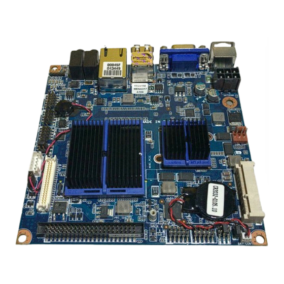
Page 14: Motherboard Overview
ENX-US15WP 1.2 Motherboard Overview Before you install the motherboard, study the configuration of your chassis to ensure that the motherboard fits into it. Refer to the chassis documentation before installing the motherboard. Make sure to unplug the power cord before installing or removing the motherboard. -
Page 15: Motherboard Layout
User’s Manual 1.3 Motherboard Layout ENX-US15WP... -
Page 16: Layout Content List
ENX-US15WP 1.3.1 Layout Content List Slots Label Function Note Page Compact Flash Card (Rear side) MINI_PCIE Mini PCI-e Slot SO_DIMM 200-pin DDR2 SODIMM slot (Rear side) Jumpers Label Function Note Page CLRTC Clear CMOS 3 x 1 header, pitch 2.54mm... -
Page 17: System Memory
A DDR2 module has the same physical dimensions as a DDR DIMM but has a 200-pin footprint compared to the 184-pin DDR DIMM. DDR2 DIMMs are notched differently to prevent installation on a DDR DIMM socket. The following figure illustrates the location of the sockets: ENX-US15WP... -
Page 18: Memory Configurations
ENX-US15WP 1.4.2 Memory Configurations You can install 256MB, 512MB, 1GB and 2GB DDR2 SDRAM DIMMs into the SODIMM sockets using the memory configurations in this section. Installing DDR2 DIMM other than the recommended configurations may cause memory sizing error or system boot failure. -
Page 19: Installing A Ddr2 Dimm
A DDR2 DIMM is keyed with a notch so that it fits in only one direction. DO NOT force a DIMM into a socket to avoid damaging the DIMM. The DDR2 DIMM sockets do not support DDR DIMMs. DO NOT install DDR DIMMs to the DDR2 DIMM socket. ENX-US15WP... -
Page 20: Removing A Ddr2 Dimm
ENX-US15WP 1.4.4 Removing a DDR2 DIMM Press the two ejector tabs on the slot outward simultaneously, and then pull out the DIMM module. Support the DIMM lightly with your fingers when pressing the ejector tabs. The DIMM might get damaged when it flips out with extra force. -
Page 21: Jumpers
Hold down the <Del> key during the boot process and enter BIOS setup to re-enter data. Except when clearing the CMOS, never remove the cap on CLRTC jumper default position. Removing the cap will cause system boot failure! Normal (Default) Clear CMOS ENX-US15WP... -
Page 22: Com1 Ri/+5V/+12V Select (Jcompwr1)
ENX-US15WP 1.5.2 COM1 RI/+5V/+12V Select (JCOMPWR1) 1.5.3 COM2 RI/+5V/+12V Select (JCOMPWR2) RI (Default) +12V... -
Page 23: Connectors
1Gbps connection GREEN Data activity MIC_IN Microphone port This port connects a microphone. LINE_OUT Line-Out port (Lime) This port connects a headphone or a speaker. In 4-channel, 6-channel, and 8-channel configuration, the function of this port becomes Front Speaker Out. ENX-US15WP... -
Page 24: Chassis Fan Connector (Cha_Fan1)
ENX-US15WP 1.6.2 Chassis Fan Connector (CHA_FAN1) These are not jumpers! DO NOT place jumper caps on the fan connectors. 1.6.3 Serial Port Connector 1, 2 (COM1, COM2) -
Page 25: System Panel Connector (F_Panel)
The IDE LED lights up or flashes when data is read from or written to the HDD. Reset Button (2-pin RESET) This 2-pin connector is for the chassis-mounted reset button for system reboot without turning off the system power. ENX-US15WP... -
Page 26: Primary Eide Connector (Ide)
ENX-US15WP 1.6.5 Primary EIDE Connector (IDE) Orient the red markings (usually zigzag) on the IDE cable to Pin... -
Page 27: Lcd Inverter Connector (Jbkl)
LCD Inverter Connector (JBKL) Signal Description Signal Signal Description For inverter with adjustable Backlight function, it is possible to control the LCD brightness through the VR signal. Vadj=0.75V ~ 4.25V (Recommended: 4.7KΩ, > 1/16W) ENBKL LCD backlight ON/OFF control signal ENX-US15WP... -
Page 28: Digital I/O Connector (Jdio)
ENX-US15WP 1.6.7 Digital I/O Connector (JDIO) 1.6.8 LVDS Connector (JLVDS) -
Page 29: Audio Line-In Connector (Line_In)
The system can become unstable and might experience difficulty powering up if the power supply is inadequate. You must install a PSU with a higher power rating if you intend to install additional devices. ENX-US15WP... -
Page 30: Usb 2.0 Connector (Usb34)
ENX-US15WP 1.6.11 USB 2.0 Connector (USB34) This connector is for USB 2.0 ports. Connect the USB/GAME module cable to any of these connectors, and then install the module to a slot opening at the back of the system chassis. This USB connector complies with USB 2.0 specification that supports up to 480 Mbps connection speed. - Page 31 User’s Manual This chapter tells how to change the system set tings through the BIOS setup menus. Detailed descriptions of the BIOS parameters are also provided. BIOS setup BIOS setup ENX-US15WP...
-
Page 32: Bios Setup
ENX-US15WP BIOS Setup 2.1 BIOS Setup Program This motherboard supports a programmable firmware chip that you can update using the provided utility. Use the BIOS Setup program when you are installing a motherboard, reconfiguring your system, or prompted to “Run Setup.” This section explains how to configure your system using this utility. -
Page 33: Legend Box
<F7> to load the Set up default values. While moving around through the Setup program, note that explanations appear in the Item Specific Help window located to the right of each menu. This window displays the help text for the currently highlighted field. ENX-US15WP... -
Page 34: Bios Menu Screen
ENX-US15WP 2.2 BIOS Menu Screen When you enter the BIOS, the following screen appears. The BIOS menu screen displays the items that allow you to make changes to the system configuration. To access the menu items, press the up/down/right/left arrow key on the keyboard until the desired item is... -
Page 35: Standard Cmos Features
The Standard CMOS Features screen gives you an overview of the basic system. 2.2.1.1 Date [Day, xx/ xx/ xxxx] The date format is <week>, <month>, <day>, <year>. 2.2.1.2 Time [xx : xx : xx] The time format is <hour><minute><second>, based on the 24-hour clock. ENX-US15WP... - Page 36 ENX-US15WP 2.2.1.3 IDE Channel 0 Master / Slave IDE HDD Auto-Detection [Press Enter] to select this option for automatic device detection. IDE Channel 0 Master [None]: Select this when no IDE device is used. The system will skip the auto-detection setup to make system start up faster.
-
Page 37: Advanced Bios Features
Below are some major items that are provided in the Advanced BIOS Features screen. A quick booting function is provided for your convenience. Simply enable the Quick Booting item to save yourself valuable time. ENX-US15WP... - Page 38 ENX-US15WP 2.2.2.1 CPU Features This item allows you to setup the CPU thermal management function. Delay Prior to Thermal With the default value of 16 Minutes, the BIOS activates the Thermal Monitor in automatic mode 16 minutes after the system starts booting up The options: [4 Min], [8 Min], [16 Min], [32 Min].
- Page 39 No warning message will appear when anything attempts to access the Disabled boot sector or hard disk partition table. 2.2.2.4 CPU L1 & L2 & L3 Cache Enabling this feature speeds up memory access. Item Description Enabled Enable cache Disabled Disable cache ENX-US15WP...
- Page 40 ENX-US15WP 2.2.2.5 Quick Power On Self Test This allows the system to skip certain tests to speed up the boot-up procedure. Item Description Disabled Normal POST Enabled Enable quick POST 2.2.2.6 First / Second / Third Boot Device The BIOS tries to load the OS from the devices in the sequence set here. The options are:...
-
Page 41: Advanced Chipset Features
This item shows the DRAM timing value by SPD data or Manual. 2.2.3.2 On-Chip Frame Buffer Size The On-Chip Frame Buffer Size can be set to 1 MB or 8 MB. This memory is shared with the system memory. 2.2.3.3 Boot Type The options: VBIOS Default, CRT, LFP. ENX-US15WP... - Page 42 ENX-US15WP 2.2.3.4 LCD Panel Type The options: 640x480 generic 800x600 generic 1024x768 generic 640x480 NEC 8.4” 800x480 NEC 9” 1024x600 TMD 5.61” 1024x600 Samsung 4.8” 1024x768 Samsung 15” 1024x768 Sharp 7.2” 1280x800 Samsung 15.4” 2.2.3.5 Panel Scaling The options: Auto, Force, Off 2.2.3.6 Spread Spectrum...
-
Page 43: Integrated Peripherals
User’s Manual 2.2.4 Integrated Peripherals Use this menu to specify your settings for integrated peripherals. ENX-US15WP... - Page 44 ENX-US15WP 2.2.4.1 OnChip IDE Device IDE HDD Block Model If the IDE hard drive supports block mode select Enabled for automatic detection of the optimal number of block read/writes per sector the drive can support. On-Chip Primary PCI IDE The chipset contains a PCI IDE interface with support for two IDE channels. Select Enabled to active the primary/secondary IDE interface.
- Page 45 User’s Manual 2.2.4.2 Onboard Device Intel HD Audio Controller The options: Auto, Disabled. ENX-US15WP...
- Page 46 ENX-US15WP 2.2.4.3 Onboard LAN Boot ROM The options: [Enabled], [Disabled]. 2.2.4.4 Power ON Function This feature allows you to wake up the system using any of the listed options. The options: [Password], [Hot Key], [Mouse Left], [Mouse Right], [Any KEY], [Button Only], [Keyboard 98].
- Page 47 USB Operation Mode Allows you to configure the USB 2.0 controller in HiSpeed (480 Mbps) or Full Speed (12 Mbps). Configuration options: [Full/Low Speed] [HiSpeed] USB Keyboard Function The choices: Disabled, Enabled. USB Storage Function The choices: Disabled, Enabled. ENX-US15WP...
-
Page 48: Pnp/Pci Configurations
ENX-US15WP 2.2.5 PnP/PCI Configurations 2.2.5.1 Init Display First The options are: [PCI slot], [Onboard], [PCIEx]. 2.2.5.2 Rest Configuration Data The default is “Disabled”. Select Enabled to reset Extended System Configuration Data (ESCD) if you have installed a new add-on card, and system reconfiguration has caused such a serious conflict that the OS cannot boot. - Page 49 User’s Manual 2.2.5.4 PCI/VGA Palette Snoop This is set to “Disabled” by default. The options: [Disabled], [Enabled]. 2.2.5.5 Maximum Payload Size This allows you to set the maximum TLP payload size for PCI Express devices. The option: [128 bytes]. ENX-US15WP...
-
Page 50: Pc Health Status
ENX-US15WP 2.2.6 PC Health Status 2.2.6.1 System Temperature This shows you the current temperature of system. 2.2.6.2 CPU Temperature This shows the current CPU temperature. 2.2.6.3 Chassis FAN Speed This shows the Chassis FAN Speed (RPM). 2.2.6.4 VCore and Others Voltage This shows the voltage of VCORE, +12V, +5V, VCCP(V), AVCC(V), VCC3(V), VBAT(V), and 3VSB(V). -
Page 51: Load Setup Defaults
While Award has designed the custom BIOS to maximize performance, the factory has the right to change these defaults to meet their needs. Press <Y> to load the default values setting for optimal performance system operations. ENX-US15WP... -
Page 52: Set Supervisor Password
ENX-US15WP 2.2.8 Set Supervisor Password You can set supervisor password. It is able to enter/change the options of setup menus. Follow these steps to change the password. Choose the “Set Supervisor Password” option from the “Initial Setup Screen” menu and press <Enter>. The screen displays the following message: Please <Enter Password>... -
Page 53: Set User Password
CMOS. The password must be no longer than eight (8) characters. Remember, to enable the password setting feature, you must first select either “Setup” or “System” from the “Advanced BIOS Features” menu. ENX-US15WP... -
Page 54: Save And Exit Setup
ENX-US15WP 2.2.10 Save and Exit Setup If you select this and press <Enter>, the values entered in the setup utilities will be recorded in the CMOS memory of the chipset. The processor will check this every time you turn your system on and compare this to what it finds as it checks the system. -
Page 55: Exit Without Saving
User’s Manual 2.2.11 Exit Without Saving Selecting this option and pressing <Enter> lets you exit the setup program without recording any new values or changing old ones. ENX-US15WP...
Need help?
Do you have a question about the ENX-US15WP and is the answer not in the manual?
Questions and answers