
Related Manuals for JUMO KM-70


Summary of Contents for JUMO KM-70
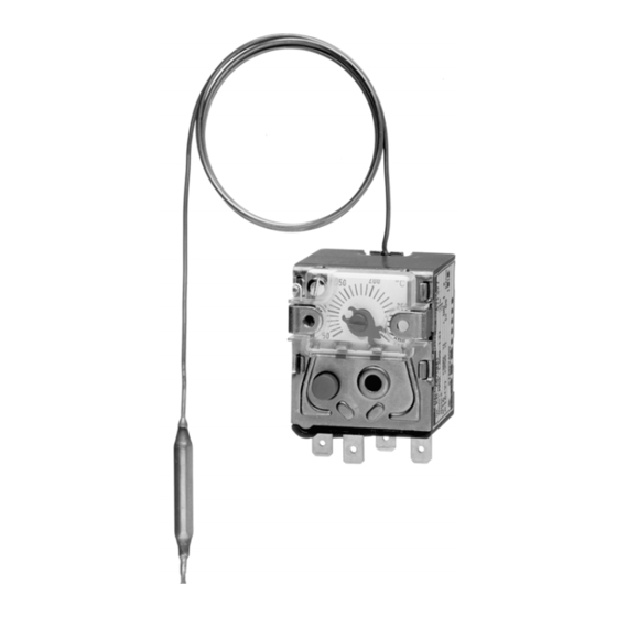
- Page 1 KM-70 Panel-mounting Thermostat B 60.2045.0 Operating Instructions 2008-10-24/00073778...
- Page 2 Please read these Operating Instructions before commissioning the instrument. Keep the manual in a place that is accessible to all users at all times. Please assist us to improve these operating instructions, where necessary. Your com- ments will be appreciated. Phone +49 661 6003-0 +49 661 6003-607 All neccessary settings and, where appropriate, alterations inside the instrument...
-
Page 3: Table Of Contents
Contents Page Introduction ................5 Typographical conventions ..............5 1.1.1 Warning signs ....................5 1.1.2 Note signs ....................5 Application ....................6 Marking ...................... 6 Safety notes ....................6 Instrument identification ............7 Nameplate ....................7 Type designation ..................7 Mounting .................. -
Page 5: Introduction
1 Introduction Typographical conventions 1.1.1 Warning signs Danger This symbol is used when there may be danger to personnel if the instructions are ignored or not followed correctly. Caution This symbol is used when there may be damage to equipment if the instructions are ignored or not followed correctly. -
Page 6: Application
1 Introduction Application Panel-mounting thermostats in the KM series are suitable for monitoring heat generators, boilers, heat exchangers and pumps in HVAC engineering. Cutting through or kinking the capillary of the KM series panel-mounting ther- mostat will lead to permanent instrument failure! Marking Version to DIN 3440: STB = protection temperature limiter... -
Page 7: Instrument Identification
2 Instrument identification Nameplate ( 1 ) ( 2 ) ( 3 ) ( 4 ) ( 5 ) ( 6 ) ( 7 )( 8 ) ( 9 ) ( 1 ) Type / permissible ambient temperature ( 2 ) Type code ( 3 ) Limit / Ambient temperature at which this thermostat was calibrated (option) / protection rating ( 4 ) Contact rating... -
Page 8: Mounting
3 Mounting Dimensions KM-70 ( 4 ) ( 2 ) ( 1 ) ( 5 ) ( 3 ) ( 1 ) Start of scale ( 2 ) End of scale ( 3 ) Faston connectors, A 6.3 x 0.6, DIN 46244... -
Page 9: Fixing The Panel-Mounting Thermostat
The minimum permissible bending radius of the capillary is 5 mm. The temperature probe must be installed in a JUMO pocket, otherwise the approval of the panel-mounting thermostat becomes invalid. The temperature probe must be completely immersed in the medium to be measured. -
Page 10: Approved Probes And Pockets
3 Mounting 3.3.2 Approved probes and pockets Forms A and H Ød Plain cylindrical probe Coiled probe Forms D, B and C Plain cylindrical probe, Probe mounting C with Plain cylindrical probe, threaded connector loose nipple, threaded with shoulder and union brazed or welded to at both ends nut, shoulder brazed or... - Page 11 3 Mounting Forms U and US Ø Ø G ½ Ø Ø Ø Ø D Screw-in pocket with Weld-in pocket with fixing screw and clip screw-in spigot Form A to DIN 3852/2, with fixing screw Forms UH and UO Screw-in pocket with Screw-in pocket open fixing screw, for hemp at end, with fixing screw...
- Page 12 3 Mounting Forms E and ES Ø Ø Screw-in pocket, with screw-in Weld-in pocket with welding shoulder, spigot Form A to DIN 3852/2, pocket secured with union nut, probe pocket secured with union nut, mounting C probe mounting C Forms Q and V Washer Scheibe...
-
Page 13: Permissible Loading On The Pocket
3 Mounting Permissible loading on the pocket 3.4.1 Pockets U, US, E and ES The values given below refer to the maximum loading on the probe mounting concerned. The maximum pressure that can be sealed depends on the installation conditions and may possibly be lower. 3.4.1.1 Steel pockets U, US, E and ES Materials... - Page 14 3 Mounting Permissible Temperature: +200°C incident flow velocity Thermal medium: water, oil Tube diameter D: 08 mm 10 mm ....15 mm Permissible incident flow velocity “v” at the maximum permissible pressure loading and different immersion tube lengths S.
- Page 15 3 Mounting 3.4.1.2 Stainless steel pockets U, US, E and ES Loading Material of tube and nipple: X 6 CrNiMoTl 17 122 Tube diameter D 8 x 0.75 mm 10 x 0.75 mm 15 x 0.75 mm Temperature or conical Max.
- Page 16 3 Mounting Forms A, H, UO, Q, V may only be used in pressure-free media. - To ensure their overall accuracy, the thermostats must only be used in con- junction with the pockets supplied by the factory. - Fitting several probes into a common pocket is only permitted with 2 or 3 cylindrical probes 6 mm dia.
-
Page 17: Installation
4 Installation Regulations and notes The electrical connection must only be carried out by qualified personnel. The choice of cable, the installation and the electrical connection must con- form to the requirements of VDE 0100 “Regulations on the Installation of Power Circuits with Nominal Voltages below 1000 V”... - Page 18 ( 1 ) Screw terminals up to 2.5 mm conductor cross-section ( 1 ) Clamping block ( 2 ) Connection screw Connection diagrams Type KM-70 Type KM-70 with (n.c.) break with (n.c.) break contact and lock-out contact, lock-out and additional signal...
-
Page 19: Settings
5 Settings Limit setting Adjust the switching point on the limit arm with a screwdriver before fitting the thermostat in position. ( 1 ) ( 2 ) ( 4 ) ( 3 ) ( 1 ) Scale division ( 2 ) Limit pointer ( 3 ) Top stop ( 4 ) Limit arm On limit ranges above 120°C, the limit that was set must be locked to prevent... -
Page 20: Limit Locking
5 Settings Limit locking ( 1 ) ( 2 ) ( 1 ) Cover ( 2 ) Lead-sealable screw Self-monitoring 5.4.1 Response to a measurement system fracture A fracture of the measurement system (leakage), will cause the circuit on the STB to open permanently and, in addition, the microswitch is locked out. -
Page 21: Instrument Description
16 (2) 230 V AC p.f. = 1 (0.6) temperature rise 0.25 230 V DC contact closing 400 V AC on falling KM-70 230 V AC temperature 0.25 230 V DC 400 V AC contact 16 (2) 230 V AC p.f. = 1 (0.6) - Page 22 6 Instrument description Operating water, oil, air, superheated steam medium Time constant in water in oil in air / superheated steam 0.632 ≤ 45 sec ≤ 60 sec ≤ 120 sec Mode of to EN 60 730-1 and EN 60 730-2-9 operation STB: 2 BFHKLP...
- Page 23 6 Instrument description Mean ambient (in % of scale span) referred to limit. temperature A deviation of the ambient temperature at the switch head and/or capillary effect from the +22°C calibration ambient temperature will produce a switching point shift: higher ambient temperature = lower switching point lower ambient temperature = higher switching point For temperatures with end of scale: ≥...
- Page 24 JUMO GmbH & Co. KG JUMO Instrument Co. Ltd. JUMO Process Control, Inc. Street address: JUMO House 8 Technology Boulevard Moritz-Juchheim-Straße 1 Temple Bank, Riverway Canastota, NY 13032, USA 36039 Fulda, Germany Harlow, Essex CM20 2TT, UK Phone: 315-697-JUMO Delivery address:...
Need help?
Do you have a question about the KM-70 and is the answer not in the manual?
Questions and answers