Advertisement
Quick Links
Aufbauthermostate, Typenreihe ATH.-SW-...
Surface-mounting Thermostats Series ATH.-SW-...
Thermostat pour montage en saillie Série ATH.-SW-...
ATHs-SW-...
Betriebsanleitung
Operating Instructions
Notice de mise en service
60303500T90Z001K000
V1.01/DE-EN-FR/00408318/2019-07-03
1. Einleitung
H
Aufbau-Thermostate der Typenreihe ATH-SW sind zugelassen als:
Temperaturwächter (TW)
Sicherheitstemperaturbegrenzer (STB)
Sicherheitstemperaturwächter STW (STB)
Baumusterprüfung nach:
- DIN EN 14597
H
- Druckgeräterichtlinie 2014/68/EU (alle Typen, außer ATH.-SW-2 und ATH.-SW-22)
Sicherheitshinweise
Knicken oder Durchtrennen der Fernleitung führt zum dauerhaften Ausfall des Gerätes.
Beim Verlegen der Fernleitung, Biegeradius ≥ 5 mm einhalten.
Beim Bruch des Messsystems kann Füllflüssigkeit austreten.
Physikalische und toxikologische Eigenschaften des Ausdehnungsmittels, welches im Falle eines
Messsystembruchs austreten kann:
Skalen-
Gefähr-
Brand- u. Explosionsge-
wasser-
endwert
liche
fahr
gefähr-
°C
Reaktion
dend
Zünd-
Explo-
temperatur
sionsgrenze
°C
Vol. %
flüssigkeitsgefüllt
< +200
nein
+355
0,6 - 8
ja
≥ 200 ≤ +350
nein
+490
ja
gasgefüllt
≥ 400 ≤ +500
nein
1
Über eine Gesundheitsgefährdung bei kurzzeitiger Einwirkung und geringer Konzentration, z.B. bei
Messsystembruch, gibt es bis jetzt keine einschränkende gesundheitsbehördliche Stellungnahme.
2. Gerät identifizieren
( 1 ) Typ / max. Gehäusetemperatur / Schutzart
( 2 ) Bestellschlüssel
( 3 ) Regelbereich / Schaltleistung / Verkaufsartikelnummer / Fabrikationsnummer
( 4 ) Prüfzeichen / Anschlussbild
( 5 ) Fertigungswoche
( 6 ) Fertigungsjahr
3. Montage
Allgemeines
Die Geräte dürfen nur mit passenden Schutzrohren betrieben werden.
Der Temperaturfühler muss vollständig in das Messmedium eingetaucht sein.
Im Betriebsmedium Luft muss ein Prozessanschluss ohne Schutzrohr gewählt werden.
Bei Belegung mit 2 Fühlern muß die werkseitig mitgelieferte Andruckfeder in dem Schutzrohr-
eingebaut sein.
Für die Schutzrohre 22, 32, 41, 42 und 45 aus den Werkstoffen St 35.8I ist bei Betriebstemperaturen
über 420°C die zulässige Betriebsdauer auf 200.000 Stunden begrenzt. Für die Anwendung in diesem
Bereich ist die TRD 508 zu beachten
Fühler-Ø
Schutzrohr-Ø
Material
6 mm
08 x 0,75 mm
Messing/Edelstahl
8 mm
10 x 0,75 mm
Messing/Edelstahl
2x6 mm
15 x 0,75 mm
Messing/Edelstahl
3.1 Aufbau-Thermostat befestigen
Nennlage (NL): nach DIN 16 257, NL 0 ... NL 90 (andere NL auf Anfrage)
Gehäuse öffnen
1. 4 Deckelschrauben ( 1 ) lösen
2. Gehäuseoberteil ( 2 ) abnehmen
Beim Zusammenbau auf korrekten Sitz der Dichtung ( 3 ) achten!
4. Abmessungen/Thermostate
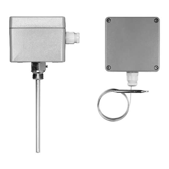
4.1 mit starrem Schaft ATHs SW-..
Kurzzeichen "s" (Starrer Schaft)
Der Gehäusezapfen wird in der erweiterten Hül-
senöffnung durch eine Feststellschraube befestigt.
(1) ATHs-SW-.., mit Schutzrohr „20" (1)
(2) ATHs-SW-.., mit Schutzrohr„32" (2)
4.2 mit Fernleitung ATHf-SW-..
Kurzzeichen ,,f'' (mit Fernleitung)
Schaltkopfbefestigung mit 4 Schrauben durch das
Gehäuseunterteil, Fernleitungsaustritt seitlich am
Gehäuse.
(3) ATHf-SW-..,
mit glattem Rundfühler 10", ohne Schutzrohr
4.3 mit Fernleitung ATHf-SW-..
Kurzzeichen ,,f'' (mit Fernleitung)
Schaltkopfbefestigung mit 4 Schrauben durch das
Gehäuseunterteil, Fernleitungsaustritt seitlich am
Gehäuse.
(4) ATHf-SW-.., mit Schutzrohr „20"
5. Belastbarkeit (Druck/Temperatur)
an dem Schutzrohr 20, 21, 30, 32, 40, 42 und 45, siehe Typenblatt 606710!
Die folgenden Werte beschreiben die maximale Belastbarkeit der betreffenden Anschlussart. Der maxi-
mal abdichtbare Druck ist von den Einbauverhältnissen abhängig und kann u.U. niedriger sein.
5.1
Zugelassene Temperaturfühler, Verschraubungen und Schutzrohre
Temperaturfühler
10 und 15
Verschraubungen
50, 52, 54, 60 und 65
Schutzrohre
20, 21, 22, 30, 31, 32, 40, 41, 42, 45 und 46
JUMO GmbH & Co. KG
Moritz-Juchheim-Straße 1 · 36039 Fulda, Germany
Tel.: +49 661 6003-0 · Fax: +49 661 6003-500 · mail@jumo.net · www.jumo.net
JUMO Mess- und Regelgeräte Ges.m.b.H.
Pfarrgasse 48 · 1230 Wien, Austria
Tel.: +43 1 610610 · Fax: +43 1 6106140 · info@jumo.at · www.jumo.at
JUMO Mess- und Regeltechnik AG
Laubisrütistrasse 70 · 8712 Stäfa, Switzerland
Tel.: +44 12 79 63 55 33 · Fax: +41 44 928 24 48 · info@jumo.ch · www.jumo.ch
JUMO Instrument Co. Ltd.
JUMO House · Temple Bank, Riverway · Harlow, Essex CM20 2DY, uk
Phone: +44 12 79 63 55 33 · Fax: +44 12 79 62 50 29 · sales@jumo.co.uk · www.jumo.co.uk
JUMO Process Control, Inc.
6733 Myers Road, East Syracuse, NY 13057, USA
Phone: 1 315 437 5866 · Fax: 1 315 437 5860 · e-mail: info.us@jumo.net · internet: www.jumousa.com
JUMO Régulation SAS
Actipôle Borny · 7 rue des Drapiers · B.P. 45200 · 57075 Metz - Cedex 3, France
Tél. : +33 3 87 37 53 00 · Fax : +33 3 87 37 89 00 · info.fr@jumo.net · www.jumo.fr
JUMO AUTOMATION S.P.R.L. / P.G.M.B.H. / B.V.B.A
Industriestraße 18 · 4700 Eupen, Belgique
Tél. : +32 87 59 53 00 · Fax : +32 87 74 02 03 · info@jumo.be · www.jumo.be
Lesen Sie diese Betriebsanleitung, bevor Sie das Gerät in Betrieb nehmen.
Bitte unterstützen Sie uns, diese Betriebsanleitung zu verbessern. Für Ihre Anregungen
sind wir dankbar.
Telefon
Telefax
Sollten bei der Inbetriebnahme Schwierigkeiten auftreten, bitten wir Sie, keine unzulässigen
ATHf-SW-...
Manipulationen oder Handlungen vorzunehmen. Der Gewährleistungsanspruch erlischt! Bitte
setzen Sie sich mit dem Lieferanten oder dem Stammhaus in Verbindung.
Please read these Operating Instructions before commissioning the instrument.
Please assist us to improve these operating instructions, where necessary. Your comments
will be appreciated.
Phone
Fax
If any difficulties should arise during starting up, please refrain from any unauthorized ma-
nipulations or actions. The warranty will become null and void! Please contact the supplier
or the head office.
Lisez cette notice avant de mettre en service l'appareil. Aidez-nous à améliorer cette no-
tice en nous faisant part de vos suggestions. Nous vous en serons reconnaissants.
Téléphone :
Télécopieur :
e-mail :
Service de soutien à la vente : 0892 700 733 (0,337 € /min)
Si vous rencontrez des difficultés lors de la mise en service, veuillez ne pas effectuer de
manipulations non autorisées. Vous pourriez compromettre votre droit à la garantie ! Veuil-
lez prendre contact avec nos services.
Introduction
ATH-SW series surface-mounting thermostats are approved as:
temperature monitors (TW)
safety temperature limiters (STB)
safety temperature monitors STW (STB)
Type examination to:
- DIN EN 14597
- Pressure Equipment Directive 2014/68/EU (all types, apart from ATH.-SW-2 and ATH.-SW-22)
Safety notes
Cutting through or kinking the capillary will lead to permanent instrument failure.
When routing the long-distance line ensure a bending radius of ≥ 5 mm.
Liquid may escape in the event of a measuring system fracture.
Physical and toxicological properties of the expansion medium that may escape in the event of a mea-
suring system fracture:
Angaben zur Toxikologie
Scale
Hazardous
limit value
reaction
°C
reizend gesundheits-
toxisch
gefährdend
1
ja
nein
< +200
no
1
≥ 200 ≤ +350
ja
nein
no
≥ 400 ≤ +500
1
At present, there is no restrictive statement from the health authorities concerning any danger to health
over short periods and at low concentrations.
Musterbeispiel
( 1 )
example
( 2 )
( 3 )
exemple
( 4 )
Mounting
General information
The devices may be operated only with suitable pockets.
The temperature probe must be fully immersed in the measurement medium.
When air is the measurement medium, you must choose a process connection without a pocket.
If 2 probes are assigned, the contact springs supplied ex works must be fitted in the pocket.
With pockets 22, 32, 41, 42, and 45 made from St 35.8I materials, the allowed operating period at
operating temperatures above 420°C is limited to 200,000 hours. Compliance with TRD 508 is es-
sential for applications in this range.
Probe Ø
Sheath Ø
6 mm
08 x 0.75 mm
8 mm
10 x 0.75 mm
2x6 mm
15 x 0.75 mm
25
( A )
G
(1)
Ø D
100
25
( A )
Ø 90
100
Ø 30
A = Verschraubung M 20x1,5
(2)
A = Threaded coupling M 20x1.5
A = Raccord fileté M 20x1,5
D
Resilience (pressure/temperature)
on the protection tube 20, 21, 30, 32, 40, 42 und 45, see data sheet 606710!
The values below refer to the maximum loading on the probe mounting concerned. The actual maxi-
mum sealable pressure depends on the mounting conditions and may possibly be lower.
Approved temperature probes, screw-connections and protection tubes
Temperature probes
Screw-connections
protection tubes
+49 661 6003-716
+49 661 6003-504
+49 661 6003-0
+49 661 6003-607
03 87 37 53 00
03 87 37 89 00
info.fr@jumo.net
Fire and explosion hazard hazardous to
Information about toxicology
waters
Ignition
Explosion li-
irritant
dangerous
temperature
mit
to
°C
Vol. %
health
liquid-filled
1
+355
0,6 - 8
yes
yes
1
+490
yes
yes
gas-filled
no
Instrument identification
( 5 )
( 1 ) Type / Max. housing temperatur / Protection
( 2 ) Order code
( 6 )
( 3 ) Control range / Contact rating / Sales number/Serial number
( 4 ) Approval mark / Connection diagram
( 5 ) Week of production
( 6 ) Year of production
Material
brass/stainless steel
brass/stainless steel
brass/stainless steel
Fixing the surface-mounting thermostat
Nom. position (NL): to DIN 16 257, NL 0 ... NL 90 (other NLs on request)
Opening the housing
1. Loosen the 4 cover screws ( 1 )
2. Remove the top of the housing ( 2 )
When re-assembling, make sure the seal is properly seated ( 3 )!
80
100
15
( A )
100
(3)
d
15
( A )
G
(4)
D
10 and 15
50, 52, 54, 60 and 65
20, 21, 22, 30, 31, 32, 40, 41, 42, 45 and 46
Dokumente und Zubehör
Documents and accessories / Documents et accessoires
- Dokumentation
- Konformitätserklärung / White Paper
- Zertifikate
- DGRL
- China RoHS
qr-603035-de.jumo.info
- Documentation
- Declaration of Conformity / White Paper
- Certificate
- DGRL
- China RoHS
qr-603035-en.jumo.info
- Documentation
- Déclaration de conformité / White Paper
- Certificat
- DGRL
- China RoHS
qr-603035-fr.jumo.info
Introduction
Les thermostats pour montage en saillie de la série ATH-SW sont utilisés en tant que :
Contrôleur de température (TW)
Limiteur de température de sécurité (STB)
Contrôleur de température de sécurité STW (STB)
Test suivant :
- DIN EN 14597
- Directive 2014/68/EU concernant les équipements sous pression (tous les types, hormis ATH.-SW-2 et ATH.-SW-22)
Nota de sécurité
Sectionnement et flambage du capillaire provoquent une panne durable.
Lors de la pose du capillaire, le rayon de courbure doit être ≥ 5 mm.
En cas de rupture du système de mesure, le liquide de remplissage peut s'échapper.
Caractéristiques physiques et toxicologiques du liquide d'expansion qui peut s'écouler en cas de rupture du
système de mesure :
Valeur fin
Réaction
Risque díexplosion et d'incendie incompatible
d'échelle
dangereuse
°C
toxic
Température d'in-
flammation
d'explosion
°C
Vol. %
Remplissage liquide
no
< +200
non
+355
0,6 - 8
≥ 200 ≤ +350
no
non
+490
Remplissage gaz
≥ 400 ≤ +500
1
Actuellement il n'existe aucune disposition restrictive à propos des risques sanitaires en cas d'émanation
momentanée ou de faible concentration, par ex. rupture du système de mesure.
Identification de l'appareil
( 1 ) Type / Température boîtier max. / Indice de protection
( 2 ) Code de commande
( 3 ) Plage de réglage / Pouvoir de coupure / Numéro d'article/Numéro de fabrication
( 4 ) Marque d'homologation / Schéma de raccordement
( 5 ) Semaine de fabrication
( 6 ) Année de fabrication
Montage
Généralités
Les appareils ne doivent être utilisés qu'avec des doigts de gant adaptés.
La totalité de la sonde de température doit être plongée dans le milieu de mesure.
Si le milieu de mesure est l'air, il faut choisir un raccord de process sans doigt de gant.
En cas de regroupement de 2 sondes, il faut monter dans le doigt de gant le ressort de
pression fourni.
Pour les doigts de gant 22, 32, 41, 42 et 45 en St 35.8I, la durée d'utilisation est limitée à 200 000 h si la
température d'utilisation est supérieure à 420 °C. Pour une utilisation dans cette plage, il faut respecter
les règles TRD 508.
Ø de la sonde Ø de la gaine
Matériau
6 mm
08 x 0,75 mm
Laiton/Acier inoxydable
8 mm
10 x 0,75 mm
Laiton/Acier inoxydable
2x6 mm
15 x 0,75 mm
Laiton/Acier inoxydable
Fixation du thermostat pour montage en saillie
Position nominale (NL) : suivant DIN 16 257, NL 0 ... NL 90 (autres NL sur demande)
Ouverture du boîtier
1. Dévisser les 4 vis du couvercle ( 1 )
2. Retirer la partie supérieure du boîtier ( 2 )
Il faut veiller à ce que le joint ( 3 ) soit correctement placé lors du montage !
Dimensions/Thermostats
with rigid stem ATHs-SW-..
Code s (rigid stem)
The housing spigot is secured in the enlarged
open end of the pocket by a fixing screw.
(1) ATHs-SW-.., with "20" protection tube
(2) ATHs-SW-.., with "32" protection tube
with capillary ATHf-SW-..
Code "f" (with capillary)
80
Mounting bracket with 4 screws through the
housing base, capillary exit at side of housing
(3) ATHf-SW-.., with plain "10" cylindrical
probe, without protection tube
with capillary ATHf-SW-..
Code "f" (with capillary)
Mounting bracket with 4 screws through the
housing base, capillary exit at side of housing
(4) ATHf-SW-.., with "20" protection tube
86
Résistance (pression/température)
sur la gaine de protection 20, 21, 30, 32, 40, 42 und 45, voir fiche technique 606710 !
Les valeurs suivantes indiquent la charge maximale admise des différents types de raccord. La pression
d'étanchéité maximale dépend des conditions de montage et peut être inférieure aux conditions nominales.
Sondes de température, filetages et gaine de protection autorisés
Sonde de température
10 et 15
Filetages
50, 52, 54, 60 et 65
Gaine de protection
20, 21, 22, 30, 31, 32, 40, 41, 42, 45 et 46
Données toxicologique
à l'eau
Limite
irritant
dangereux
toxique
pour la santé
1
oui
oui
non
1
oui
oui
non
non
Dimensions/Thermostats
avec tige rigide ATHs-SW-..
Abréviation "s" (tige rigide)
L'embout du boîtier est fixé dans l'ouverture
élargie du doigt de gant au moyen d'une vis de
blocage
(1) ATHs-SW-.., avec gaine de protection „20"
(2) ATHs-SW-.., avec gaine de protection „32"
avec capillaire ATHf-SW-..
Abréviation ,,f'' (avec capillaire)
Avec 4 vis dans la partie inférieure du boîtier,
sortie du capillaire sur le côté du boîtie
(3) ATHf-SW-.., avec sonde ronde lisse „10",
sans gaine de protection
avec capillaire ATHf-SW-..
Abréviation ,,f'' (avec capillaire)
Avec 4 vis dans la partie inférieure du boîtier,
sortie du capillaire sur le côté du boîtier
(4) ATHf-SW-.., avec gaine de protection „20"
Advertisement

Subscribe to Our Youtube Channel
Related Manuals for JUMO ATH -SW Series


Summary of Contents for JUMO ATH -SW Series
-
Page 1: Operating Instructions
Actipôle Borny · 7 rue des Drapiers · B.P. 45200 · 57075 Metz - Cedex 3, France Tél. : +33 3 87 37 53 00 · Fax : +33 3 87 37 89 00 · info.fr@jumo.net · www.jumo.fr - Documentation JUMO AUTOMATION S.P.R.L. -
Page 2: Electrical Connection
zulässige Anströmgeschwindigkeiten Permissible inflow velocities Vitesses d'écoulement recevable Temperatur: +200°C Temperature: +200°C Température: +200°C Wärmeträger: Luft ( 1 ), Wasser, Öl ( 2 ) Heat carrier: air ( 1 ), water, oil ( 2 ) Caloporteur: Air ( 1 ), eau, huile ( 2 ) Rohr-Ø...
Need help?
Do you have a question about the ATH -SW Series and is the answer not in the manual?
Questions and answers