
Related Manuals for JUMO ATH-EXx


Summary of Contents for JUMO ATH-EXx
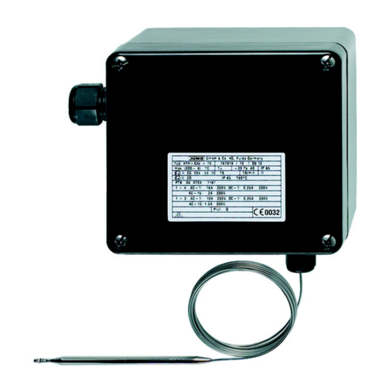
- Page 1 ATH-EXx Explosion-protected surface-mounted thermostat for potentially explosive gas atmosphere Zone 1 and potentially explosive dust atmosphere Zone 21 B 605051.0 Operating Instructions 2011-04-01/00379556...
- Page 2 Please read these Operating Instructions before commissioning the instrument. Keep the manual in a place that is accessible to all users at all times. Please assist us to improve these operating instructions, where necessary. Your sug- gestions will be appreciated. Phone+49 661 6003-0 +49 661 6003-607 All necessary settings and, where appropriate, alterations inside the instrument...
-
Page 3: Table Of Contents
Contents Seite Introduction ................5 Typographical conventions ..............5 1.1.1 Warning signs ....................5 1.1.2 Note signs ....................5 Application ....................6 Ex marking ....................6 Safety notes ....................6 Instrument identification ............7 Nameplate ....................7 Type designation ..................8 Mounting .................. -
Page 5: Introduction
1 Introduction Typographical conventions 1.1.1 Warning signs Danger This symbol is used when there may be danger to personnel if the instruc- tions are ignored or not followed correctly! Caution This symbol is used when there may be damage to equipment if the instruc- tions are ignored or not followed correctly! 1.1.2 Note signs Note... -
Page 6: Application
Cutting through or kinking the capillary of the surface-mounting thermostat, type ATH-EXx, will result in permanent failure of the instrument! Only use the ATH-EXx with TZ 679 in areas that are classified as areas with low mechanical risk. Ex marking II 2G Ex ed IIC T5 bzw. -
Page 7: Instrument Identification
2 Instrument identification Nameplate (10) ( 8 ) ( 1 ) ( 2 ) ( 3 ) ( 12 ) ( 9 ) (11) ( 4 ) ( 7 ) ( 5 ) ( 6 ) ( 1 ) Type Chapter 2.2 "Type designation", page 8 ( 2 ) Type code ( 3 ) Control range or limit value range / ambient temperature at which this... -
Page 8: Type Designation
2 Instrument identification Type designation ATH-EXx-. .- . Surface-mounting thermostat (with capillary) ATH-EXx Marking for explosion-protected version ATH-EXx-. .- . Code number for the function: 2 =0Temperature monitor (TW) with changeover contact. Limit adjustable within the housing. 7 =0Temperature limiter (TB) with changeover contact and restart lock-out. -
Page 9: Mounting
3 Mounting Dimensions ( 1 ) ( 1.1 ) ( 2 ) ( 1.2 ) ( 3 ) ( 4 ) ( 6 ) ( 5 ) ( 7 ) Ex cable gland M 20 x 1.5 x 6-12 (1.1) Screw-in thread Tightening torque: 3,75 Nm (1.2) Compression screw Tightening torque: for cable dia. -
Page 10: Opening The Surface-Mounting Thermostat
Minimum permissible bending radius of the capillary is 5 mm. The temperature probe must be mounted in a JUMO pocket, otherwise the approval of the surface-mounting thermostat becomes invalid. The temperature probe must completely immersed in the medium to be measured. -
Page 11: Permissible Operating Conditions At The Pocket
3 Mounting Permissible operating conditions at the pocket 3.5.1 Probe mountings 20 and 22 The values given below refer to the maximum loading on the probe mounting concerned. The maximum pressure which can be sealed depends on the mounting conditions and may possibly be lower. 3.5.1.1 Steel pockets Materials... - Page 12 3 Mounting Permissible Temperature: +200°C incident flow velocity air (1) Thermal medium: water, oil (2) Tube diameter D: 08 mm 10 mm 15 mm Permissible incident flow velocity “v” at the maximum permissible pressure loading and different immersion tube lengths “S” Permissible incident flow velocity “v”...
- Page 13 3 Mounting 3.5.1.2 Stainless steel pocket Materials Tube: X 6 CrNiMoTi 17122 Screw-in/weld-in nipple: X 6 CrNiMoTi 17122 Loading Temperature Tube diameter 8 x 0.75 mm or 10 x 0.75 mm 15 x 0.75 mm conical max. permissible max. permissi- max.
-
Page 14: Probe Mountings 10, 15, 21, 60, 65
3 Mounting 3.5.2 Probe mountings 10, 15, 21, 60, 65 Materials Choice of steel, stainless steel or brass Loading Only for use in unpressurized media. Probe mounting 60, 65 10, 21 Maximum temperature +55°C +200°C* +500°C* *depending on the control range Mounting the probe The temperature probe (2) must be immersed in the medium for its entire length, otherwise there will be appreciable deviations from the switching point. -
Page 15: Installation
4 Installation Regulations and notes In case of electrical connections in a potentially explosive area, it is necessary to comply with the relevant specifications. The electrical connection must only be carried out by qualified personnel. The choice of cable, the installation and the electrical connection must conform to the requirements of VDE 0100 “Regulations on the Installation of Power Circuits with Nominal Voltages below 1000 V”... -
Page 16: Electrical Connection
4 Installation Electrical connection Open the housing. "Opening the surface-mounting thermostat", page 9 Pass the connection cable (cable diameter 6 to 12 mm) through the Ex cable compression gland (1). "Dimensions", page 8 Make the connection to the terminals (2) in accordance with the connection diagram. -
Page 17: Settings
5 Settings Limit setting 5.1.1 TW, STW, TB (code 7) Open the housing. "Opening the surface-mounting thermostat", page 9 Set the limit on the setpoint spindle (1). ( 1 ) 5.1.2 STB (code 70) Important note for setup and operation! When the thermostat is used as a safety device for explosion protection in accordance with EU Directive 94/9/EC Annex II Sec. -
Page 18: Tb, Stb (Code 7-F Or 70-F)
5 Settings Setting the lim- Open the housing. "Opening the surface-mounting thermostat", page 9 its according to Warm up the temperature probe – in the system – to the intended limit specific system temperature (allow at least 5 minutes for the temperature to equalize), while characteristic using a calibrated reference measuring device to measure and observe the precise temperature at the temperature probe. -
Page 19: Resetting The Tb Or Stb Limiter
5 Settings Resetting the TB or STB limiter If the temperature at the probe goes above the limit that has been set, the electrical circuit 1-4 is opened and remains mechanically locked out. When the critical temperature has fallen to about 9-15% below the set limit, the TB or STB can be reset manually. -
Page 20: Instrument Description
6 Instrument description Technical data II 2G Ex ed IIC T5 bzw. T6 marking for potentially explosive gas atmospheres II 2D Ex tD A21 IP65 T95°C bzw. T80°C for potentially explosive dust atmospheres Explosion II 2G Equipment group II, Category 2, protection equipment for potentially explosive gas atmospheres II 2D... - Page 21 6 Instrument description Permissible ambient tem- Capillary Thermostat head °C perature in °C operation max. min. -20 (-50 et TZ 679) Max operating temperature of the cable screw-connection for the TZ 679: 70°C. Permissible probe tempera- max. limit +15% (+550°C with limit > 450°C) ture Permissible stor- max.
- Page 22 6 Instrument description Enclosure pro- EN 60 529 - IP 65 tection Operating Water, oil, air, superheated steam medium Time constant in water in oil in air / superheated 0.632 steam 45 s 60 s 120 s Mode of opera- according to EN 60 730-1 tion...
- Page 23 6 Instrument description Switching point in % of scale span, referred to the limit value at T +22°C. accuracy in upper third of scale TW, TB at start of scale in upper third of scale STW, STB at start of scale Mean ambient in % of scale span, referred to the limit value.
-
Page 24: Appendix
7 Appendix... - Page 25 7 Appendix...
- Page 26 7 Appendix...
- Page 27 7 Appendix...
- Page 28 7 Appendix...
- Page 29 7 Appendix...
- Page 30 7 Appendix...
- Page 32 JUMO GmbH & Co. KG JUMO Instrument Co. Ltd. JUMO Process Control, Inc. Street address: JUMO House 8 Technology Boulevard Moritz-Juchheim-Straße 1 Temple Bank, Riverway Canastota, NY 13032, USA 36039 Fulda, Germany Harlow, Essex CM20 2TT, UK Phone: 315-697-5866 Delivery address:...
Need help?
Do you have a question about the ATH-EXx and is the answer not in the manual?
Questions and answers