
Related Manuals for JUMO ATHf-SW


Summary of Contents for JUMO ATHf-SW
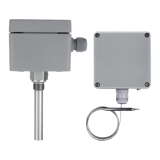
- Page 1 ATHs-SW-.. ATHf-SW-.. Surface-mounting Thermostats Series ATH.-SW-.. B 60.3035.0 Operating Instructions 02.03/00408320...
- Page 2 Please read these Operating Instructions before commissioning the instrument. Keep the manual in a place which is accessible to all users at all times. Please assist us to improve these operating instructions, where necessary. Your suggestions will be appreciated. Phone +49 661 6003-0 +49 661 6003-607 All necessary settings and possible adjustments inside the instrument are described in these operating instructions.
-
Page 3: Table Of Contents
Contents Page Introduction ................5 Typographical conventions ..............5 1.1.1 Warning signs ....................5 1.1.2 Note signs ....................5 Application ....................6 Marking ...................... 6 Safety notes ....................6 Instrument identification ............7 Nameplate ....................7 Type designation ..................7 Mounting .................. - Page 4 Contents Page Settings ..................22 Setpoint / limit setting ................22 5.1.1 TW, STW (STB), STB ................. 22 Resetting the STB ................... 23 Self-monitoring ..................24 5.3.1 Response to a system fracture ..............24 5.3.2 Response to falling below the temperature limit ........24 Use of the STW (STB) as STB ..............
-
Page 5: Introduction
1 Introduction Typographical conventions 1.1.1 Warning signs Danger This symbol is used where there may be danger to personnel if the instruc- tions are disregarded or not followed accurately. Caution This symbol is used where there may be damage to equipment if the instruc- tions are disregarded or not followed accurately. -
Page 6: Application
1 Introduction Application Surface-mounting thermostats ATH-SW series are approved as: ❏ Temperature monitor (TW) ❏ Safety temperature limiter (STB). ❏ Safety temperature monitor STW (STB) ❏ Type examination to: - DIN 3440 - Pressure Equipment Directive 97/23/EC (all types, except ATH.-SW-2 and ATH.-SW-22) Cutting through or kinking the capillary will result in permanent instrument failure! -
Page 7: Instrument Identification
2 Instrument identification Nameplate ATH-SW-2 Typ: System I 0 +100 °C System II 10(2) 1K/min TW89201 Geprüft (1) Type code (see type designation below), part number, serial number (2) Control range /limit value, contact rating, permissible ambient temperature, enclosure protection (3) Mark of conformity Type designation Type... -
Page 8: Mounting
3 Mounting Dimensions ATHs-SW-.., with pocket U cable gland M 20x1.5 Ø D ATHs-SW-.., with pocket UZS cable gland M 20x1.5 Ø 90 Ø 30... - Page 9 3 Mounting ATHf-SW-.., with plain cylindrical bulb no pocket cable gland M 20x1.5 ATHf-SW-.., with pocket U cable gland M 20x1.5...
-
Page 10: Opening The Housing
Minimum permissible bending radius of the capillary is 5 mm. The temperature probe must be installed in JUMO pockets, otherwise the approval of the surface-mounting thermostat becomes invalid. The temperature probe must be completely immersed in the medium. -
Page 11: Approved Probes And Pockets
3 Mounting 3.4.2 Approved probes and pockets ØD Ød Plain cylindrical bulb Screw-in pocket with Screw-in pocket screw-in spigot Form A with fixing screw and to DIN 3852/2, extension with fixing screw. Ø 25 Ø30 Ø 12 Ø 8 ØD Weld-in pocket Weld-in pocket with fixing screw and clamp... - Page 12 3 Mounting Screw-in pocket open at For code s, above +150°C end, with screw-in spigot probe temperature, screw-in Form A to DIN 3852/2, pocket open at end, with with fixing screw screw-in spigot Form A to DIN 3852/2, with fixing screw and extension For code f, For code f,...
-
Page 13: Permissible Loading On Pocket
3 Mounting Permissible loading on pocket 3.5.1 Pockets U, US, UZ, UZS The values below refer to the maximum loading on the probe mounting con- cerned. The maximum pressure that can be sealed depends on the installation conditions and may therefore be lower. 3.5.1.1 Steel pockets Material... - Page 14 3 Mounting Permissible Temperature: +200°C flow velocity air ( 1 ) Thermal medium: water, oil ( 2 ) Tube diameter D: 08 mm - - - - - - - - - - - - 10 mm ....15 mm Permissible flow velocity (m/sec) at maximum permissible pressure loading and different immersion tube lengths S...
- Page 15 3 Mounting 3.5.1.2 Stainless steel pockets Material Tube and nipple: X 6 CrNiMoTl 17 122 Tube diameter D Temperature 8 x 0.75 mm or taper 15 x 0.75 mm Maximum permissible pressure 100°C 92 bar 50 bar 150°C 88 bar 48 bar 200°C 83 bar...
- Page 16 3 Mounting 3.5.1.4 Probe mountings A, UO, UZO, Q und V (probe in direct contact with medium) The process connections A, UO, UZO, Q and V may only be used in unpres- surized media. To ensure their overall accuracy, the thermostats may only be used together with the pockets supplied by the factory.
-
Page 17: Mounting The Probe
3 Mounting Mounting the probe The temperature probe ( 2 ) must be completely immersed in the medium, otherwise there will be appreciable deviation from the switching point. In the case of thermostats with capillary (code f), the temperature probe is secured in the pocket by a clamp ( 1 ) with mountings U and US. -
Page 18: Installation
4 Installation Regulations and notes ❏ The electrical connection must only be carried out by qualified personnel. ❏ The choice of cable, the installation and the electrical connection must con- form to the requirements of VDE 0100 “Regulations on the installation of power circuits with nominal voltages below 1000 V”... -
Page 19: Electrical Connection
4 Installation Electrical connection ✱ Open housing. ➩ Chapter 3.2 “Opening the housing”, page 10. Steps ✱ Pull off protective cover. ✱ Pass the connecting cable (cable diameter 5 to 10 mm) through the cable gland ( A ). Screw connection for up to 2.5 mm cable cross-section. - Page 20 4 Installation Connection Twin thermostat diagrams System I and II: with changeover contact, switching action: TW, STW System I: with changeover contact, switching action: TW, STW System II: with break contact and lockout, switching action: STB System I and II: with break contact and lockout, switching action: STB...
-
Page 21: Closing The Housing
4 Installation 4.2.1 Closing the housing ✱ Make sure that the plastic seal ( 1 ) in the housing base ( 3 ) is seated cor- Thermostats as TW, STW (STB), rectly. ✱ Place the housing top ( 2 ) onto the housing base ( 3 ). ( 4 ) ( 4 ) ( 4 ) -
Page 22: Settings
5 Settings Setpoint / limit setting 5.1.1 TW, STW (STB), STB ✱ Open housing. ➩ Chapter 3.2 “Opening the housing”, page 10. ✱ Set the limit on the setpoint spindle ( 5 ) using a screwdriver. ✱ Close housing ➩ Chapter 4.2.1 “Closing the housing”, page 21. ( 1 ) Upper stop ( 2 ) Setpoint marker ( 3 ) Lower stop... -
Page 23: Resetting The Stb
5 Settings Resetting the STB After the temperature has dropped by about 10% of the span below the set limit (safe temperature limit), the microswitch can be reset. ✱ Remove the cover screws ( 1 ), ( 1 ) ( 1 ) lift cover ( 2 ). -
Page 24: Self-Monitoring
5 Settings Self-monitoring 5.3.1 Response to a system fracture On the STB and STW (STB), a fracture of the measuring system (leakage) will cause the circuit to open permanently. On the STB, the microswitch will additionally be locked. 5.3.2 Response to falling below the temperature limit If the probe cools down to below the minimum temperature of -10°C , the cir- cuit will open (STW (STB) and STB). -
Page 25: Instrument Description
6 Instrument description Technical data Permissible ambient Capillary Thermostat head with end of scale temperature STW (STB), STB max. +80°C +80°C +80°C -40°C -40°C +80°C < 200°C ≥ 200°C ≤ 350°C min. -20°C -20°C +80°C > 350°C ≤ 500°C -40°C -40°C +80°C Permissible... - Page 26 6 Instrument description Contact rating TW with differentials 3, 5, 6, 9% / STW (STB) 5, 7, 9% and STB 10 (2) A, 230 V AC +10%, 0.25 A, 230 V DC +10% p.f. = 1 (0.6) TW with differential 1.5% / STW (STB) 2% 6 (1.2) A, 230 V AC +10%, 0.15 A, 230 V DC +10% p.f.
- Page 27 6 Instrument description Material of capillary and End of scale Capillary Probe probe up to +200°C copper, Mat. Ref. 2.0090 copper, Mat. Ref. 2.0090 1.5 mm dia. brazed up to +350°C copper, Mat. Ref. 2.0090 st. steel, Mat. Ref. 1.4571 1.5 mm dia.
- Page 28 M. K. JUCHHEIM GmbH & Co JUMO Instrument Co. Ltd. JUMO PROCESS CONTROL INC. Street address: JUMO House 885 Fox Chase, Suite 103 Moltkestraße 13 - 31 Temple Bank, Riverway Coatesville, PA 19320, USA 36039 Fulda, Germany Harlow, Essex CM20 2TT, UK...
Need help?
Do you have a question about the ATHf-SW and is the answer not in the manual?
Questions and answers