
Subscribe to Our Youtube Channel
Related Manuals for JUMO KMf-20


Summary of Contents for JUMO KMf-20
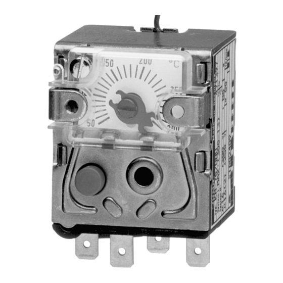
- Page 1 Panel-mounting Thermostats Type KMf-20 or KMf-70 B 60.2045 Operating Instructions 09.01/00073778...
- Page 2 Please read these Operating Instructions before commissioning the instrument. Keep the manual in a place which is accessible to all users at all times. Please assist us to improve these operating instructions where necessary. Your suggestions will be welcome. Phone in Germany (0661) 6003-716 abroad (+49) 661 6003-0...
-
Page 3: Table Of Contents
Contents Page Introduction ................3 Typographical conventions ..............3 1.1.1 Warnings ..................... 3 1.1.2 Note signs ....................3 Application ....................4 Identification ....................4 Safety notes ....................4 Instrument identification ............5 Nameplate ....................5 Type designation ..................5 Mounting ..................6 Dimensions .................... - Page 4 Contents Page Instrument description ............19 Technical data ..................19...
-
Page 5: Introduction
1 Introduction Typographical conventions 1.1.1 Warnings Danger This symbol is used when there may be danger to personnel if the instruc- tions are disregarded or not followed accurately! Caution This symbol is used when there may be damage to equipment if the instruc- tions are disregarded or not followed accurately! 1.1.2 Note signs Note... -
Page 6: Application
1 Introduction Application The panel-mounting thermostats Type KMf are suitable for monitoring heating systems, boilers, heat exchangers and pumps in HVAC engineering. Cutting through or kinking the capillary of the panel-mounting thermostats Type KMf will result in permanent instrument failure! Identification Arrangement to DIN 3440 as = safety temperature limiter... -
Page 7: Instrument Identification
2 Instrument identification Nameplate ( 1 ) ( 2 ) ( 3 ) ( 4 ) (1) Type code (see type designation) (2) Limit value / ambient temperature at which this thermostat has been calibrated (option) / permissible ambient temperature and type of protection (3) Contact rating (4) Mark of conformity... -
Page 8: Mounting
3 Mounting Dimensions 250 ° ( 4 ) ( 1 ) ( 3 ) ( 5 ) ( 2 ) ( 1 ) Start of scale ( 2 ) Faston connectors A 6.3 x 0.8 mm ( 3 ) End of scale ( 4 ) Panel ( 5 ) Reset button... -
Page 9: Securing The Panel-Mounting Thermostat
The minimum permissible bending radius of the capillary is 5 mm. The temperature probe must be installed in JUMO pockets, otherwise the approval of the panel-mounting thermostat becomes invalid. The temperature probe must be completely immersed in the medium. -
Page 10: Approved Probes And Pockets
3 Mounting 3.3.2 Approved probes and pockets Forms A and H Ød Plain cylindrical bulb Coiled bulb Forms D, B and C thread thread Plain cylindrical bulb, Probe form C with loose Plain cylindrical bulb threaded connector nipple, threaded on with shoulder and union brazed or welded to both ends. - Page 11 3 Mounting Forms U and US Ø 25 Ø30 ½" pipe G ½ Ø13 Ø 12 Ø 10 Ø 8 ØD Ø D Screw-in pocket with Weld-in pocket with fixing screw and clamp. screw-in spigot Form A to DIN 3852/2. With fixing screw.
- Page 12 3 Mounting Forms E and ES thread Ø Ø Ø Ø Screw-in pocket, Weld-in pocket with welding shoulder, pocket pocket secured with secured with union nut, probe form C. union nut, probe form C Forms Q and V washer washer Scheibe Scheibe seal...
-
Page 13: Permissible Pressure Loading On Pockets
3 Mounting Permissible pressure loading on pockets 3.4.1 Pockets U, US, E and ES The values below refer to the maximum loading on the probe mounting con- cerned. The maximum pressure that can be sealed depends on the installation conditions and may therefore be lower. 3.4.1.1 Steel pockets U, US, E and ES Material... - Page 14 3 Mounting Permissible Temperature: +200°C flow velocity Thermal medium: water, oil Tube dia. D: 08 mm 10 mm ....15 mm Permissible flow velocity v at max. permissible pressure loading and different immersion tube lengths S Water, oil Immersion tube length [mm]...
- Page 15 3 Mounting 3.4.1.2 Stainless steel pockets U, US, E and ES Loading Material of tube and nipple: X 6 CrNiMoTl 17 122 Tube diameter D 8 x 0.75 mm 10 x 0.75 mm 15 x 0.75 mm Temperature or taper Max.
- Page 16 3 Mounting Probe mountings A, H, UO, Q, V may only be used in pressure-free media. - To ensure their overall accuracy, the thermostats must only be used together with the pockets supplied by the factory. - Fitting several probes into a common pocket is only permitted with 2 or 3 cylindrical probes 6 mm dia.
-
Page 17: Installation
4 Installation Regulations and notes ❏ The electrical connection must only be carried out by qualified personnel. ❏ The choice of cable, the installation and the electrical connection must conform to the requirements of VDE 0100 “Regulations on the installation of power circuits with nominal voltages below 1000 V”, or the appropriate local regulations. - Page 18 Screw terminals up to 2.5 mm conductor cross-section ( 1 ) Clamping block ( 2 ) Connection screw Connection diagrams Type KMf-70 Type KMf-70 Type KMf-20 with n.c. (break) with n.c. (break) with changeover contact and lock-out contact, lock-out and contact additional signal...
-
Page 19: Settings
5 Settings Limit setting ✱ Adjust the switching point on the limit spindle with a screwdriver before installing the thermostat. ( 1 ) ( 2 ) ( 4 ) ( 3 ) ( 1 ) Scale ( 2 ) Limit pointer ( 3 ) Top stop ( 4 ) Limit spindle For limit setting ranges above 120°C, the set limit on the STB limiter has to be... -
Page 20: Limit Locking
5 Settings Limit locking ( 1 ) ( 2 ) ( 1 ) Cover ( 2 ) Screw suitable for lead sealing Self-monitoring 5.4.1 Response to a fracture of the measuring system On the STB and STW (STB), a fracture of the measuring system (leakage) will cause the circuit to open permanently. -
Page 21: Instrument Description
6 Instrument description Technical data Permissible ambient Capillary Thermostat with end of scale temperature head max. +80°C +80°C -40°C -40°C < 200°C min. ≥ 200°C ≤ 350°C -20°C -20°C Permissible end of scale +15% max., probe -50°C min. temperature Permissible +50°C max., -50°C min. - Page 22 6 Instrument description Protection EN 60 529 - IP 00 Operating water, oil, air, superheated steam medium Time constant 0.632 in water in oil in air / superheated steam ≤ 45 sec ≤ 60 sec ≤ 120 sec Action according to EN 60 730-1 STB, STW (STB): Type 2BK = automatic action with micro disconnection in operation, with break protection...
- Page 23 6 Instrument description Switching point (in % of scale span; accuracy referred to setpoint / limit value at T +22°C) STB, STW (STB) in upper third of scale at start of scale Mean (in % of scale span) referred to the limit value. ambient A deviation from the ambient temperature at the thermostat head and / or temperature...
- Page 24 M. K. JUCHHEIM GmbH & Co JUMO Instrument Co. Ltd. JUMO PROCESS CONTROL INC. Street address: JUMO House 885 Fox Chase, Suite 103 Moltkestraße 13 - 31 Temple Bank, Riverway Coatesville, PA 19320, USA 36039 Fulda, Germany Harlow, Essex CM20 2TT, UK...
Need help?
Do you have a question about the KMf-20 and is the answer not in the manual?
Questions and answers