Page 1
TECHNICAL & SERVICE MANUAL FILE NO. SAP-KRV96EHDS + SAP-CRV96EHDS SAP-KRV126EHDS + SAP-CRV126EHDS Destination: Europe 
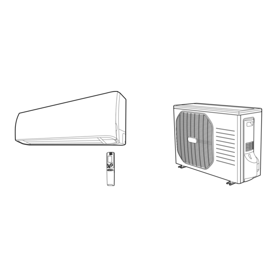
DC INVERTER SPLIT SYSTEM AIR CONDITIONER Indoor Model No. Product Code No. Outdoor Model No. Product Code No. SAP-KRV96EHDS 1 852 340 69 SAP-CRV96EHDS 1 852 340 73...
Page 2
When Transporting Important! Please Read Before Starting Be careful when picking up and moving the indoor and outdoor units. Get a partner to help, and bend your knees when lifting to reduce strain on your back. Sharp edges or This air conditioning system meets strict safety and thin aluminum fins on the air conditioner can cut your operating standards.
Table of Contents Page 1. OPERATING RANGE ........................2. SPECIFICATIONS 2-1. Unit Specifications ......................2-2. Major Component Specifications ..................2-3. Other Component Specifications ..................3. DIMENSIONAL DATA ........................4. REFRIGERANT FLOW DIAGRAM 4-1. Refrigerant Flow Diagram ....................5. PERFORMANCE DATA 5-1.
Page 4
Page 10. TROUBLESHOOTING 10-1. Precautions before Performing Inspection or Repair ............10-2. Method of Self-Diagnostics ....................10-3. Checking the Indoor and Outdoor Units ................10-4. Trouble Diagnosis of Fan Motor ..................10-5. Noise Malfunction and Electromagnetic Interference ............10-6. Checking and Troubleshooting when the Front Panel fails to work ........
1. OPERATING RANGE Temperature Indoor Air Intake Temp. Outdoor Air Intake Temp. 32 °C D.B. / 23 °C W.B. 43 °C D.B. Maximum Cooling 19 °C D.B. / 14 °C W.B. –15 °C D.B. Minimum 27 °C D.B. 24 °C D.B. / 18 °C W.B. Maximum Heating _ D.B.
2. SPECIFICATIONS 2-1. Unit Specifications Indoor Unit SAP-KRV96EHDS Outdoor Unit SAP-CRV96EHDS Power Source 220 to 240V Single-Phase 50Hz Voltage Rating 230V Performance Cooling Heating Capacity 2.65 ( 0.9 to 3.6 ) 3.60 ( 0.9 to 4.9 ) BTU/h 9,000 ( 3,100 to 12,200 )
Page 7
Indoor Unit SAP-KRV126EHDS Outdoor Unit SAP-CRV126EHDS Power Source 220 to 240V Single-Phase 50Hz Voltage Rating 230V Performance Cooling Heating Capacity 3.50 ( 0.9 to 3.9 ) 4.80 ( 0.9 to 5.4 ) BTU/h 11,900 ( 3,100 to 13,300 ) 16,400 ( 3,100 to 18,400 ) Air Circulation (High) Moisture Removal (High)
2-2. Major Component Specifications 2-2-1. Indoor Unit Indoor Unit SAP-KRV96EHDS Control PCB Part No. CB-KRV96EHDS Controls Microprocessor Control Circuit Fuse 250V 3.15A Remote Control Unit RCS-6MHVPUSW4E Type Cross-Flow Q'ty ... Dia. and Length 1 ... D85 / L551 Fan Motor...
Page 9
Indoor Unit SAP-KRV126EHDS Control PCB Part No. CB-KRV126EHDS Controls Microprocessor Control Circuit Fuse 250V 3.15A Remote Control Unit RCS-6MHVPUSW4E Type Cross-Flow Q'ty ... Dia. and Length 1 ... D85 / L551 Fan Motor Type DC Motor Model ... Q'ty SIC-39CVL-D847-3-A ... 1 No.
2-2-2. Outdoor Unit Outdoor Unit SAP-CRV96EHDS Control PCB Part No. CB-CRV96EHDS Controls Microprocessor Control Circuit Fuse 250V 20A Compressor Type DC Rotary (Hermetic) Compressor Model / Nominal Output C-1RVN68H0K / 675W Compressor Oil ... Amount FV50S ... 350 Coil Resistance (Ambient Temp. 20 °C) R - S : 0.632 S - T : 0.632 T - R : 0.632...
Page 11
Outdoor Unit SAP-CRV126EHDS Control PCB Part No. CB-CRV126EHDS Controls Microprocessor Control Circuit Fuse 250V 20A Compressor Type DC Rotary (Hermetic) Compressor Model / Nominal Output C-1RVN68H0K / 675W Compressor Oil ... Amount FV50S ... 350 Coil Resistance (Ambient Temp. 20 °C) R - S : 0.632 S - T : 0.632 T - R : 0.632...
5-2. Air Throw Distance Charts Indoor Unit SAP-KRV96EHDS Cooling 27 °C Room air temp. : Fan speed High Horizontal distance (m) : Flap angle 0° , : Axis air velocity 0° : Flap angle 30°, : Axis air velocity 30°...
Page 19
Indoor Unit SAP-KRV126EHDS Cooling 27 °C Room air temp. : Fan speed High Horizontal distance (m) : Flap angle 0°, : Axis air velocity 0° : Flap angle 30°, : Axis air velocity 30° Heating 20 °C Room air temp. : Fan speed High Horizontal distance (m)
6. ELECTRICAL DATA 6-1. Electrical Characteristics Indoor Unit SAP-KRV96EHDS Outdoor Unit SAP-CRV96EHDS Cooling Indoor Unit Outdoor Unit Complete Unit Fan Motor Fan Motor + Compressor Performance at 230V Single-phase 50Hz Rating conditions Running amp. 0.34 2.92 3.26 Power input 27 °C D.B. / 19 °C W.B.
6-2. Electric Wiring Diagrams Indoor Unit SAP-KRV96EHDS SAP-KRV126EHDS To avoid electrical shock hazard, be sure to WARNING disconnect power before checking, servicing and/or cleaning any electrical parts. JOINT BOX TERMINAL BASE GRN/YEL EVAPORATOR EARTH PLATE FLAP MOTOR (UPPER) ELEC-JB1 (WHT)
Page 22
Outdoor Unit SAP-CRV96EHDS SAP-CRV126EHDS To avoid electrical shock hazard, be sure to WARNING disconnect power before checking, servicing and/or cleaning any electrical parts. NOISE FILTER ACIN1 OUT1 REACTOR ACIN2 OUT2 SICOM FERRITE AC250V CONTROLLER CORE TERMINAL PLATE (BLK) (WHT) (WHT) (WHT) (WHT) T-RUN/TEST...
7. INSTALLATION INSTRUCTIONS 7-1. Installation Site Selection 7-1-1. Indoor Unit To prevent abnormal heat WARNING generation and the possibility of fire, do not place obstacles, 15 cm min. 5 cm enclosures and grilles in front 5 cm min. min. of or surrounding the air conditioner in a way that may block air flow.
Page 24
7-1-2. Outdoor Unit Exhaust fan AVOID: Hot air Heat source heat sources, exhaust fans, etc. (Fig. 4) damp, humid or uneven locations. Outdoor unit position the outdoor unit in a protected location where snow will not blow into it. choose a place as cool as possible. Fig.
7-2. Recommended Wire Length and Diameter Regulations on wiring diameter differ from locality to locality. For field wiring requirements, please refer to your local electrical codes. Carefully observe these regulations when carrying out the installation. Table 2 lists recommended wire lengths and diameters for power supply systems. NOTE Refer to the wiring system diagram (Fig.
7-3. Remote Control Unit Installation Position The remote control unit can be operated from either a non-fixed position or a wall-mounted position. To ensure that the air conditioner operates correctly, do not install the remote control unit in the following places: In direct sunlight Behind a curtain or other place where it is covered More than 8 m away from the air conditioner...
7-4. How to Test Run the Air Conditioner After turning on power to the air conditioner, use the remote controller and follow the steps below to conduct the test run. (1) Set the remote controller in Test Run mode. (Fig. 8a) Press and hold the LED CLEAN button.
Page 28
7-5. Removing and Installing the Grille Front panel Basically, these models can be installed and wired without removing the grille. If access to any internal part is needed, follow the steps as given below. How to remove the grille (1) Open the front panel until it is nearly horizontal, grasp the sections near the front panel arms on both sides, and then pull forward to remove the front panel.
8. MAINTENANCE 8-1. Address Setting of the Remote Control Unit The address can be set in order to prevent interference between remote controllers when two indoor units are installed near each other. The address is normally set to "A." To set a different address, it is necessary to change the address on the Fig.
8-2. Removing and Mounting the Drain Hose Ture the hose (1) Before removing the drain hose, check the location of the drain cramp at the end of the hose. Drain hose Stopper Turn the hose counterclockwise to remove the drain cramp from the stopper and pull the hose out.
8-4. Removing the Electrical Component Box (1) Remove the temperature / humidity sensor from the sensor plate. (2) Remove the operation box of the main body. Temperature / Humidity sensor (3) Remove the electrical component box pad plate. (Release the tabs.) Operation box (Release the tab.) Sensor plate...
Page 32
(7) Remove the screw and the drain guide plate. (The screw tighten the drain guide plate and the Electrical component box electrical component box.) Hook (8) Remove the ground terminal and the heat exchanger temperature sensor. Pull out the ground terminal lead and the heat exchanger temperature sensor lead from hook.
8-5. Removing the P.C.Board Tab 2 (1) Remove the indicator. (2) Release the tab 1. Then, release the tab 2 and separate the electrical component box into 2 parts. Electrical component box Tab 1 Indicator Release the right and left side tabs. Panel motor (3) Disconnect all connectors on the control.
8-7. Removing and Mounting the UV antibacterial filtration unit NOTE UV antibacterial filtration unit UV unit 8-7-1. Removing the UV unit Screw (1) Remove the screw and release 4 tabs. Remove the UV unit cover. UV unit cover UV unit (2) Slightly roatate the UV unit to torward you (Arrow 1) and pull it out (Arrow 2).
8-7-2. Mounting the UV unit Hole (1) Insert the UV unit into the joint section like the right side figure. UV unit 8-8. Removing the Drain Pan (Air Outlet Ass'y) Remove the hooks (1), (2) and (3) which secure the drain pan. (1) Right side drain pan Press the back right in the arrow direction, and the hooked part can be released.
(3) Left side drain pan Press the back left in the arrow direction, and the hooked part can be released. (4) Removing the drain hose Refer to "8-2. Removing and Mounting the Drain Hose" for the details. Drain pan 8-9. Removing and Mounting the Fan Motor Release the fan motor lead from hook.
8-10. Removing the Fan NOTE Be sure to proceed after having removed the drain pan (Air Outlet Ass'y) and fan motor according to sections "8-8. and 8-9." (1) Remove 3 screws. Heat exchanger (2) Uphold the left side of the head exchanger so that it is not seated anywhere (so as to remove the fan).
8-11. Disconnecting and Connecting Positive Connector for Outdoor Unit One of the two types of connectors illustrated at left is used. Their basic structure is the same for each. How to Disconnect Hold the resin connector cover, and pull the connector off. You cannot disconnect the connector by pulling the wire since it is locked inside.
9. FUNCTIONS 9-1. Operation Functions Emergency operation SENSOR DRY Emergency operation is available when the remote During DRY operation, the system adjusts the room temperature and fan speed according to the conditions in the controller malfunctions, has been lost, or otherwise room, in order to maintain a comfortable room environment.
HIGH POWER NIGHT SETBACK This function acts to raise the power but keeps the AC system in • When NIGHT SETBACK operation is set, the temperature and the same operating mode. fan speed settings will be adjusted automatically to allow This function is set with the HIGH POWER button on the remote comfortable sleep.
9-2. Protective Functions Overload prevention during heating Cold-air prevention during heating During HEAT operation, the temperature of the indoor heat During heating, the fan speed is set to "LL" (very low) or stopped. exchanger is used to control the frequency and lessen the load As the temperature of the indoor heat exchanger rises, the fan on the compressor before the protective device is activated.
Defrost detection and release CT (Peak current cut-off control) This function prevents the circuit breaker or fuse from operating Reverse-Cycle Defrosting to open the circuit. This function works when electrical current has increased due to an increase in the cooling / heating load, or to a decrease in the power supply voltage.
10. TROUBLESHOOTING 10-1. Precautions before Performing Inspection or Repair After checking the self-diagnostics monitor, turn the power OFF before starting inspection or repair. High-capacity electrolytic capacitors are used inside the outdoor unit controller (inverter).They retain an electrical charge (charging voltage DC 310 V) even after the power is turned OFF, and some time is required for the charge to dissipate. Be careful not to touch any electrified parts before the controller LED (red) turns OFF.
Page 44
(1) Self-diagnostics Lamps (1) OPERATION lamp REMOTE CONTROL receiver (2) TIMER lamp (3) LED CLEAN lamp If there is no trouble, the lamps neither blink nor illuminate. Since the indications cover various units, the corresponding items listed below may not be present in some models..
(2) If the self-diagnostics function fails to operate • No indicators illuminate and the Check the indoor unit. indoor fan does not rotate. • Check the power voltage. Blown Is the fuse blown? Normal Replace the circuit board or the fuse. Replace the controller.
Page 46
(3) How to Identify a Serial Communication Error If the lamps on the main body show the following conditions after the completion of self-diagnosis, a communication error between the indoor unit and outdoor unit might be considered. In such a case, identify the breakdown section by using the following procedure. Refer to "Method of Self-Diagnosis"...
Page 47
(3-2) Condition: E12 1. Disconnect the inter-unit wiring on the outdoor unit side. 2. Operate the system in TEST RUN mode. Then, five minutes later, perform the self-diagnosis. Condition: E01 What is the self-diagnosis result ? Condition: E12 1. Disconnect the inter-unit wiring on the indoor An error in the P.
10-4. Trouble Diagnosis of Fan Motor 10-4-1. Indoor Fan Motor This indoor DC fan motor contains an internal control PCB. Therefore, it is not possible to measure the coil resistance, and the following procedure should be used to check the motor. To perform diagnosis, operate the unit in cooling mode with indoor fan speed "High".
10-4-2. Outdoor Fan Motor This outdoor DC fan motor contains an internal control PCB. Therefore, it is not possible to measure the coil resistance, and the following procedure should be used to check the motor. Perform the trouble diagnosis by Test Run mode described on Installation Instructions. Important: (A) Turn OFF the power before connecting or disconnecting the motor connectors.
10-5. Noise Malfunction and Electromagnetic Interference An inverter A/C operates using pulse signal control and high frequencies. Therefore, it is susceptible to the effects of external noise, and is likely to cause electromagnetic interference with nearby wireless devices. A noise filter is installed for ordinary use, preventing these problems. However, depending on the installation conditions, these effects may still occur.
10-6. Checking and Troubleshooting when the Front Panel fails to work 10-6-1. Checking the Front Panel when it fails to work during operation (1) Is the grille mounted in place? (Check in particular that the upper right screw is Upper right screw adequately tightened.) Flap Screw...
Page 52
10-6-2. Making a Diagnosis of the Panel Motor (1) If no abnormality was found in (1) to (3) of the previous section, then carry out diagnosis of the panel motor, which activated the front panel. (2) Remove the panel motor connector. Panel motor Connector Panel motor...
11. CHECKING ELECTRICAL COMPONENTS 11-1. Measurement of Insulation Ground wire Resistance Clip The insulation is in good condition if the resistance exceeds 1M ohm. Probe 11-1-1. Power Supply Cord Insulation Clamp the grounding wire of power cord with the lead tester clip of the insulation resistance tester and measure the Fig.
11-2. Checking Continuity of Fuse Fuse on PCB Ass'y Remove the PCB Ass'y from the electrical component box. Then pull out the fuse from the PCB Ass'y. (Fig. 5) Check for continuity using a multimeter as shown in PCB Ass'y Fig.
12. REFRIGERANT R410A: SPECIAL PRECAUTIONS WHEN SERVICING UNIT 12-1. Characteristics of New Refrigerant R410A 12-1-1. What is New Refrigerant R410A? R410A is a new refrigerant that contains two types of pseudo-non-azeotropic refrigerant mixture. Its refrigeration capacity and energy efficiency are about the same level as the conventional refrigerant, R22. 12-1-2.
Page 56
Tubing precautions Refrigerant R410A is more easily affected by dust or moisture compared with R22, thus be sure to temporarily cover the ends of the tubing with caps or tape prior to installation. Never use 0.7mm-thick copper tubing or tubing which is less than 0.8mm in thickness, since air conditioners with R410A are subject to higher pressure than those using R22 and R407C.
12-3. Tools Specifically for R410A For servicing, use the following tools for R410A Tool Distinction Tool Name Gauge manifold Charging hose Gas leak detector Refrigerant cylinder Charging cylinder Refrigerant recovery unit Vacuum pump with anti-reverse flow (*1) Tools specifically for R410A (Solenoid valve-installed type, which prevents oil from flowing back into the unit when the power is off, is recommended.) Vacuum pump (*2)...can be used if the following adapter is attached.
12-5. In Case of Compressor Malfunction Should the compressor malfunction, be sure to make the switch to a replacement CAUTION compressor as quickly as possible. Use only the tools indicated exclusively for R410A. See "12-3. Tools Specifically for R410A." 12-5-1. Procedure for Replacing Compressor (1) Recovering refrigerant Any remaining refrigerant inside the unit should not be released to the atmosphere, but recovered using the...
Page 59
(5) Recharging Configuration and characteristics of cylinders Be sure to charge the specified amount of Valve refrigerant in liquid state using the service port of the wide tube service valve. The proper amount is listed on the unit's nameplate. When the entire amount cannot be charged all at once, charge gradually while operating the unit in Cooling Operation.
12-6. In Case Refrigerant is Leaking Never attempt to charge additional refrigerant when refrigerant has been leaking CAUTION from the unit. Follow the procedure described below to locate points of leaks and carry out repairs, then recharge the refrigerant. (1) Detecting Leaks Use the detector for R410A to locate refrigerant leak points.
12-7. Charging Additional Refrigerant 12-7-1. When Tubes are Extended Observe the proper amount of refrigerant as stated in this service manual or the installation manual that came with the indoor unit. Charge additional refrigerant in liquid state only. Never charge additional refrigerant if refrigerant is leaking from the unit. Follow CAUTION instructions given in "12-6.
Page 63
FEATURES This air conditioner is an inverter type unit that automatically adjusts capability as appropriate. Details on these functions are provided below; refer to these descriptions when using the air conditioner. • Microprocessor Controlled Operation • Hot Start Heating System The interior compartment of the remote control unit Right from the start, the air is warm and comfortable.
PRODUCT INFORMATION ELECTRICAL REQUIREMENTS If you have problems or questions concerning your Air Conditioner, you will need the following information. 1. All wiring must conform to the local electrical codes. Model and serial numbers are on the nameplate on the Consult your dealer or a qualified electrician for bottom of the cabinet.
NAMES OF PARTS UNIT DISPLAY AND OPERATION BUTTON Air intakes INDOOR UNIT INDOOR UNIT TEST button OPERATION button Air outlet OPERATION lamp REMOTE CONTROL Remote control unit receiver TIMER lamp LED CLEAN lamp Drain hose IMPORTANT Refrigerant tubes Avoid using radio equipment such as mobile phone near (within 1 m) the remote control receiver.
REMOTE CONTROL UNIT (DISPLAY) Displayed when transmitting data Displayed when indoor unit sensor is in use Displayed when setting temperature Displayed when temperature is shown Displayed when setting timer Displayed when the time display is set to 12-hour time. Symbols (1) Operation mode (4) Timer 24-hour clock with ON/OFF...
REMOTE CONTROL UNIT Transmitter When you press the buttons on the remote control unit, the mark appears in the display to transmit the setting changes to the receiver in the air conditioner. Display Information on the operating conditions is displayed while the remote control unit is switched on.
Page 68
Sensor A temperature sensor inside the remote control unit senses the room temperature. ON/OFF operation button This button is for turning the air conditioner on and off. 1 HR. TIMER button (1-HOUR OFF TIMER) : When you press this button, regardless of whether the unit is operating or stopping, the unit operates for one hour and then shuts down.
USING THE REMOTE CONTROL UNIT HOW TO INSTALL BATTERIES REMOTE CONTROL UNIT INSTALLATION POSITION The remote control unit may be operated either from a non-fixed position or from a wall-mounted position. To ensure that the air conditioner operates correctly, DO NOT install the remote control unit in the following places: DO NOT •...
OPERATION WITH THE REMOTE CONTROL UNIT 1. Automatic Operation 2. Manual Operation This unit automatically switches between cooling operation and heating operation according to the difference between the room temperature and the temperature setting. STEP 2 STEP 3 STEP 2 STEP 1 STEP 4 STEP 5...
3. Adjusting the Fan Speed A. In Cooling and DRY Mode: ( A. Automatic fan speed When the night setback mode is selected, the air conditioner Simply set the FAN SPEED selector button to the automatically raises the temperature setting 1 °C when 30 minutes have passed after the selection was made, and then position.
7. HIGH POWER Mode To cancel, press the LED CLEAN button again. • When the LED CLEAN button is pressed, the UV anti-bacterial unit operates for one hour and cleans air blown from the air conditioner. NOTE • Pressing the MODE selector button cancels LED CLEAN mode. •...
SETTING THE TIMER 3. How to set the ON time (Example) To start operation at 7:10 am. Operation Indication Press the ON TIME setting The timer indication is button once. displayed, and the present ON NOTE time is shown. In the descriptions below, the following settings are used for the Press the Advance, Return The timer indication...
USING THE 1-HOUR OFF TIMER 1. 1-Hour OFF Timer CAUTION When the humidity is high, the vertical vanes should be in the front position during the cooling or dehumidifying operation. If the vertical vanes are positioned all of the way to the right or left, condensation may begin to form around the air vent and drip down.
OPERATION WITHOUT THE Removing the front panel • Push the front panel all the way upward. REMOTE CONTROL UNIT Pull while supporting the nearest point of the arms toward you. • Remove the sub grill attached to the rear of the front panel after setting the four levers to loosen.
How to replace the anti-mold filter Trouble Possible Cause Remedy Insert the top of the anti-mold filter, align the two protrusions with the center hook at bottom, then mount the filter into place. Air conditioner does 1. Power failure. 1. Restore power. Press the locations marked by the arrows and close the front not run at all.
Page 77
SANYO Electric co., Ltd. Osaka, Japan Jan. / 2007 Printed in Japan (T)