
Subscribe to Our Youtube Channel
Related Manuals for DeLonghi DFS 090 DO


Summary of Contents for DeLonghi DFS 090 DO
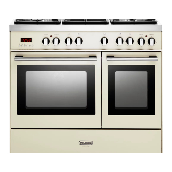
- Page 1 Users Operating Instructions Before operating this cooker, please read these instructions carefully DFS 090 DO Twin cavity Dual Fuel Cooker...
- Page 2 Introduction Congratulations on your purchase of this Delonghi Dual fuel cooker which has been carefully designed and produced to give you many years of satisfactory use. Before using this appliance it is essential that the following instructions are carefully read and fully understood.
-
Page 3: Important Precautions And Recommendations
Important precautions and recommendations After having unpacked the appliance, check to ensure that it is not damaged. In case of doubt, do not use it and consult your supplier or a professionally qualified techni- cian. Packing elements (i.e. plastic bags, polystyrene foam, nails, packing straps, etc.) should not be left around within easy reach of children, as these may cause serious injuries. -
Page 4: Features And Technical Data
Features and technical data Fig. 1.1 Gas burners 1. Auxiliary burner (A) 1,00 kW 2. Semi-rapid burner (SR) 1,90 kW 3. Rapid burner (R) 3,15 kW 4. Double-ring burner (PB) 3,45 kW NOTE: The electric ignition is incorporated in the knobs... -
Page 5: Control Panel Overview
Control panel Fig. 2.1 CONTROL PANEL - Controls description 1. Electronic clock/end cooking timer (main left oven only) 2. Fan main oven thermostat knob 3. Fan main oven switch knob 4. Front left burner control knob 5. Rear left burner control knob 6. -
Page 6: Electronic Clock/Alarm
Electronic clock/end cooking timer (main left oven only) The electronic programmer is a device Cooking with automatic with the following functions: switch-off (main left oven only) – 24 hours clock with illuminated display – Timing of oven cooking with automatic The aim of this function is to automatically switch-off (max. -
Page 7: How To Use The Hob Burners
How to use the hob burners Hob burners Each hob burner is controlled by a separate gas tap operated by a control knob (fig. 4.1) which has 3 positions marked on the control panel, these are: – Symbol : tap closed (burner off) –... - Page 8 Choice of burner The burner must be choosen according to the diameter of the pans and energy required. Fig. 4.2 Burners Pan diameter Auxiliary 16 cm Semi-rapid 16 ÷ 22 cm Rapid 20 ÷ 24 cm Double-ring up to 30 cm do not use pans with concave or convex bases Saucepans with handles which are excessively heavy, in relationship to the weight of the pan, are safer as they are less likely to tip.
-
Page 9: How To Use
How to use the Fan left oven (main oven) General features Operating principles Heating and cooking in the FAN oven are Attention: the oven door becomes obtained in the following ways: very hot during operation. Keep children away. a. by forced convection A fan sucks in the air contained in the The heating and cooking in electrical hot oven muffle, which sends it through the... -
Page 10: Oven Light
Fig. 5.2 Fig. 5.1 Thermostat knob (Fig. 5.1) This only sets the cooking temperature and does not switch the oven on. Rotate clockwise until the required temperature is reached (from 50 to 250°C). The light above the temperature selector will illuminate when the oven is swiched on and turns off when the oven reaches the correct temperature. -
Page 11: Cooking Advice
HOT AIR COOKING The circular element and fan come on. The heat is dispersed by forced convection and the temperature can be regulated to between 50° and 250°C via the thermostat knob. The oven does not require preheating. Recommended for: Food which has to be well-cooked outside and soft or rosy inside, for example lasagne, lamb, roast beef, whole fish etc. -
Page 12: Safety Precautions
REGENERATION Set the switch to position and the thermostat knob to position 150° C. Bread becomes fragrant again if wet with a few drops of water and put into the oven for about 10 minutes at the highest temperature. ROASTING To obtain classical roasting, it is necessary to remember: –... -
Page 13: How To Use Conventional Right Oven
How to use the Conventional right oven General features Attention: the oven door becomes very hot during operation. Keep children away. As its name indicates, this is an oven that presents particular features from an operational point of view. The conventional oven is provided with 3 heating elements which are: –... - Page 14 Operating principles Heating and cooking in the CONVENTIONAL oven are obtained in the following ways: a. by natural convection The heat is produced by the upper and lower heating elements. b. by radiation The heat is radiated by the infra red grill element. Thermostat knob (Fig.
-
Page 15: Use Of The Grill
GRILLING The infrared grill element comes on. The heat is dispersed by radiation. Set the thermostat knob to between 50° and 200°C. Always grill with the oven door closed. For cooking hints, see the chapter “USE OF THE GRILL”. Recommended for: Intense grilling, browning, cooking au gratin and toasting etc. -
Page 16: Cooking Guide
Cooking guide Temperature and times given are approximate, as they will vary depending on the quality and amount of food being cooked. Remember to use ovenproof dishes and to adjust the oven temperature during cooking if necessary. Oven cooking temperatures APPROX. -
Page 17: Important Notes
Important notes Installation, and any demonstration, information or adjustments are not included in the warranty. The cooker must be installed by a qualified person in accordance with the Gas Safety (Installation and Use) (Amendment) Regulations 1990 and the relevant building/l.E.E Regulations. -
Page 18: Do's And Do Not's
Do’s and do not’s Do’s and do not’s • Do always grill with the oven door closed. • Do read the user instructions carefully before using the cooker for first time. • Do allow the oven to heat for one and a half hours, before using for the first time, in order to expel any smell from the new oven insulation, without the introduction of food. -
Page 19: Care And Maintenance
Care and maintenance Important: As a safety measure, before you start cleaning the cooker be sure to disconnect it from the mains supply. Do not use a steam cleaner because the moisture can get into the appliance thus make it unsafe. Cleaning the hob Spillage on the hob can usually be removed by a damp soapy cloth. -
Page 20: Changing The Oven Light
Burners They can be removed and washed with soapy water only. They will remain always perfect if cleaned with products used for silverware. After each cleaning, make sure that the burner-caps, as well as the burners, have been well wiped off and CORRECTLY POSITIONED. It is essential to check the correct position of the burner-caps as the least displacement from the housing may cause serious problems. -
Page 21: Storage Compartment
Removal of the inner glass door panel The inner glass door panel can easily be removed for cleaning by unscrewing – the four screws (fig. 6.2). When re-assembly ensure that the inner glass is correctly positioned and do not – over tighten the screws. - Page 22 Inside of oven This must be cleaned regularly. Remove and refit the side runner frames as described on the next chapter. With the oven warm, wipe the inside walls with a cloth soaked in very hot soapy water or another suitable product. Side runner frames, tray and rack can be removed and washed in the sink.
-
Page 23: Removing The Oven Door
Removing the oven door Fig. 6.6a Please operate as follows: Open the door completely. The swivel retainers of the rh and lh hinges (fig. 6.6a) are hooked onto the metal bar above them (fig. 6.6b). Lift the oven door slightly. The noch on the bottom of the hinge will disengage (fig. -
Page 24: For The Installer
FOR THE INSTALLER Location This cookers has type “X” overheating protection. If the cooker is installed adjacent to furniture which is higher than the gas hob cooktop, a gap of at least 50 mm must be left between the side of the cooker and the furniture. The furniture walls adjacent to the cooker must be made of material resistant to heat. -
Page 25: Fitting The Adjustable Feet
Fitting the adjustable feet The adjustable feet must be fitted to the base of the cooker before use. Rest the rear of the cooker an a piece of the polystyrene packaging exposing the base for the fitting of the feet. Moving the cooker Fig. -
Page 26: Stability Bracket
Stability bracket We recommend a stability bracket is fitted to the cooker. The type shown in fig. 7.7 can be purchased from most plumbers merchants and do it yourself (D.I.Y.) shops. Existing slot in rear of cooker Bracket Fig. 7.7 Dotted line showing the position of cooker when fixed Outline of cooker... -
Page 27: Assembling The Backguard
Backguard Assembling the backguard 1. Insert the side supports S and D into the backguard B (see fig. 7.8) 2. Insert the backguard group into the support guides in the cooker 3. The backguard can be removed for cleaning or fixed with a screw through the hole C. Fig. - Page 28 Provison for ventilation The room containing the cooker should have an air supply in accordance with BS.5540: Part 2: 1989. All rooms require an openable window or equivalent while some rooms require a permanent vent in addition to the openable window. The cooker should not be installed in a bed-sitting room, of volume less than 21 m Where a DOMESTIC COOKER is installed in a room or internal space, that room or internal space shall be provided with a permanent opening which communicates directly with...
-
Page 29: Gas Installation
Gas installation IMPORTANT NOTE This appliance is supplied for use on NATURAL GAS only and cannot be used on any other gas without modification. This appliance is manufactured for conversion to LPG and is supplied with a conversion kit. The cooker must be installed by a qualified person in accordance with the Gas Safety (Installation and Use) (Amendment) Regulation 1990 and the relevant building/l.E.E. - Page 30 Installation to LP Gas This appliance must only be connected to LPG after an LPG conversion kit has been fitted, (see pages from 31 to 33). When operating on Butane gas a supply pressure of 28-30 mbar is required. When using Propane gas a supply pressure of 37 mbar is required. The installation must conform to the relevant British Standards.
-
Page 31: Conversion To Lpg
Conversion to LPG Injectors replacement of top burners To replace the injectors it is necessary to lift the hobtop and proceed as follows: – Remove pan-supports and burners from the hobtop. – Remove the backguard “E”. – Unscrew the screws “B” and remove the sockets and the side trims (Fig. 8.3). –... -
Page 32: Adjusting Of Primary Air Of The Top Burners
Adjusting of primary air of the top burners By operating the screw “M”, reset the air adjuster “A” according to the instructions see “Injector table”, where the distance between injector and air adjuster is recommended (in mm). Before lowering the hob top, set the burners on their sites and light them in order to check whether the flames are correct, as per the specifications given in the next page. -
Page 33: Lubrication Of The Gas Taps
Table for the choice of the injectors Cat: 2H3+ G 20 G 30 - 28-30 mbar Nominal Reduced BURNERS 20 mbar G 31 - 37 mbar Power Power Ring opening Ø injector Ø injector Ring opening [kW] [kW] [mm] [1/100 mm] [1/100 mm] [mm] 1,00... -
Page 34: Electrical Installation
Electrical installation Before effecting any intervention on the electrical parts of the appliance, the con- nection to the network must be interrupted. IMPORTANT: The cooker must be installed in accordance with the manufacturer’s instructions. Incorrect installation, for which the manufacturer accepts no responsibility, may cause injury to persons or animals etc. -
Page 35: Connecting The Mains Cable
The connection of the appliance to earth is mandatory. The manufacturer declines all responsibility for any inconvenience resulting from not observing this condition. Connecting the mains cable To connect the supply cable: - Remove the screws securing the cover “A” on the rear of the cooker (fig. 9.1). - Feed the supply cable through the cable clamp “D”. - Page 36 cod. 1102587 ß3...
Need help?
Do you have a question about the DFS 090 DO and is the answer not in the manual?
Questions and answers