
Related Manuals for DeLonghi DFG 903


Summary of Contents for DeLonghi DFG 903
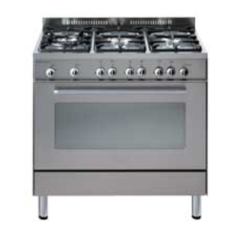
- Page 1 DFG 903 Professional cooker Users Operating Instructions Before operating this cooker, please read these instructions carefully...
- Page 2 Dear Customer Thank you for choosing one of our appliances which has been carefully designed and built by our specialist staff and thoroughly tested to satisfy your cooking requirement. We suggest that you read this Instruction Booklet so that you will understand fully how to operate the appliances.
-
Page 3: Table Of Contents
Contents Model DFG 903 Page Number Introduction ........... . . 4 Assembling the backguard . -
Page 4: Introduction
Introduction Congratulations on your purchase of this Delonghi gas cooker which has been carefully designed and produced to give you many years of satisfactory use. Before using this appliance it is essential that the following instructions are carefully read and fully understood. -
Page 5: Features And Technical Data
Features and technical data Gas burners Gas oven 1. Triple-ring burner (TC) 3,50 kW – Oven burner 6,20 kW 2. Semi-rapid burner (SR) 1,75 kW – Grill burner 4,65 kW 3. Rapid burner (R) 3,00 kW – Oven lamp 15 W 4. -
Page 6: Control Panel
Control panel Fig. 3 CONTROL PANEL - Controls description 1. Gas oven / gas grill control knob 2. Minute counter 3. Front left burner control knob 4. Rear left burner control knob 5. Front central burner control knob 6. Rear central burner control knob 7. -
Page 7: Minute Counter
Minute counter Minute counter The minute counter is a timed acoustic warning device which can be set for a maximum of 60 minutes. The knob (Fig. 4) must be rotated clockwise as far as the 60 minute position and then set to the required time by rotating it anticlockwise. -
Page 8: How To Use The Hob Burners
How to use the hob burners Hob burners Each hob burner is controlled by a separate gas tap operated by a control knob (fig. 5) which has 3 positions marked on the control panel, these are: – Symbol : tap closed (burner off) –... - Page 9 Choice of burner The burner must be choosen according to the diameter of the pans and energy required. Fig. 6a Burners Pan diameter Auxiliary 12 ÷ 14 cm Semi-rapid 16 ÷ 24 cm Rapid 24 ÷ 24 cm Triple-ring 26 ÷ 28 cm do not use pans with concave or convex bases Saucepans with handles which are excessively heavy, in relationship to the weight of the pan, are safer as they are less likely to tip.
- Page 10 Correct use of the triple-ring burner The flat-bottomed pans are to be placed directly onto the pan-support. To use the WOK you need to place the proper stand in order to avoid any faulty operation of the triple-ring burner (Fig. 7a - 7b). CORRECT WRONG Fig.
-
Page 11: How To Use The Gas Oven
How to use the gas oven Lighting the oven gas burner The thermostat allows the automatic control of the temperature. The gas delivery to the oven burner is controlled by a two way thermostatic tap (oven and grill burners) with flame-failure device. To light the oven burner operate as follow: 1) Open the oven door 2) Lightly press and turn the thermostat knob anti-clockwise to max position “... - Page 12 Oven cooking temperatures APPROX. HEAT OF TYPE OF DISH TO COOK MARK TEMP. OVEN 150°C Very cool Meringue cakes, oven slow cooking items • 165°C Cool or Milk puddings, very rich fruit slow oven cakes, i.e., Christmas 180°C Cool or Stews, casseroles, braising, slow oven rich fruit cakes, i.e., Dundee...
-
Page 13: How To Use The Grill
How to use the gas grill Lighting the grill gas burner Do not grill with oven door closed. Always fit the heat shield supplied with the cooker under the front panel before commencing operations (Fig. 12). WARNING. The heat shield and the oven door reaches a very high temperature whilst in use. -
Page 14: Oven Light
Notes: – The grill burner has only one setting, that is full-on – It is important that the heat shield is fitted the correct way up, as shown in the figure 12. Fig. 12 IMPORTANT WARNING For best results when using the grill, place the shelf on the second level and when using the grill pan handle avoid contact with the heat shield which will be HOT during use Oven light... -
Page 15: Important Notes
Important notes Installation, and any demonstration, information or adjustments are not included in the warranty. The cooker must be installed by a qualified person in accordance with the Gas Safety (Installation and Use) (Amendment) Regulations 1990 and the relevant building/l.E.E Regulations. -
Page 16: Do's And Do Not's
Do’s and do not’s Do’s and do not’s • Do always grill with the oven door ajar and with heat baffle mounted. • Do read the user instructions carefully before using the cooker for first time. • Do allow the oven to heat for one and a half hours, before using for the first time, in order to expel any smell from the new oven insulation, without the introduction of food. -
Page 17: Care And Maintenance
Care and maintenance Important: As a safety measure, before you start cleaning the cooker be sure to disconnect it from the mains supply. Do not use a steam cleaner because the moisture can get into the appliance thus make it unsafe. Cleaning the hob Spillage on the hob can usually be removed by a damp soapy cloth. - Page 18 Burners They can be removed and washed only with soapy water. Detergents can be used but must not be abrasive or corrosive. Do not use abrasive sponges or pads. Do not put in dishwasher. After each cleaning, make sure that the burner- caps, as well as the burners, have been well wiped off and CORRECTLY POSITIONED.
-
Page 19: Storage Compartment
Removal of the inner glass door panel The inner glass door panel can easily be removed for cleaning by unscrewing – the four screws (fig. 17). When re-assembly ensure that the inner glass is correctly positioned and do not – over tighten the screws. - Page 20 Assembling and removing the side racks Hang up the wires racks on the oven walls (fig. 19) Slide the required grid or tray into the guides (fig. 20). Fig. 19 Fig. 20 Oven floor The oven floor “F” (fig. 21) can be easily removed to facilitate cleaning. Remember to replace the floor correctly afterwards.
- Page 21 Removing the oven door Fig. 22a Please operate as follows: Open the door completely. The swivel retainers of the rh and lh hinges (fig. 22a) are hooked onto the metal bar above them (fig. 22b). Lift the oven door slightly. The noch on the bottom of the hinge will disengage (fig.
-
Page 22: For The Installer
FOR THE INSTALLER Location This cookers has class “2/1” overheating protection so that it can be installed next to a cabinet. If the cooker is installed adjacent to furniture which is higher than the gas hob cooktop, a gap of at least 50 mm must be left between the side of the cooker and the furniture. The furniture walls adjacent to the cooker must be made of material resistant to heat. -
Page 23: Fitting The Adjustable Feet
Fitting the adjustable feet The adjustable feet must be fitted to the base of the cooker before use. Rest the rear of the cooker an a piece of the polystyrene packaging exposing the base for the fitting of the feet. WARNING Fig. -
Page 24: Stability Bracket
Stability bracket We recommend a stability bracket is fitted to the cooker. The type shown in fig. 29 can be purchased from most plumbers merchants and do it yourself (D.I.Y.) shops. Existing slot in rear of cooker Brackets Fig. 29 Dotted line showing the position of cooker when fixed Outline of cooker... -
Page 25: Provision For Ventilation
Provison for ventilation The room containing the cooker should have an air supply in accordance with BS.5540: Part 2: 1989. All rooms require an openable window or equivalent while some rooms require a permanent vent in addition to the openable window. The cooker should not be installed in a bed-sitting room, of volume less than 21 m Where a DOMESTIC COOKER is installed in a room or internal space, that room or internal space shall be provided with a permanent opening which communicates directly with... -
Page 26: Gas Installation
Gas installation IMPORTANT NOTE This appliance is supplied for use on NATURAL GAS only and cannot be used on any other gas without modification. This appliance is manufactured for conversion to LPG and is supplied with a conversion kit. The cooker must be installed by a qualified person in accordance with the Gas Safety (Installation and Use) (Amendment) Regulation 1990 and the relevant building/l.E.E. - Page 27 Installation to LP Gas This appliance must only be connected to LPG after an LPG conversion kit has been fitted, (see pages from 28 to 33). When operating on Butane gas a supply pressure of 28-30 mbar is required. When using Propane gas a supply pressure of 37 mbar is required. The installation must conform to the relevant British Standards.
-
Page 28: Conversion To Lpg
Conversion to LPG Injectors replacement of top burners Every cooker is provided with a set of injectors for the various types of gas. Injectors not supplied can be obtained from the After-Sales Service. Select the injectors to be replaced according to the table at page 29. The nozzle diameters, expressed in hundredths of a millimetre, are marked on the body of each injector. - Page 29 Table for the choice of the injectors Cat: 2H3+ G 30 - 28-30 mbar G 20 Nominal Reduced BURNERS G 31 - 37 mbar 20 mbar Power Power Ø injector By-pass Ø injector By-pass Ring opening Ring opening [kW] [kW] [mm] [1/100 mm] [1/100 mm]...
- Page 30 Replacement of the oven burner injector According to the type of gas, the oven injector must be similarly replaced, as stated on the “Table for the choice of the injectors”, operating as follows: – remove the oven bottom – unscrew the burner fixing screw (Fig. 35) –...
- Page 31 Replacement of the grill burner injector – Remove the grill burner by unscrewing the front screw (fig. 36). – Gently suspend the burner as shown in figure 37. Take care not to damage the wire to the ignition electrode and the safety valve probe. –...
- Page 32 Fig. 38 Primary air of the oven burner With a screwdriver untighten the screw (fig. 38) and move the air ring forward or back- ward to close or open the air flow, according to the “Table for the choice of the injectors”. Light the burner and check the flames.
-
Page 33: Lubrication Of The Gas Taps
Regulating of the oven minimum To be effected only for the oven burner (as the grill burner has an only fixed input) operating on the thermostat as follows: – Light the oven taking the knob to Max. position. – remove the knob and by a thin screwdriver (3 mm section - 100 mm long) unscrew of about a half turn the screw by-pass, passing through the front panel hole (fig. -
Page 34: Electrical Installation
Electrical installation For your safety please read the following information: This appliance must be installed by a qualified technician according with the current local regulations and in compliance with the manufacturer instructions. This appliance is supplied with a moulded 13 amp three pin mains plug with a 3 amp fuse fitted. - Page 35 A properly earthed three pin plug (fused at 3 amps, to BS 1362 ASTA approved) must be used. As the colours of the wires in the mains lead of this appliance may not correspond with the coloured markings identifying the terminals in your plug, proceed as follows.
- Page 36 DFG 903 cooker Cod. 1101820 ß9...
Need help?
Do you have a question about the DFG 903 and is the answer not in the manual?
Questions and answers