Sign In
Upload
Download
Table of Contents
Contents
Add to my manuals
Delete from my manuals
Share
URL of this page:
HTML Link:
Bookmark this page
Add
Manual will be automatically added to "My Manuals"
Print this page
×
Bookmark added
×
Added to my manuals
Manuals
Brands
DeLonghi Manuals
Cookers
DEF908S
Installation and service instructions manual
DeLonghi DEF908S Installation And Service Instructions Manual
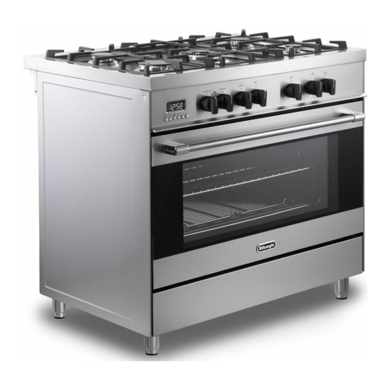
Dual fuel cooker
Hide thumbs
1
2
3
4
5
6
7
8
9
10
11
12
13
14
15
16
17
18
19
20
21
22
23
24
25
26
27
28
29
30
31
32
33
34
35
36
37
38
39
40
41
42
43
44
45
46
47
48
Table Of Contents
49
page
of
49
Go
/
49
Contents
Table of Contents
Bookmarks
Table of Contents
Product Label
Important Safety Precautions and Recommendations
Installation
Electrical Requirements
Fitting the Adjustable Feet
Levelling the Cooker
Anti-Tilt Bracket
Gas Supply
Natural Gas
Control Panel
Gas Burners
General Features
Operating Principles
Thermostat Knob
Function Selector Knob
Oven Light
Cooking Advice
Oven Cooking
Use of the Grill
Electronic Clock
Electronic Timer
Automatic Oven Cooking
Semi-Automatic Cooking
Cleaning and Maintenance
General Advice
Enamelled Parts
Oven Floor
Replacing the Oven Light
Storage Compartment
Removing the Oven Door
Service and Maintenance
Servicing the Appliance
Electric Diagram
Electric Diagram Key
Advertisement
Quick Links
1
Installation
2
Gas Supply
3
Control Panel
4
General Features
5
Function Selector Knob
6
Service and Maintenance
7
Electric Diagram
Download this manual
D E' LO N G H I
C OO KIN G
INSTALLATION and SERVICE INSTRUCTIONS
USE and CARE INSTRUCTIONS
D EF9 08S
D EF9 08A
D UAL F U EL C OO K ER
distributed by
ELBA Appliances Australia
(a Division of Fisher&Paykel Australia)
Table of
Contents
Previous
Page
Next
Page
1
2
3
4
5
Advertisement
Table of Contents
Need help?
Do you have a question about the DEF908S and is the answer not in the manual?
Ask a question
Questions and answers
Related Manuals for DeLonghi DEF908S
Cookers DeLonghi DEF905E Installation And Service Instructions Manual
Delonghi def905e ceramic cooker installation, service, use and care instructions (45 pages)
Cookers DeLonghi DE 61 GW Installation And Service Instructions Use And Care Instructions
Dual fuel cooker (37 pages)
Cookers DeLonghi DEF905GEG Owner's Manual
Dual fuel cooker (53 pages)
Cookers DeLonghi DE 926 GWF Installation And Service Instructions Use And Care Instructions
Dual fuel cooker use and care instructions (49 pages)
Cookers DeLonghi DEFL605G Installation And Service Instructions Manual
Dual fuel cooker (49 pages)
Cookers DeLonghi DEF908A Installation And Service Instructions Manual
Dual fuel cooker (49 pages)
Cookers DeLonghi DEMX 664 IN Quick Start Manual
(4 pages)
Cookers DeLonghi DEF1407A Instruction Manual
Dual fuel cooker (49 pages)
Cookers DeLonghi DEF1407S Instruction Manual
Dual fuel cooker (49 pages)
Cookers DeLonghi DEMX 9642 B Manual
(5 pages)
Cookers DeLonghi DEF1407INDSS Installation And Service & Use And Care Instructions
(57 pages)
Cookers DeLonghi D926GWF Installation And Service Instructions Use And Care Instructions
Dual fuel cooker (49 pages)
Cookers DeLonghi DRS 900-G User & Installation Instructions Manual
(44 pages)
Cookers DeLonghi D 90 G Installation And Service Instructions Manual
Professional cooker (41 pages)
Cookers DeLonghi DFS 090 SO User Operating Instructions Manual
Delonghi dual fuel cooker (37 pages)
Cookers DeLonghi D 926 GII Installation And Service Instructions Manual
Dual fuel cooker (49 pages)
This manual is also suitable for:
Def908a
Table of Contents
Print
Rename the bookmark
Delete bookmark?
Delete from my manuals?
Login
Sign In
OR
Sign in with Facebook
Sign in with Google
Upload manual
Upload from disk
Upload from URL


Need help?
Do you have a question about the DEF908S and is the answer not in the manual?
Questions and answers