
Related Manuals for DeLonghi DFG 905


Summary of Contents for DeLonghi DFG 905
- Page 1 Users Operating Instructions Before operating this oven, please read these instructions carefully DFG 905 Gas Cooker...
- Page 2 Introduction Congratulations on your purchase of this Delonghi gas cooker which has been carefully designed and produced to give you many years of satisfactory use. Before using this appliance it is essential that the following instructions are carefully read and fully understood.
- Page 3 IMPORTANT PRECAUTIONS AND RECOMMENDATIONS After having unpacked the appliance, check to ensure that it is not damaged. In case of doubt, do not use it and consult your supplier or a professionally qualified techni- cian. Packing elements (i.e. plastic bags, polystyrene foam, nails, packing straps, etc.) should not be left around within easy reach of children, as these may cause serious injuries.
-
Page 4: Features And Technical Data
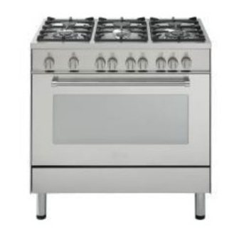
Features and technical data Fig. 1.1 Gas burners 1. Auxiliary burner (A) 1,00 kW 2. Semi-rapid burner (SR) 1,75 kW 3. Rapid burner (R) 3,00 kW 4. Triple-ring burner (TC) 3,50 kW NOTE: The electric ignition is incorporated in the knobs... -
Page 5: Control Panel
Control panel Fig. 2.1 CONTROL PANEL - Controls description 1. Gas oven / gas grill control knob 2. Minute counter 3. Front left burner control knob 4. Rear left burner control knob 5. Front central burner control knob 6. Rear central burner control knob 7. -
Page 6: Minute Counter
Minute counter Minute counter The minute counter is a timed acoustic warning device which can be set for a maximum of 60 minutes. The knob (Fig. 3.1) must be rotated clockwise as far as the 60 minute position and then set to the required time by rotating it anticlockwise. Fig. -
Page 7: How To Use The Hob Burners
How to use the hob burners Hob burners Each hob burner is controlled by a separate gas tap operated by a control knob (fig. 4.1) which has 3 positions marked on the knob itself, these are: – Symbol : tap closed (burner off) –... - Page 8 Choice of burner The burner must be choosen according to the diameter of the pans and energy required. Fig. 4.2 Burners Pan diameter Auxiliary 12 ÷ 14 cm Semi-rapid 16 ÷ 24 cm Rapid 24 ÷ 26 cm Triple-ring 26 ÷ 28 cm do not use pans with concave or convex bases Saucepans with handles which are excessively heavy, in relationship to the weight of the pan, are safer as they are less likely to tip.
- Page 9 Correct use of the triple-ring burner The flat-bottomed pans are to be placed directly onto the pan-support. To use the WOK you need to place the proper stand in order to avoid any faulty operation of the triple-ring burner (Fig. 4.3a - 4.3b). IMPORTANT: The special grille for wok pans (fig.
-
Page 10: How To Use The Gas Oven
How to use the gas oven General features Attention: the oven door becomes very hot during operation. Keep children away. The oven is supplied completely clean; it is advisable, however, upon first use, to turn the oven on to the maximum temperature (position ) to eliminate possible traces of grease from the oven burner. -
Page 11: Lighting The Oven Gas Burner
Lighting the oven gas burner To ignite the oven burner: 1 – Open the oven door to its full extent. WARNING: Risk of explosion! The oven door must be open during this operation. 2 – Lightly press and turn the temperature knob anti-clockwise to max position “ ”... -
Page 12: How To Use The Gas Grill
How to use the gas grill Lighting the grill gas burner Do not grill with oven door closed. Always fit the heat shield supplied with the cooker under the front panel before commencing operations (Fig. 5.5). WARNING. The heat shield and the oven door reaches a very high temperature whilst in use. -
Page 13: Use Of The Grill
The oven door must always be kept half-open when the grill is in operation. See spe- cific instructions in ‘USE OF THE GRILL’. If the flame extinguishes for any reason, the safety valve will automatically shut off the gas supply to the burner. To re-light the burner, first turn the oven control knob to position , wait for at least 1 minute and then repeat the lighting procedure. -
Page 14: Oven Light
Oven light The cooker is equipped with a light that illuminates the oven to enable visually controlling the food that is cooking. This light is controlled by a switch knob (fig. 5.6). Fig. 5.6... -
Page 15: Cooking Guide
Cooking guide Temperature and times given are approximate, as they will vary depending on the quality and amount of food being cooked. Remember to use ovenproof dishes and to adjust the oven temperature during cooking if necessary. Oven cooking temperatures APPROX. -
Page 16: Important Notes
Important notes Installation, and any demonstration, information or adjustments are not included in the warranty. The cooker must be installed by a qualified person in accordance with the Gas Safety (Installation and Use) (Amendment) Regulations 1990 and the relevant building/l.E.E Regulations. -
Page 17: Do's And Do Not's
Do’s and do not’s Do’s and do not’s • Do always grill with the oven door ajar and with heat baffle mounted. • Do read the user instructions carefully before using the cooker for first time. • Do allow the oven to heat for one and a half hours, before using for the first time, in order to expel any smell from the new oven insulation, without the introduction of food. -
Page 18: Care And Maintenance
Care and maintenance Important: As a safety measure, before you start cleaning the cooker be sure to disconnect it from the mains supply. Do not use a steam cleaner because the moisture can get into the appliance thus make it unsafe. Cleaning the hob Spillage on the hob can usually be removed by a damp soapy cloth. - Page 19 Burners They can be removed and washed with soapy water only. They will remain always perfect if cleaned with products used for silverware. After cleaning or wash, check that burner-caps and burner-heads are dry before placing them in the respective housings. It is very important to check that the burner flame distributor and the cap has been correctly positioned - failure to do so can cause serious problems.
-
Page 20: Changing The Oven Light
Triple ring burner The triple ring burner must be correctly positioned (see fig. 6.3); the burner rib must be enter in their logement as shown by the arrow. The burner correctly positioned must not rotate (fig. 6.4). Then position the cap A and the ring B (fig. 6.4). Fig. -
Page 21: Storage Compartment
Removal of the inner glass door panel The inner glass door panel can easily be removed for cleaning by unscrewing – the four screws (fig. 6.5). When re-assembly ensure that the inner glass is correctly positioned and do not – over tighten the screws. -
Page 22: Oven Floor
Assembling and removing the side racks Hang up the wires racks on the oven walls (fig. 6.7) Slide the required grid or tray into the guides (fig. 6.8). Fig. 6.7 Fig. 6.8 Oven floor The oven floor “F” (fig. 21) can be easily removed to facilitate cleaning. Remember to replace the floor correctly afterwards. -
Page 23: Removing The Oven Door
Removing the oven door Fig. 6.10a Please operate as follows: Open the door completely. The swivel retainers of the rh and lh hinges (fig. 6.10a) are hooked onto the metal bar above them (fig. 6.10b). Lift the oven door slightly. The noch on the bottom of the hinge will disengage (fig. -
Page 24: For The Installer
FOR THE INSTALLER Location This cookers has class “2/1” overheating protection so that it can be installed next to a cabinet. If the cooker is installed adjacent to furniture which is higher than the gas hob cooktop, a gap of at least 200 mm must be left between the side of the cooker and the furniture. The furniture walls adjacent to the cooker must be made of material resistant to heat. -
Page 25: Fitting The Adjustable Feet
Fitting the adjustable feet The adjustable feet must be fitted to the base of the cooker before use. Rest the rear of the cooker an a piece of the polystyrene packaging exposing the base for the fitting of the feet. WARNING Fig. - Page 26 We recommend a stability bracket is fitted to the cooker. The type shown in fig. 7.7 can be purchased from most plumbers merchants and do it yourself (D.I.Y.) shops. Existing slot in rear of cooker Brackets Fig. 7.7 Dotted line showing the position of cooker when fixed Outline of cooker backplate at the...
- Page 27 Provison for ventilation The room containing the cooker should have an air supply in accordance with BS.5540: Part 2: 1989. All rooms require an openable window or equivalent while some rooms require a permanent vent in addition to the openable window. The cooker should not be installed in a bed-sitting room, of volume less than 21 m Where a DOMESTIC COOKER is installed in a room or internal space, that room or internal space shall be provided with a permanent opening which communicates directly with...
-
Page 28: Gas Installation
Gas installation IMPORTANT NOTE This appliance is supplied for use on NATURAL GAS only and cannot be used on any other gas without modification. This appliance is manufactured for conversion to LPG and is supplied with a conversion kit. The cooker must be installed by a qualified person in accordance with the Gas Safety (Installation and Use) (Amendment) Regulation 1990 and the relevant building/l.E.E. - Page 29 Installation to LP Gas This appliance must only be connected to LPG after an LPG conversion kit has been fitted, (see pages from 30 to 35). When operating on Butane gas a supply pressure of 28-30 mbar is required. When using Propane gas a supply pressure of 37 mbar is required. The installation must conform to the relevant British Standards.
-
Page 30: Conversion To Lpg
Conversion to LPG Injectors replacement of top burners Every cooker is provided with a set of injectors for the various types of gas. Injectors not supplied can be obtained from the After-Sales Service. Select the injectors to be replaced according to the table at page 31. The nozzle diameters, expressed in hundredths of a millimetre, are marked on the body of each injector. - Page 31 Table for the choice of the injectors Cat: 2H3+ G 30 - 28-30 mbar G 20 Nominal Reduced BURNERS G 31 - 37 mbar 20 mbar Power Power Ø injector Ø injector Ring opening [mm] Ring opening [mm] [kW] [kW] [1/100 mm] [1/100 mm] 1,00...
-
Page 32: Replacement Of The Oven Burner Injector
Replacement of the oven burner injector According to the type of gas, the oven injector must be similarly replaced, as stated on the “Table for the choice of the injectors”, operating as follows: – remove the oven bottom – unscrew the burner fixing screw (Fig. 8.5) –... -
Page 33: Replacement Of The Grill Burner Injector
Replacement of the grill burner injector – Remove the grill burner by unscrewing the front screw (fig. 8.7). – Gently suspend the burner as shown in figure 8.8. Take care not to damage the wire to the ignition electrode and the safety valve probe. –... -
Page 34: Primary Air Of The Oven Burner
Fig. 8.9 Primary air of the oven burner With a screwdriver untighten the screw (fig. 8.9) and move the air ring forward or back- ward to close or open the air flow, according to the “Table for the choice of the injectors”. Light the burner and check the flames. -
Page 35: Regulating Of The Oven Minimum
Regulating of the oven minimum To be effected only for the oven burner (as the grill burner has an only fixed input) operating on the thermostat as follows: – Light the oven taking the knob to Max. position. – remove the knob and by a thin screwdriver (3 mm section - 100 mm long) unscrew of about a half turn the screw by-pass, passing through the front panel hole (fig. -
Page 36: Electrical Installation
Electrical installation For your safety please read the following information: This appliance must be installed by a qualified technician according with the current local regulations and in compliance with the manufacturer instructions. This appliance is supplied with a moulded 13 amp three pin mains plug with a 3 amp fuse fitted. - Page 37 A properly earthed three pin plug (fused at 3 amps, to BS 1362 ASTA approved) must be used. As the colours of the wires in the mains lead of this appliance may not correspond with the coloured markings identifying the terminals in your plug, proceed as follows.
- Page 39 Descriptions and illustrations in this booklet are given as simply indicative. The manufacturer reserves the right, considering the characteristics of the models described here, at any time and without notice, to make eventual necessary modifications for their construction or for commercial needs.
- Page 40 cod. 1102425 ß4...
Need help?
Do you have a question about the DFG 905 and is the answer not in the manual?
Questions and answers