
Related Manuals for DeLonghi DSR 916-GS


Summary of Contents for DeLonghi DSR 916-GS
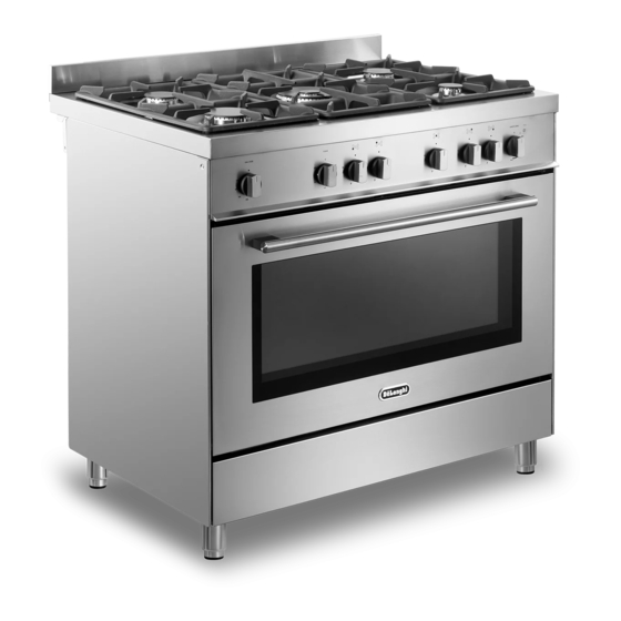
- Page 1 DE ’ L O NG H I COOK IN G INSTALLATION & USER INSTRUCTIONS DSR 916-GS G AS C OOK E R S...
-
Page 2: Table Of Contents
CONTENTS Page Number Introduction....................3 Important Safeguards & Recommendations........... 4-9 Advice for the installer Installation....................11-16 Gas installation..................17-25 Electrical section..................26-27 Advice for the user Cooking Hob.................... 29 Control Panel................... 30 Use of the Hob Burners................31-33 Gas Oven....................34-37 Oven temperature guide................ -
Page 3: Introduction
Dear Customer, Thank you for purchasing a De’Longhi DSR 916-GS, gas cooker. The safety precautions and recommendations reported below are for your own safety and that of others. They will also provide a means by which to make full use of the features offered by your appliance. -
Page 4: Important Safeguards & Recommendations
IMPORTANT SAFETY PRECAUTIONS AND RECOMMENDATIONS IMPORTANT: This appliance is designed and manufactured solely for the cooking of domestic (household) food and is not suitable for any non domestic application and therefore should not be used in a commercial environment. The appliance guarantee will be void if the appliance is used within a non domestic environment i.e. - Page 5 • CAUTION: this appIiance must only be installed in a permanently ventilated room in compliance with the applicable regulations. • Do not operate your appliance by means of an external timer or separate remote-control system. • Do not carry out cleaning or maintenance operations on the appliance without having previously disconnected it from the electric power supply.
- Page 6 • WARNING: During use the appliance and its accessible parts become hot; they remain hot for some time after use. Care should be taken to avoid touching heating elements (on – the hob and inside the oven). The door is hot, use the handle. –...
- Page 7 • Do not line the oven walls or base with aluminium foil. Do not place baking trays or the drip tray on the base of the oven chamber. • Do not cover the hob with aluminium foils. • storage compartment. •...
- Page 8 • WARNING: The appliance and its accessible parts become hot during use. Care should be taken to avoid touching heating elements. Children less than 8 years of age shall be kept away unless continuously supervised. • WARNING: Use only hob guards designed by the manufacturer of the cooking appliance or indicated by the manufacturer of the appliance in the instructions for use as suitable or hob guards incorporated in the appliance.
- Page 9 ENERGY LABELLING/ECODESIGN • Commission delegated regulation (EU) No 65/2014 (supplementing Directive 2010/30/EU of the European Parliament and of the Council). • Commission regulation (EU) No 66/2014 (implementing Directive 2009/125/EC of the European Parliament and of the Council). Reference to the measurement and calculation methods used to establish compliance with the above requirements: •...
-
Page 10: Advice For The Installer
Advice for the installer... -
Page 11: Installation
1 - INSTALLATION IMPORTANT • The appliance is designed and approved for domestic use only and should not be installed in a commercial, semi commercial or communal environment. Your product will not be guaranteed if installed in any of the above environments and could affect any third party or public liability insurances you may have. - Page 12 This cooker has class “2/1” overheating protection so that it can be installed next to a cabinet. If the cooker is installed adjacent to furniture which is higher than the gas hob cooktop, a gap of at least 200 mm must be left between the side of the cooker and the furniture. material.
- Page 13 FITTING THE ADJUSTABLE FEET Rest the rear of the cooker on a piece of the polystyrene packaging exposing the Fit the 4 legs by screwing them tight into LEVELLING THE COOKER Fig. 1.2 The cooker may be levelled by screwing 1.4).
- Page 14 MOVING THE COOKER WARNING: When raising cooker to upright position always ensure two people carry Fig. 1.6 WARNING WARNING Be carefull: Do not lift the cooker by the door handle/s when raising to the Fig. 1.8 Fig. 1.7...
- Page 15 ANTI-TILT BRACKET Important! After you have located where the cooker is to be positioned, mark on the wall the place Drill two 8 mm diameter holes in the wall and insert the plastic plugs supplied. Important! Before drilling the holes, check that you will not damage any pipes or electrical wires.
- Page 16 PROVISION FOR VENTILATION • The appliance should be installed into a room or space with an air supply in accordance with the current version of BS 5440-2: 2000. • For rooms with a volume of less than 5m - permanent ventilation of 100 cm free area must be provided.
-
Page 17: Gas Installation
2 - GAS INSTALLATION IMPORTANT NOTE This appliance is supplied for use on NATURAL GAS or LPG (check the gas regulation label attached on the appliance). • Appliances supplied for use on NATURAL GAS are adjusted for this gas only and manufactured for conversion to LPG. - Page 18 RESTRAINING CHAIN Fig. 2.1 Chain security holes Cooker Back of the cooker Rear wall Installation to Natural Gas Installation to Natural Gas must conform to the Code of Practice, etc. The supply pressure for Natural Gas is 20 mbar. The installation must conform to the relevant British/European Standards. Installation to LP Gas When operating on Butane gas a supply pressure of 28-30 mbar is required.
- Page 19 Notes: • Flexible hoses can be used where the sited ambient temperature of the hose being used. • Gas hoses designed for natural gas MUST NOT be used for supplying LPG gas outer coating of the hose). The hose should not be crushed or trapped or be in contact with sharp or abrasive edges.
- Page 20 Fitting the plug Fig. 2.3 on the inlet pipe terminal not used Cooker manifold (right Cooker or left inlet pipe) manifold (right or left inlet pipe) Manifold male Manifold male 1/2” G cylindrical (ISO 228-1) male 1/2” G cylindrical (ISO 228-1) male Fibre Fibre washer ( * )
- Page 21 CONVERSION TO NATURAL GAS OR TO LPG REPLACEMENT OF THE INJECTORS Auxiliary, If the injectors are not supplied they can Semi-rapid and be obtained from the After-Sales Service. Rapid burners Select the injectors to be replaced according to the “Table for the choice of the injectors”.
- Page 22 TABLE FOR THE CHOICE OF THE INJECTORS Cat: 2H3+ Natural Gas G30 28-30 mbar G20 20 mbar Nominal Reduced G31 37 mbar power power Ø Air ring Ø Air ring [kW] [kW] BURNERS injector opening injector opening [1/100 mm] [mm] [1/100 mm] [mm] Auxiliary (A)
- Page 23 OPERATIONS TO BE EXECUTED FOR THE REPLACEMENT OF THE INJECTORS OF THE OVEN AND GRILL BURNER a) oven burner • Lift and remove the lower panel inside the oven. • Unscrew and remove the burner securing screw “A • Slacken screw “B Fig.
- Page 24 Fig. 2.8 REGULATION OF AIR SUPPLY TO OVEN BURNER Using a cross-head screwdriver, slacken the screw “Q regulation collar “P collar forward or backward to increase or reduce the air aperture in accordance with gas type and the indications in the ‘Table for the choice of the injectors’.
- Page 25 ADJUSTMENT OVEN Flame faulty Flame with Flame BURNER MINIMUM in primary excess correct primary air Considering that in the minimum position short and sharp long, yellow clear interior too blue interior and must remain lit even with a brusque and trembling blue cone cone tending to passage from the maximum position to that...
-
Page 26: Electrical Section
3 - ELECTRICAL INSTALLATION IMPORTANT: The cooker must be installed in accordance with the manufacturer’s instructions. Incorrect installation, for which the manufacturer accepts no responsibility, may cause damage to persons, animals and things. The connection of the appliance to earth is mandatory. The manufacturer declines all responsability for any inconvenience resulting from the inobservance of this condition. - Page 27 ELECTRICAL FEEDER CABLE REPLACEMENT WARNING: If the power supply cable is damaged, it must be replaced only by an authorised service agent in order to avoid a hazard. To connect the supply cable: • Remove the screw securing the cover “A •...
-
Page 28: Advice For The User
Advice for the user... -
Page 29: Cooking Hob
1 - COOKING HOB Fig. 1.1 GAS BURNERS 1. Auxiliary burner (A) 1,00 kW 2. Semi-rapid burner (SR) 1,75 kW 3. Rapid burner (R) 3,00 kW 4. Double-ring compact burner (DCC) 4,00 kW Notes: • The electric ignition is incorporated in the knobs. •... -
Page 30: Control Panel
2 - CONTROL PANEL Fig. 2.1 CONTROLS DESCRIPTION Front right burner control knob Rear right burner control knob Central burner control knob Rear left burner control knob Front left burner control knob 120’ alarm knob Gas oven thermostat control knob Electric grill and oven light control knob Line pilot light (electric grill) Please note: This appliance incorporates a safety cooling fan which you will hear operating... -
Page 31: Use Of The Hob Burners
3 - USE OF THE HOB BURNERS GAS BURNERS which control the safety valves. Turning the knob, so that the indicator line points to the symbols printed on the panel, achieves the following functions: - symbol closed valve maximum - symbol minimum Fig. - Page 32 LIGHTING THE BURNERS CHOICE OF THE BURNER ignite burner, following On the control panel, near every knob instructions are to be followed: there is a diagram that indicates which burner is controlled by that knob. Press in the corresponding knob and The suitable burner must be chosen according to the diameter and the capacity used.
- Page 33 CORRECT USE OF THE DOUBLE-RING COMPACT BURNER double-ring compact burner. When using a WOK, the supplied wok stand must be placed onto the pan stand to avoid should not be IMPORTANT: Under no circumstances should the wok stand be placed under the pan supports harmful levels of Carbon Monoxide (CO).
-
Page 34: Gas Oven
4 - GAS OVEN OVEN BURNER WARNING: It carries out normal “oven cooking”. The door is hot, use the handle. During use the appliance becomes a thermostat which allow to maintain the hot. Care should be taken to avoid oven temperature constant. touching heating elements inside the The control of the temperature is assured oven. - Page 35 IGNITION OF THE OVEN BURNER Fig. 4.2 ATTENTION: Never turn the control knob before opening the oven door. To ignite the oven burner: Open the oven door to the full extent. WARNING: Risk of explosion! The oven door must be open during this operation.
- Page 36 ELECTRIC GRILL To switch on the grill turn the control knob clockwise and set the knob to the required For safety reasons, it is not allowed to temperature between minimum use the oven burner and the electric grill together, at the same time. The indicator light close to the control knob The electric grill only operates when is alight when the grill is operating.
- Page 37 COOKING WITH ELECTRIC GRILL KEEP WARM OR SLOW HEATING Switch on the electric grill by turning the Switch on the electric grill. control knob to the maximum position Turn the grill control knob to the minimum with the door closed. The heat is diffused throughout the oven by Introduce the food to be cooked positioning radiation.
-
Page 38: Oven Temperature Guide
5 - OVEN TEMPERATURE GUIDE Electric oven temperature Cooking process Oven heat Gas mark Keeping food hot, very cool ½ milk puddings Egg custards cool Rich fruit cakes, cool braising Low temperature moderate roasting, shortbread plain fruit cake, moderate Small cakes, choux fairly hot pastry Short pastry, Swiss... -
Page 39: 120 Minute Timer
6 - 120 MINUTE TIMER 120 MINUTE TIMER The timer can be set to a maximum of 120 minutes and a buzzer will sound at the end of the countdown. The knob must be rotated clockwise as then set to the required time by rotating it anticlockwise. -
Page 40: Cleaning And Maintenance
GENERAL ADVICE CLEANING • Before you begin cleaning, you • Stainless steel hob: Spillage on must ensure that the appliance is the hob can usually be removed by switched off at the cooker switch. a damp soapy cloth. More obstinate stains can be removed by using a •... - Page 41 • Inside of oven: The oven should BURNERS AND PAN SUPPORTS always be cleaned after use when it These parts must be cleaned using a has cooled down. The cavity should be sponge and soapy water or other suitable cleaned using a mild detergent solution non-abrasive products.
- Page 42 Fig. 7.1 Fig. 7.2 Fig. 7.3 Fig. 7.4 Fig. 7.5...
- Page 43 INSIDE OF OVEN Fig. 7.6 The oven should always be cleaned after use when it has cooled down. The bottom of the oven, side runner frames, tray and rack can be removed and washed. The cavity should be cleaned using a mild detergent solution and warm water.
- Page 44 STORAGE COMPARTMENT REPLACING THE OVEN LAMP The storage compartment is accessible WARNING: Ensure the appliance is switched off and disconnected from the electrical power supply before replacing the lamp to avoid the possibility of electric shock. • Let the oven cavity and the heating oven or in the storage compartment.
- Page 45 REMOVING THE OVEN DOORS The oven door can easily be removed as follows: • 7.11a). • Open the lever “A” completely on the • Fig. 7.11a • Gently close the door (until left and right hinge levers “A” are hooked to part “B”...
- Page 46 REFIT THE DOORS Insert the hinge tongues into the slots, making sure that the groove drops into Open the door to its full extent. Fully close the levers “A” on the left and right hinges, as shown in the Fig. 7.12a Close the door and check that it is properly in place.
-
Page 47: Guarantee
“De’Longhi” product comes with 12-month guarantee covering all parts and labour. If your appliance proves to be defective as a result of faulty materials or workmanship during the guarantee period, these parts will be repaired or replaced free of charge. AFTER SALES SERVICE Should you require service, spares or product information and advice: •... - Page 48 Descriptions and illustrations in this booklet are given as simply indicative. The manufacturer reserves the right, considering the characteristics of the models described here, at any time and without notice, to make eventual necessary modifications for their construction or for commercial needs. w w w.
Need help?
Do you have a question about the DSR 916-GS and is the answer not in the manual?
Questions and answers