
Related Manuals for DeLonghi DE 61 GW


Summary of Contents for DeLonghi DE 61 GW
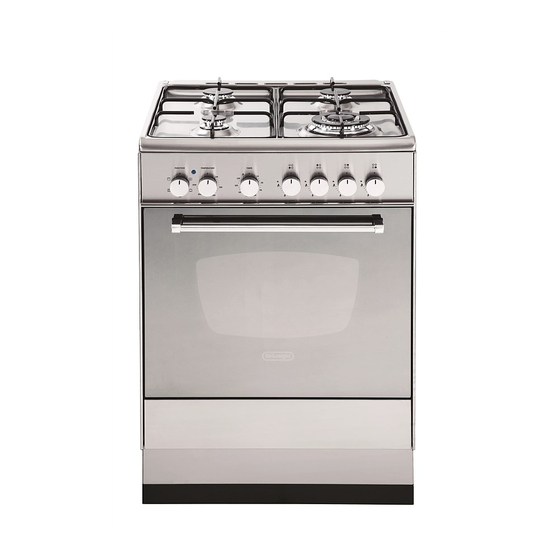
- Page 1 INSTALLATION and SERVICE INSTRUCTIONS USE and CARE INSTRUCTIONS DE 61 GW DUAL FUEL COOKER distributed by DèLonghi Pty Ltd...
-
Page 2: Product Label
Dear Customer, Thank you for having purchased and given your preference to our product. The safety precautions and recommendations reported below are for your own safety and that of others. They will also provide a means by which to make full use of the features offered by your appliance. -
Page 3: Using The Oven For The First Time
USING THE OVEN FOR THE FIRST TIME You are advised to carry out the following operations: ■ Furnish the interior of the oven. ■ Switch the empty oven ON at maximum temperature for about two hours to eliminate traces of grease and smell from the components. ■... -
Page 4: Important Precautions And Recommendations
IMPORTANT PRECAUTIONS AND RECOMMENDATIONS After having unpacked the appliance, check to ensure that it is not damaged. In case of doubt, do not use it and consult your supplier or a professionally qualified technician. Packing elements (i.e. plastic bags, polystyrene foam, nails, packing straps, etc.) should not be left around within easy reach of children, as these may cause serious injuries. -
Page 5: Installation
INSTALLATION CAUTION: ■ This appliance must be installed in accordance with these installation instructions. ■ This appliance shall only be serviced by authorized personnel. ■ This appliance is to be installed only by an authorised person. ■ Incorrect installation, for which the manufacturer accepts no responsibility, may cause personal injury of damage. - Page 6 CLEARANCES Installation clearances and protection of combustible surfaces shall comply with the current local regulations eg. AG 601 (AS 5601) Gas Installations code. Installation shall comply with the dimension in Fig. 1 bearing in mind that. Overhead Clearances In no case shall the clearances between the highest part of the cooker be less than 600 mm or for an overhead exhaust fan 750 mm.
-
Page 7: Levelling The Cooker
LEVELLING THE COOKER The cooker is equipped with 4 levelling feet and may be levelled by screwing or unscrewing the feet with a spanner (fig. 4). It is important to observe the prescriptions of figures 2a, 2b, 3. Figure 2a Figure 3 Figure 2b Supplied with the cooker... -
Page 8: Anti-Tilt Bracket
ANTI-TILT BRACKET Important! To restrain the appliance and prevent it tipping accidentally, the anti-tilt bracket must be fitted according to the instructions below. 1. Drill four 8mm diameter holes for the fixing screws (two in the wall and two in the floor - see Fig. -
Page 9: Gas Supply
GAS SUPPLY: ■ The connection must be performed by an authorised person according to the relevant standards. ■ Before connecting the appliance to the gas main, mount the brass conical adap- tor onto the gas inlet pipe, upon which the gasket has been placed (figs. 6-7). Conical adaptor and gasket are supplied with the appliance (packed with con- version kit for use with Natural gas or ULPG). - Page 10 Customer Service Centre should be called to obtain the nearest authorized Delonghi Service Agent. WARNING, This appliance IS NOT SUITABLE for installation with a hose assembly.
- Page 11 CONVERSION PROCEDURE (to convert to Natural gas or to ULPG) REPLACING THE INJECTORS This appliance is suitable for use with Natural gas or ULPG (check the “gas type” sticker attached to the appliance). A label stating the type of gas used after replacing the injectors must be attached at the rear of the appliance, in proximity of the gas inlet connection.
- Page 12 MINIMUM BURNER SETTING ADJUSTMENT Check whether the flame spreads to all burner ports when the burner is lit with the gas tap set to the minimum position. If some ports do not light, increase the minimum gas rate setting. Check whether the burner remains lit even when the gas tap is turned quickly from the maximum to the minimum position.
-
Page 13: Lubrication Of The Gas Taps
TABLE FOR THE CHOICE OF THE INJECTORS Natural gas ULPG 2.75 Test Point Pressure [kPa] Injector Injector Orifice Dia. Consumption Orifice Dia. Consumption BURNER [mm] [MJ/h] [mm] [MJ/h] Auxiliary (A) 0.85 3.60 0.53 3.60 Semi-rapid (SR) 1.12 6.30 0.70 6.30 Triple ring (TC) 1.65 13.30... -
Page 14: Use And Care
USE and CARE CAUTION: ■ This appliance must be used only for the task it has explicitly been designed for, that is for domestic cooking of foodstuffs. Any other form of usage is to be con- sidered as inappropriate and therefore dangerous. ■... -
Page 15: Grease Filter
USING THE OVEN FOR THE FIRST TIME ■ Clean the inside of the oven with a cloth soaked in water and neutral detergent and dry thoroughly. ■ Slide in the wire racks on the oven wall as in Fig. 14. ■... -
Page 16: Gas Burners
GAS HOB Figure 17 GAS BURNERS Natural Gas ULPG MJ/h MJ/h 1. Auxiliary burner (A) 2. Semi-rapid burner (SR) 3. Semi-rapid burner (SR) 4. Triple ring burner (TC) 13.3 11.9... - Page 17 ■ If the flame is still not correct, turn the burner off and call our Customer Service center for your nearest Authorized Delonghi Service Agent. ■ In the case of a mains failure light the burner with a match or lighted taper.
- Page 18 CHOICE OF BURNER The burner must be chosen according to the diameter of the pans and energy required. For optimum efficiency use a wok or pan no smaller than 230mm diameter. Figure 19 do not use pans with concave or convex bases Burners Pan diameter Auxiliary...
- Page 19 CORRECT USE OF TRIPLE-RING BURNER ■ The flat-bottomed pans are to be placed directly onto the pan-support. ■ To use the WOK, you must place the wok stand in the CORRECT position as shown in Figs. 20-21. IMPORTANT: The special grille for wok pans (fig. 21) MUST BE PLACED ONLY over the pan-rest for the triple-ring burner.
-
Page 20: Control Panel
PLURIFUNCTION ELECTRIC OVEN Figure 22 CONTROL PANEL Controls description 1. Front right burner control knob 2. Rear right burner control knob 3. Rear left burner control knob 4. Front left burner control knob 5. 120’ timer 6. Plurifunction oven thermostat knob 7. -
Page 21: Operating Principles
OPERATING PRINCIPLES Heating and cooking in the fan assisted oven are obtained in the following ways: a. by normal convection The heat is produced by the upper and lower heating elements. b. by forced semi-convection The heat produced by the top and bottom heating elements is distributed through- out the oven by the fan. -
Page 22: Function Selector Knob
FUNCTION SELECTOR KNOB Rotate the knob clockwise to set the oven for one of the following functions. OVEN LIGHT By setting the knob to this position, only the oven light comes on. It remains on in all the cooking modes. TRADITIONAL BAKE The upper and lower heating elements come on. -
Page 23: Fan Grill
FAN GRILL Both the grill and the fan come on. Most of the cooking is done by grilling and then the hot air circulated around the oven. The oven door should be kept closed. The temperature can be set between 50 °C and 175 °C maximum. The oven should be preheated for 5 minutes before cooking. -
Page 24: Cooking Advice
COOKING ADVICE STERILIZATION Sterilization of foods to be conserved, in full and hermetically sealed jars, is done in the following way: a. Set the switch to position b. Set the thermostat knob to position 185 °C and preheat the oven. c. -
Page 25: Grilling And Cooking Au Gratin
GRILLING AND COOKING AU GRATIN As the hot air completely covers the food to be cooked, grilling may be done with the food on rack in the oven. The knob should be switched to position The thermostat should be set to 175 °C and the oven pre-heated. The food should be placed on a rack in the oven for the required cooking time. - Page 26 RECOMMENDED COOKING TEMPERATURE Food °C °F Shelf Cooking Mark Position Time (approx) CAKES Victoria sandwich 2 or 3 20-25 mins Small cakes/buns 1 and 2 15-20 mins Maidera cake 2 or 3 20 mins 3 /4 Fruit cake hours 1 /2 Rich fruit cake 3 or 4 hours...
- Page 27 How to use the timer TIMER (Fig. 24) The timer runs the oven for a preset time. 1) Starting up After setting the function selector and thermostat to the required mode and temper- ature, rotate the timer knob clockwise until you reach the required cooking time (max 120 minutes).
-
Page 28: General Advice
ONLY SOAP/WARM WATER MUST BE USED TO CLEAN THE STAINLESS STEEL SURFACES. GAS TAPS If the gas taps are not working properly, call our Customer Service Centre to obtain the nearest Authorized Delonghi Service Agent. -
Page 29: Replacing The Oven Light Bulb
INSIDE OF OVEN ■ The oven should always be cleaned after use when it has cooled down. The cavity should be cleaned using a mild detergent solution and warm water. Suitable proprietary chemical cleaners may be used after first consulting with the manufacturers recommendations and testing a small sample of the oven cavity. - Page 30 BURNERS Figure 26 They can be removed and washed only with soapy water. Detergents can be used but must not be abrasive or corrosive. Do not use abrasive sponges or pads. Do not put in dishwasher. After cleaning, make sure that the burner-caps, as well as the burners, have been well wiped off and CORRECTLY POSITIONED.
-
Page 31: Removing The Oven Door
Figure 30 REMOVING THE OVEN - Type “A” DOOR The oven door can easily be removed as follows: ■ Open the door to the full extent (fig. 30). ■ Attach the retaining rings to the hooks on the left and right hinges (fig. -
Page 32: Door Assembly
Figure 34 REMOVING THE OVEN DOOR - Type “B” To facilitate oven cleaning, it is possible to remove the door. Please follow the instructions carefully: Open the door completely. Push down the lever “L” (fig. 34) and, keeping it in this position, slowly close the door in order to block the hinge. -
Page 33: Service And Maintenance
Service and Maintenance If the ignition spark fails to ignite or does not light the gas, check the following items before calling our Customer Service Centre to obtain the nearest Authorised Service Agent: ■ Burner is reassembled and located correctly. ■... -
Page 34: Wiring Diagram
WIRING DIAGRAM ELECTRIC DIAGRAM KEY Oven switch Oven thermostat Thermal overload Oven cut off Oven lamp Top element Grill element Bottom element Thermostat pilot lamp Ignition switches group Ignition coil Terminal block Earth connection... - Page 35 Descriptions and illustrations in this booklet are given as simply indicative. The manufacturer reserves the right, considering the characteristics of the models described here, at any time and without notice, to make eventual necessary modifications for their construction or for commercial needs.
- Page 36 cod. 1103185 ß1...
Need help?
Do you have a question about the DE 61 GW and is the answer not in the manual?
Questions and answers