
Related Manuals for DeLonghi D 61 E


Summary of Contents for DeLonghi D 61 E
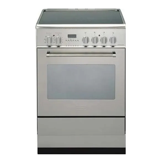
- Page 1 INSTALLATION and SERVICE INSTRUCTIONS USE and CARE INSTRUCTIONS D 61 E CERAMIC COOKER distributed by DèLonghi Pty Ltd...
-
Page 2: Product Label
Dear Customer, Thank you for having purchased and given your preference to our product. The safety precautions and recommendations reported below are for your own safety and that of others. They will also provide a means by which to make full use of the features offered by your appliance. - Page 3 FIRST TIME USE THE OVEN It is advised to follow these instructions: Clean the interior of the oven with cloth soaked in water and detergent (neutral) then dry carefully. Fit the wire racks as described at chapter “Use and care”. Insert shelves and tray.
-
Page 4: Important Precautions And Recommendations
IMPORTANT PRECAUTIONS AND RECOMMENDATIONS After having unpacked the appliance, check to ensure that it is not damaged. In case of doubt, do not use it and consult your supplier or a professionally qualified techni- cian. Packing elements (i.e. plastic bags, polystyrene foam, nails, packing straps, etc.) should not be left around within easy reach of children, as these may cause serious injuries. -
Page 5: Installation
CAUTION: This appliance must be installed in accordance with these installation instructions. This appliance shall only be serviced by authorized personnel. This appliance is to be installed only by an authorised person. Incorrect installation, for which the manufacturer accepts no responsibility, may cause personal injury of damage. - Page 6 The cooker has type “Y” overheating protection so that it can be installed in a cabinet. The cooker must be installed no less than 50 mm away from any side wall which exceed the height of the cooktop; The appliance must be housed in heat resistant units.
-
Page 7: Anti-Tilt Bracket
ANTI-TILT BRACKET Warning: This appliance must be restrained to prevent accidental tipping by fitting a bracket to the rear of the appliance and securely fixing it to the wall. Fixing the anti-tilt bracket: After you have located where the cooker is to be positioned mark, on the wall, the place where the 2 screws of the anti-tilt bracket have to be fitted. -
Page 8: Use And Care
Do NOT spray aerosols in the vicinity of this appliance while it is in use. Before using for the first time, clean the cooktop with warm soapy water. We recommend that you run each plate individually for several minutes. To do this, place a saucepan of cold water on each plate in turn, and bring the water to the boil. -
Page 9: Using The Oven For The First Time
USING THE OVEN FOR THE FIRST TIME Slide off the sliding shelves and the catalytic liners to the oven wall as in Fig. 3A. The grill is secured to the rear wall of the oven on a hinge system that allows it to be lowered to allow proper access when cleaning the oven ceiling (fig. -
Page 10: Cooking Zones
COOKING ZONES 1. Radiant hotplate 2. Radiant hotplate 3. Radiant hotplate 4. Halogen hotplate 5. Residual indicators Attention: Detach the appliance from the mains if the ceramic hob is cracked. The ceramic surface of the hob allows a fast transmission of heat in the vertical direc- tion, from the heating elements underneath the ceramic glass to the pans set upon it. - Page 11 TYPE OF HOTPLATES RADIANT HOTPLATES: Each radiant plate is comprised of the elements which can be controlled either separately or together using the 7 position switches fig. 6. The temperature control knobs must be turned anti clockwise. When a plate is on, the indicator light on the control panel will be lit.
-
Page 12: Halogen Hotplate
HALOGEN HOTPLATE Incorporating 1 halogen lamp and 2 heat- ing elements (fig. 8 - type A or fig. 9-type Instantly reaches the working temperature. Controlled by energy regulator switch. Figure 7 HALOGEN HOTPLATE CONTROL KNOB The halogen hotplate is controlled by a energy regulator switch (fig. -
Page 13: Safety Hints
SAFETY HINTS: 1. Never put cooking foil or plastic materials on the ceramic surface when the hob is hot. 2. Make sure that the hob is clean before you use it. 3. Remember that the plates will remain hot for approximately half an hour after the plate has been switched off. -
Page 14: Residual Heat Indicator
5 or 10 minutes before the end of the cooking. The residual heat of the hob will complete the cooking. – To save electricity, use pan lids whenever possible. – Never cook the food directly on the glass ceramic cooktop, but in special pans or containers. -
Page 15: Cooking Hints
COOKING HINTS: Switch Switch Position Position Halogen Quick-light sta hotplates hotplates 1 - 2 1 - 2 2 - 3 - 4 4 - 5 - 6 3 - 4 6 - 7 7 - 8 4 - 5 8 - 9 - 10 11 - 12 Please note that these are only guidelines, you will quickly learn from experience which setting is correct for your needs. - Page 16 COOKWARE: It is very important that the pans used on the hobs are made of a suitable material and have the correct base as follows: The base should be flat and smooth. Any rough part on the pan base could scratch the hob surface. Choose pans which are the same size as the hotplates and with bases that are as non reflective as possible.
-
Page 17: Multifunction Oven
MULTIFUNCTION OVEN CONTROL PANEL - Controls description 1. Front right hotplate control knob 2. Rear right hotplate control knob 3. Rear left hotplate control knob 4. Front left hotplate control knob 5. Multifunction oven thermostat knob 6. Multifunction oven switch knob 7. -
Page 18: Operating Principles
OPERATING PRINCIPLES Heating and cooking in the MULTI-FUNCTION oven are obtained in the following ways: a. by normal convection The heat is produced by the upper and lower heating elements. b. by forced convection The fan in the oven sucks the air that is contained within the oven housing at the rear of the oven and forced it over the circular heating element.The hot air envelops the food in the oven giving faster and more even cooking before it is sucked back into the housing to repeat the cycle. -
Page 19: Oven Light
OVEN LIGHT By setting the knob to this position, only the oven light comes on (15 W). It remains on in all the cooking modes. TRADITIONAL BAKE The upper and lower heating elements come on. The heat being dispersed by natural convection. -
Page 20: Fan Grill
FAN FORCED The circular element and fan come on. The heat is dispersed by forced convection and the temperature can be varied to between 50° and 250°C via the thermostat knob. The oven does not require preheating. Recommended for: Food which has to be well-cooked outside and soft or rosy inside, for example lasagne, lamb, roast beef, whole fish etc. -
Page 21: Cooking Advice
COOKING ADVICE STERILIZATION Sterilization of foods to be conserved, in full and hermetically sealed jars, is done in the following way: a. Set the switch to position b. Set the thermostat knob to position 185 °C and preheat the oven. c. - Page 22 RECOMMENDED COOKING TEMPERATURE Food CAKES Victoria sandwich Small cakes/buns Maidera cake Fruit cake Rich fruit cake Scones PASTRY Puff Short crust Plate tarts Quiches and flans YEAST Bread loaf Bread rolls Pizza dough ROAST MEAT Beef – Medium Lamb Pork Veal Chicken Turkey up to 10lb...
-
Page 23: Electronic Programmer
ELECTRONIC PROGRAMMER The electronic programmer is a device which groups together the following functions: 24 hours clock with illuminated display Timer (up to 23 hours and 59 minutes) Program for automatic oven cooking Program for semi-automatic oven cooking. Description of the buttons: Timer Cooking time End of cooking time... -
Page 24: Electronic Clock
ELECTRONIC CLOCK The programmer is equipped with an electronic clock with lighted numbers which indicates hours and minutes. Upon immediate connection of the oven or after a power cut, three zeros will flash on the programmer panel. To set the hour it is necessary to push button and then the button until you have set the exact hour (fig. -
Page 25: Automatic Oven Cooking
AUTOMATIC OVEN COOKING To cook food automatically in the oven, it is necessary to: 1.Set the length of the cooking time 2.Set the end of the cooking time 3.Set the temperature and the oven cooking program. These operations are done in the following way: 1.Set the length of the cooking time by pushing the... -
Page 26: Semi - Automatic Cooking
SEMI - AUTOMATIC COOKING This function is only used to set the END of the cooking time of the oven. There are two ways of setting this function. 1. Set the length of the cooking time by pushing the button to advance, or backwards (Fig. -
Page 27: General Advice
Cleaning and Maintenance GENERAL ADVICE Before you begin cleaning, you must ensure that the appliance is switched off. It is advisable to clean when the appliance is cold and especially when cleaning the enamelled parts. Avoid leaving alkaline or acidic substances (lemon juice, vinegar, etc.) on the surfaces. -
Page 28: Enamelled Parts
ENAMELLED PARTS All of the enamelled parts must be washed only with a sponge and soapy water or with non-abrasive products. Dry, preferably, with deer skin. STAINLESS STEEL SURFACE The stainless steel front panels on this cooker (facia, oven door, drawer or storage compartment) are protected by a finger-print proof lacquer. -
Page 29: Replacing The Oven Light
GREASE FILTER Clean the filter after any cooking! The grease filter can be removed for cleaning and should be washed regularly in hot soapy water (fig. 4 at page 4). Always dry the filter properly before fitting it back into the oven. OVEN DOOR AND DRAWER The internal glass of the oven door can be easily removed for cleaning by unscrewing the two lateral fixing screws (fig. - Page 30 REMOVING THE OVEN DOOR - Type “A” The oven door can easily be removed as follows: Open the door to the full extent (fig. 24). Attach the retaining rings to the hooks on the left and right hinges (fig. 25). Hold the door as shown in fig.
-
Page 31: Door Assembly
REMOVING THE OVEN DOOR - Type “B” To facilitate oven cleaning, it is possible to remove the door. Please follow the instructions carefully: Open the door completely. Push down the lever “L” (fig. 28) and, keeping it in this position, slowly close the door in order to block the hinge. - Page 32 LEVELLING The cooker is equipped with a 4 levelling feet which must be fitted to the base of the cooker in the following manner: – Place the cooker on its back as shown in the figure 31. – Screw the 4 leveling feet to the cooker. –...
-
Page 33: Wiring Diagram
WIRING DIAGRAM ELECTRIC DIAGRAM KEY Oven switch F2/3/5 Radiant heaters switches Halogen regulator Oven lamp Oven thermostat Oven thermolimiter Programmer Top element Grill element Bottom element Circular element Residual heat lamps Thermostat pilot lamp Radiant heaters pilot lamp P1/P2/P4 Radiant heaters Halogen heater Cooling fan Terminal block... - Page 35 Descriptions and illustrations in this booklet are given as simply indicative. The manufacturer reserves the right, considering the characteristics of the models described here, at any time and without notice, to make eventual necessary modifications for their construction or for commercial needs.
- Page 36 cod. 1102328 ß1...
Need help?
Do you have a question about the D 61 E and is the answer not in the manual?
Questions and answers