Table of Contents
Advertisement
Quick Links
Advertisement
Table of Contents

Related Manuals for OpenEye 960H


Summary of Contents for OpenEye 960H
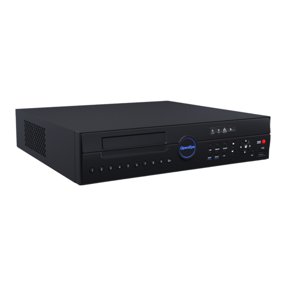
- Page 1 960H Recorder User Manual E-Series Max OE-EMAX8 OE-EMAX16 www.openeye.net...
- Page 3 The information in this publication is provided “as is” without warranty of any kind. The entire risk arising out of the use of this information remains with recipient. In no event shall OPENEYE be liable for any direct, consequential, incidental, special, punitive, or other damages whatsoever (including without...
-
Page 4: Important Safeguards
Object and Liquid Entry Points – Never insert foreign objects into the recorder, other than the media types approved by OpenEye, as they may touch dangerous voltage points or short-out parts that could result in a fire or electrical shock. Never spill liquid of any kind on the product. -
Page 5: Notes On Handling
When the unit exhibits a distinct change in performance - this indicates a need for service. 18. Servicing – Do not attempt to service this product unless instructed to by an OpenEye engineer. Opening or removing covers may expose the user to dangerous voltage or other hazards. - Page 6 NOTES ON MAINTENANCE This recorder is designed to last for long periods of time. To keep the recorder always operational we recommend regular inspection maintenance (cleaning parts or replacement). For details contact the nearest dealer. NOTES ON MOISTURE CONDENSATION Moisture condensation could damage the recorder. Read the following information carefully. Moisture condensation might occur under the following circumstances: ...
-
Page 7: Explanation Of Graphical Symbols
EXPLANATION OF GRAPHICAL SYMBOLS The lightning flash with arrowhead symbol, within an equilateral triangle, is intended to alert the user to the presence of un-insulated "dangerous voltage" within the product enclosure that may be of sufficient magnitude to constitute a risk of electric shock to persons. FCC STATEMENT This equipment has been tested and found to comply with the limits for a Class A digital device, pursuant to Part 15 of the FCC Rules. -
Page 8: Standard Warranty
OpenEye will warrant all otherwise out of warranty replacement parts and repairs for 90 days from the date of OpenEye shipment. The above warranty is the sole warranty made by OpenEye and is in lieu of all other warranties by OpenEye express and implied, including without limitation the warranties of merchantability and fitness for a particular purpose. -
Page 9: Table Of Contents
Introduction ............................13 Product Description ......................13 Features .......................... 14 USB Flash Drive Approved List ..................14 PTZ Compatibility List ..................... 15 Quick Start Instructions ....................16 Logging In for the First Time ................... 16 Installation ............................17 Front Panel Controls ....................... 17 Rear Panel Connectors.................... - Page 10 Camera ........................... 34 Camera Setup ......................34 Color Setup (Adjust) ..................35 PTZ Setup ....................... 35 Spot / Sequence Setup .................... 36 Monitor Setup ......................37 Record ..........................38 Recording Setup ...................... 38 Frame ....................... 38 Schedule ......................39 Holiday Setup ....................41 Audio ........................
- Page 11 Quick Search ......................61 Graphic Search ......................61 Quick Backup in Search Mode ................62 Express Search ....................... 62 Event Search ......................62 Jump to First Saved Data ..................62 Jump to Last Saved Data ..................62 Daylight Saving Search ................... 63 Search Popup Menu ....................
- Page 12 Notes...
-
Page 13: Introduction
E-Series recorders use an embedded Linux operating system, which provides stability and protection from viruses. OpenEye E-Series recorders are ready for fast and seamless integration within your existing IT infrastructure. These recorders are designed to offer unparalleled stability, security, and ease of use in each model. -
Page 14: Features
The E-Series Max includes the following features: DVD drive for optical media backup (CD or DVD) 8/16 composite video input connectors 16 looping video outputs (16ch model only) Compatible with color (NTSC or PAL) and B&W video sources ... -
Page 15: Ptz Compatibility List
OpenEye E-Series recorders support a wide selection of PTZ camera protocols: OpenEye 500 ORX-1000 OpenEye 510 Pelco-D OpenEye – Pelco D Pelco-P American Dynamics PTC-400C DynaColor RS-485 DIRECT D-Max SCC-641 ERNITech SCC-645A FastraxII SDM-100 Ganz-PT SJ-3728R1 Honeywell MAXPRO SK-P Honeywell VCL... -
Page 16: Quick Start Instructions
Turn on the recorder. See the Turning on the Recorder section of this manual for more details. Log in. The default password is 1234. Complete System Setup to set up the date, time and system ID. See the System section for more details. -
Page 17: Installation
LED Lights Power HDD Instant Backup Network DVD Drive Enter USB Port 32769AB... -
Page 18: Rear Panel Connectors
The rear panel of the recorder contains virtually all of the connectors you will be using. The diagram below shows the location and description of each connector. 16 Channel Video inputs TV Out (BNC) output Looping outputs PTZ / Sensor Input / Audio input Relay Output Power... -
Page 19: Channel
8 Channel TV out (BNC) output PTZ / Sensor input / Video inputs Audio input Relay output Power Audio output NTSC/PAL switch Network port Spot Monitor outputs VGA output HDMI output 32769AB... -
Page 20: Remote Control
ID Select* Instant Backup PTZ Controls Log Off (Lock) Emergency Record Display Options *The ID Select button allows you to use one remote control for several recorders. -
Page 21: Connection Guide
Connecting the Monitor There are three available monitor outputs on E-Series Max recorders. HDMI output for HDMI monitor Composite Monitor output for CCTV monitor – BNC (TV OUT) Spot monitor output for CCTV monitor – BNC (Marked SPOT) ... -
Page 22: Connecting A Ptz Camera
Connecting a PTZ Camera The RS485 connector can be used to control Pan / Tilt / Zoom (PTZ) cameras. See the PTZ camera manufacturer’s manual for configuring the RS485 connection. Connect RX-/TX- and RX+/TX+ of the control system to the TX-/RX- and TX+/RX+ (respectively) of the recorder. -
Page 23: Turning On The Recorder
Connect camera cables. Connect a network cable and a monitor cable. Connect the power cable to the recorder and wait until the main screen is displayed on the connected monitor; this process will take approximately two minutes. See the Connection Guide section for more details. Using the Front Panel to Turn On/Off the Recorder To start the recorder: ... - Page 24 Notes:...
-
Page 25: Setup
Use the setup menus to configure all of the recorder settings, schedule recording, networking and shutdown. Connect a USB mouse to the recorder to navigate setup menus and recorder functions. See the Logging In for the First Time section if entering setup for the first time If you do not have a USB mouse, you can press the SETUP key on the front of the recorder to enter the setup menus and log in. -
Page 26: Quick Setup
The Quick Setup allows you to define global recording settings for an easy and custom recording schedule on the recorder. Global Resolution – 352x240 / 704240 / 704480. Record Mode – CONTINUOUS / MOTION / SENSOR / CONTINUOUS+MOTION / CONTINUOUS+SENSOR / MOTION+SENSOR Average Days to Record –... -
Page 27: System
System Setup To enter System Setup, click MENU on the hover menu, and then click SETUP. Click SYSTEM, and then click SYSTEM SETUP. Click SAVE to save your updates. Video Format - NTSC / PAL, Display only. Use the PAL/NTSC switch on the back of the recorder to change the setting. Language - ENGLISH / SPANISH / FRENCH [User Selectable]. -
Page 28: Upgrade Firmware
System Setup Continued Use DST – After completing the Time Zone setup, click the USE DST value (ON or OFF) to enable or disable Daylight Saving Time. NTP Type – Click NTP TYPE to enable or disable a Network Time Protocol. In the NTP Type window, enable NTP SERVER, and then type your desired NTP Server URL. -
Page 29: Disk Setup
Disk Setup Shows installed Hard Disk Drives and the status of other attached storage devices. To format a Hard Drive or USB device, select the appropriate device, click FORMAT, and then click YES. Refer to the list of Approved USB Flash Drives in the Introduction of this manual. To refresh the list of connected USB devices, click RESET. -
Page 30: Overwrite
Sets options for overwriting data when the Hard Disk Drive becomes full. Enable HDD OVERWRITE to allow the recorder to write over previously recorded data, starting with the oldest date, when the HDD is full. If set to DISABLE the recorder will not record any new data once the HDD becomes full. -
Page 31: Smart Check
S.M.A.R.T. = Self Monitoring Analysis & Reporting Technology. Enable SMART Check to detect signs of HDD failure. Set ENABLE S.M.A.R.T. to ENABLE or DISABLE. Set a CHECK INTERVAL between 1 and 24 hours. Define a TEMP THRESHOLD and select Celsius or Fahrenheit. The recommended upper optimum operating temperature for the HDD is between 104°... -
Page 32: User Setup
User Setup Use the User Setup to Add or Delete users. -
Page 33: Adding / Changing A User
To add a new user: Click MENU on the hover menu and click SETUP. Click SYSTEM, and then click USER SETUP. Click ADD/CHANGE. Type a USER name. Type a PASSWORD and CONFIRM for the new user. Select the FUNCTION and SETUP access options for the user. Select which cameras will be visible to the user in LIVE and PLAYBACK modes. -
Page 34: Configuration
Configuration Import and Export current settings. See details in the Save Settings section. Shutdown Use Shutdown to safely shutdown the system. On the hover menu, click MENU, and then click SETUP. Click SYSTEM, and then click SHUTDOWN. Click OK. Turn the power off when shutdown is complete by unplugging the power adapter cord on the back of the recorder. -
Page 35: Color Setup (Adjust)
CAMERA – 1 ~ 16 [camera to apply color settings to] BRIGHTNESS – 0 ~ 20 CONTRAST – 0 ~ 20 COLOR – 0 ~ 20 DEFAULT – Apply default system color settings APPLY ALL – Apply current color settings to all cameras PTZ Setup CH –... -
Page 36: Spot / Sequence Setup
Spot / Sequence Setup Spot/Sequence Setup allows you to set the parameters for the SPOT OUT on the recorder and the local live view sequencing. SPOT – Configure the SPOT OUT connection. INTERVAL – Set the sequence interval time (1 ~ 100 seconds). POPUP –... -
Page 37: Monitor Setup
Monitor Setup TRANSPARENCY SETUP – Set the transparency of the setup windows (0 ~ 20). VGA RESOLUTION – Set monitor resolution. FIT-IN VGA – Adjusts the display to display properly on a VGA monitor. When FIT-IN VGA is not selected, the display is adjusted to display on a monitor connected to the TV Out BNC output. -
Page 38: Record
Recording Setup ON/OFF – Enable or disable recording on individual camera channels. SIZE – Choose the recording resolutions (352240 / 704240 / 704480 / 960x480). IPS – Choose the recording rate (1~30 Images Per Second). QUALITY – Choose the image quality (LOW / NORMAL / HIGH / HIGHEST). INTENSIVE –... -
Page 39: Schedule
Set the recording schedule for each camera. On the hover menu, click MENU, and then click SETUP. Click RECORD, and then click SCHEDULE. Select a camera to create a recording schedule, or select ALL. Select your desired RECORD MODE. Click hour block or the day of the week to set the entire day. NO RECORDING No recording. - Page 40 SENSOR Sensor-activated recording. Orange In sensor mode, the unit will record when a sensor is triggered - during DURATION time as set in RECORD > MOTION /EVENT CONFGURATION > ACTION. CONT+MOT Continuous and motion detection recording The unit records in CONTINUOUS mode but switches to Sky Blue MOTION when motion is detected in the motion area.
-
Page 41: Holiday Setup
Add a recording schedule for a specific date in HOLIDAY SETUP. You can add up to 32 individual holiday recording schedules. To add a new HOLIDAY schdule: On the hover menu, click MENU, and then click SETUP. Click RECORD, and then click RECORD SETUP. Click SCHEDULE. -
Page 42: Emergency Recording
Configure the recording settings for Emergency Recording and Instant Backup to use when they are activated. Emergency Record: IPS – Set the recording rate per camera (in Images Per Second). QUALITY – Set the picture quality (affects file size). SIZE – Set the resolution of the video image. Instant Backup: DEFAULT DURATION –... -
Page 43: Motion/Event Setup
Motion/Event Setup Motion / Event Setup has four sections; Input, Sensor, Action, and Alarm Monitor. When an event occurs (Input), the unit records the image according to its settings (Camera Setup) and triggers an alarm (Action). CH – Channels 1-8 will appear by default. To view channels 9-16, click CH. MOTION –... -
Page 44: Setting Up Motion Detection Recording
To record data only when motion is detected: On the hover menu, click MENU, and then click SETUP. Click RECORD, and then click MOTION/EVENT SETUP. Set MOTION to ON. Set the motion SENSITIVITY level. [1~10]. To set a global motion area (each channel can also be configured individually), click AREA. -
Page 45: Sensor
Sensor Setup Set the Sensor TYPE to N/O (Normally Open) or N/C (Normally Closed). Repeat for all sensors. Click SAVE. Alarm Setup Enable or disable the SIGNAL (ON / OFF). Set each alarm TYPE (NO / NC). Repeat for all relays. Click SAVE. -
Page 46: Action
CH – Channels 1-8 will appear by default. To view channels 9-16, click CH. Alarm – Associate an alarm relay with a camera channel (OFF / 1). Delay – Set the delay time for relay to activate (0~100 seconds). Duration – Set the duration of the alarm relay (0~100 seconds). Preset –... -
Page 47: Alarm Monitor
Send event information to a remote client using the Alarm Monitor software. Set SEND TO ALARM MONITOR to ON. Select the types of events to send to the Emergency Agent (MOTION, SENSOR, MOTION + SENSOR). Type the IP ADDRESS of the remote client. Type the PORT number. -
Page 48: Network
Network Setup Configure network settings. Network HOST NAME – Host name for the recorder on the network. NETWORK TYPE – Select STATIC IP to manually define a static IP address. Select DHCP for a DHCP server to assign an IP address automatically. Contact your network administrator for more information. -
Page 49: Serial Setup
Network Setup continued DDNS - Dynamic Domain Name Service (DDNS) is a service that allows a connection to an IP address using a hostname (URL) address instead of a numeric IP address. Most Internet Service Providers use Dynamic IP Addressing that frequently changes the public IP address of your internet connection;... -
Page 50: E-Mail Setup
E-mail Setup The recorder can send an e-mail notification to up to six defined e-mail addresses when an event happens. E-MAIL SERVER – Configure the recorder to use selected e-mail server (DVR / SMTP). OPTION – Define the type of event that will trigger an e-mail notification. MOTION –... -
Page 51: Reportstar
ReportStar To enable ReportStar on your recorder during the initial configuration: Click ENABLE REPORTSTAR NOW. To enable ReportStar at any time after the initial configuration, go to NETWORK > REPORTSTAR SETUP and then set ENABLE REPORTSTAR to ON. Log in using the admin user account. (default username: admin, password: 1234) Set the CUSTOM DAY/NIGHT TIME. -
Page 52: Information
System Log View Displays system log information. System Log View displays the recent activity of all users on the recorder. You can export and save the System Log to review user activity. Version View Displays system information and software version information for the recorder. -
Page 53: Status View
Status View Displays status screens for: Disk Record Audio 32769AB... - Page 54 Status View continued Sensor Network Event...
- Page 55 Notes: 32769AB...
-
Page 56: Operation
The LOG-IN window will display on the monitor until a user logs in with the correct ID and password. To prevent unauthorized changes to the system settings, the administrator should change the default administrator password and create a User account. Default Administrator Log In The default administrator account login is: USER: admin... -
Page 57: Icons
Icons In Live mode, icons or messages on the screen indicate the system mode or status. Right-upper corner on each CH. Right-bottom corner on full screen. Continuous Recording No HDD, Smart Alarm & HDD Failure Motion Detection Using Emergency Recording Recording Sensor Activated Using PTZ... -
Page 58: Mouse-Over Menu
Mouse-Over Menu Move the mouse to the bottom of the monitor in live mode. The hover menu will appear. Sequence – Click to start camera sequence. Emergency Recording – Click to start instant recording. In instant recording mode, the system records all channels at the recording rate configured on the Emergency Recording screen. -
Page 59: Popup Menu
Popup Menu Right-click the live screen to open the Popup Menu. HIDE LIVE VIEW – Hide the selected camera from Live view. RECORD CHANGE – Change the recording settings for that channel including PPS, quality, resolution, and event response. PAGE SEQUENCE – The SEQ icon appears on the bottom right of the screen and displayed channels will be sequentially changed. -
Page 60: Ptz
To enter PTZ mode: Right-click the Live screen and select PTZ on the pop-up menu. Click the PTZ icon on the hover menu. Drag the mouse up/down or left/right to move pan/tilt position of the camera. As you move the mouse away from the center of the screen, the camera movement speed increases. -
Page 61: Search
Searching Recorded Data Search recorded video on the recorder to find a specific time or event. On the hover menu, click MENU, and then click SEARCH. Select your TARGET media (HDD / USB / CD/DVD). Select your desired search method. Quick Search ... -
Page 62: Quick Backup In Search Mode
Quick Backup in Search Mode You can easily archive video while watching a video playback. Note: The Quick Backup is only available using the BACKUP button, provided on the 16 CH E-Series Slim recorder. 4 and 8 channel models do not provide this function. In the search mode: Press the BACKUP on the front panel to set the Start time. -
Page 63: Daylight Saving Search
Daylight Saving Search Daylight Saving Search is used to find recorded data after switching the time at the end of Daylight Saving Period. The System will record data with the same time stamp for two hours when they are repeated. If any overlapped time data exists the system will display the times on this page. -
Page 64: Backup (Export)
Manual Export Back up recorded data on a CD/DVD or connected USB device. Using this export method, video data is saved in a proprietary format and must be viewed using the Export Viewer software. To configure a data backup: Click MENU on the hover menu, and then click BACKUP. Connect a USB device or insert a CD/DVD. -
Page 65: Using The Backup Player
Play recorded video on a PC using Backup Player, the proprietary media player included with every backup file. Controlling Backup Player Next Frame Previous Frame Forward Play Back Play Pause 32769AB... -
Page 66: Setup And Save Functions
Setup and Save Functions These function buttons allow you to configure the Backup Player and save a JPEG image or AVI video. OPEN – Allows you to choose which data to open. When selecting data that is saved to your local hard drive, the video must be in a directory named DATA. Navigate to the folder above the DATA directory and click OK to see the available playback options. -
Page 67: Screen Division Buttons
Obtain the latest software release and save the file to a CD/DVD or USB device. Please check the product web site at www.openeye.net or contact Technical Support for the latest software. See the back cover of this manual for contact information. -
Page 68: Save Settings
Use the System Setup menu to export and import saved or factory default system settings. Save Settings On the hover menu, click MENU, and then click SETUP. Click SYSTEM, and then click CONFIGURATION. Select an empty PROFILE and define a name for the settings configuration. To save settings to a USB device, click EXPORT. -
Page 69: Remote Software
RADIUS is Video Management Software from OpenEye that allows you to access your recorder from any PC or laptop with a network connection. Use RADIUS to monitor live video, search recorded video, control PTZ cameras, export video, and even search live video as it happens. -
Page 70: Web Viewer Overview
Control Outputs Status of Alarm Sensors Camera Display Buttons Search Open the Search screen. PAN/TILT Open the PTZ controller. Export Image Save JPG file of selected image. Print Print selected image on connected printer. Connect Connect to an OpenEye recorder. -
Page 71: Connecting To A Recorder Using Web Viewer
Connecting to a Recorder Using Web Viewer Open Microsoft Internet Explorer. Enter the IP address of the recorder into the Address bar. When attempting this for the first time you will be asked to accept an Active X installation. Click Yes. If you receive a message saying Internet Explorer security settings do not allow you to download Active X components then you will need to adjust the browser security settings. -
Page 72: Performing A Basic Search
Click the Calendar icon to open the calendar and select a date. Select a time using the hour and minute control bars. Select one or more cameras. Click Play. (Video can be played forwards, backwards, or frame-by-frame.) The Status Search option displays a timeline in graph format. Scroll through multiple cameras and easily locate hours with recorded video. -
Page 73: Print
The message “NO DEFAULT PRINTERS INSTALLED” will display if no printer is installed. Using the OpenEye Web Viewer, you can export single images in the Image file formats and save video clips in an .AVI format. Both .JPG and .AVI file formats are the most commonly used graphical formats today. -
Page 74: Digital Verifier Overview
This program can be installed on any Windows XP, Windows Vista or Windows 7 computer. Using the Digital Verifier Open the Digital Verification program by selecting Start > Programs > OpenEye > Digital Verifier > Digital Signature Verifier. Click the Browse button to load the JPG image. -
Page 75: Appendix
LED Status Indicators Power Illuminates when power is supplied to the DVR. Flashes when the hard drive is being accessed. Network Illuminates when the DVR is connected to a network. Enter / Exit Buttons Enter Input data, make selections, and open pop-up menus. Exit Return to the previous mode or menu, without saving. -
Page 76: Function Buttons
Function Buttons Instant Backup Back up the most recent video instantly. Search Open the search menu. In the live view, press to enter PTZ mode. Backup In live mode, press to open the backup menu. For Quick Backup in the search mode: ... -
Page 77: Directional And Playback Control Buttons
Directional and Playback Control Buttons Adjust zoom, focus, and iris on a PTZ channel. Search Start reverse playback of recordings. Press successively to change the fast reverse speed. Adjust zoom, focus, and iris on a PTZ channel. Search Start playback of recordings. Press successively to change the fast forward speed. -
Page 78: Recorder Specifications
Motion Detection Adjustable sensitivity, Custom grid Remote Operation Live View, Setup, PTZ, Firmware update (Remote and RADIUS only) Remote Software OpenEye Remote, RADIUS, Web Viewer (Active X) PTZ Control RS-485 Schedules for Continuous, Motion, Sensor, Pre- and Post-Alarm Recording Mode... - Page 79 © 2014 OpenEye All rights reserved. No part of this publication may be reproduced by any means without written permission from OpenEye. The information in this publication is believed to be accurate in all respects. However, OpenEye cannot assume responsibility for any consequences resulting from the use thereof.
Need help?
Do you have a question about the 960H and is the answer not in the manual?
Questions and answers