Table of Contents
Advertisement
Advertisement
Chapters
Table of Contents

Related Manuals for Zte ZXR10 T8000


Summary of Contents for Zte ZXR10 T8000
- Page 1 ZXR10 T8000 Carrier-Class Router Hardware Installation Guide (Cluster) Version: 1.00.10 ZTE CORPORATION NO. 55, Hi-tech Road South, ShenZhen, P.R.China Postcode: 518057 Tel: +86-755-26771900 Fax: +86-755-26770801 URL: http://ensupport.zte.com.cn E-mail: support@zte.com.cn...
- Page 2 ZTE CORPORATION is prohibited. Additionally, the contents of this document are protected by contractual confidentiality obligations. All company, brand and product names are trade or service marks, or registered trade or service marks, of ZTE CORPORATION or of their respective owners.
-
Page 3: Table Of Contents
Contents About This Manual ..................I Chapter 1 Introduction to Cluster ............. 1-1 1.1 Overview of Cluster .................... 1-1 1.2 Hardware Composition of Cluster ................ 1-2 1.3 Physical Parameters of Cluster ................1-5 1.4 Cluster Installation Flow..................1-8 Chapter 2 Installation of Cluster in 1+4 Mode ......... 2-1 2.1 Installation Preparations .................. - Page 4 A.5 ESD Antistatic Safety ..................A-4 A.6 Electromagnetic Environment ................A-5 A.7 Lightning Protection Ground ................A-6 Appendix B Label Specification............... B-1 B.1 Label Specification Introduction ................B-1 B.1.1 Label Making Requirements ..............B-1 B.1.2 Label Paste Precautions................B-1 B.1.3 Equipment Labels ..................B-2 B.2 Knife-shaped Label ....................
-
Page 5: About This Manual
Metropolitan Area Networks (MANs), ZXR10 T8000 is committed to constructing a flat network and emphasizing the long-term evolution of a unified bearer network. Thus, ZXR10 T8000 is an ideal choice for network operators to build their competitive networks. - Page 6 Describes how to make and stick labels, and how to use a knife-shaped Specification label and rectangular label. Conventions ZTE documents employ the following typographical conventions. Typeface Meaning Italics Variables in commands. It may also refers to other related manuals and documents.
-
Page 7: Chapter 1 Introduction To Cluster
As data can be forwarded between shelves through a switching matrix, a router cluster provides higher efficiency than single-machine routers. A router cluster also has these advantages: easier to adjust routes and traffic, more powerful manageability, higher expandability, availability and maintenance efficiency. SJ-20110901170352-005|2011-10-15 (R2.0) ZTE Proprietary and Confidential... -
Page 8: Hardware Composition Of Cluster
CLOS switching networks, the same types of boards, and the same models of interconnection optical cables. However, cluster 1+4 and cluster 2+8 of ZXR10 T8000 are still different in terms of: Maximum switching capacity: The switching capacity of a ZXR10 T8000 single-machine router is 1.92Tbps, so the switching capacity of a cluster 1+4 system... -
Page 9: Figure 1-1 Zxr10 T8000 Central Switching Shelf And Line Card Shelf
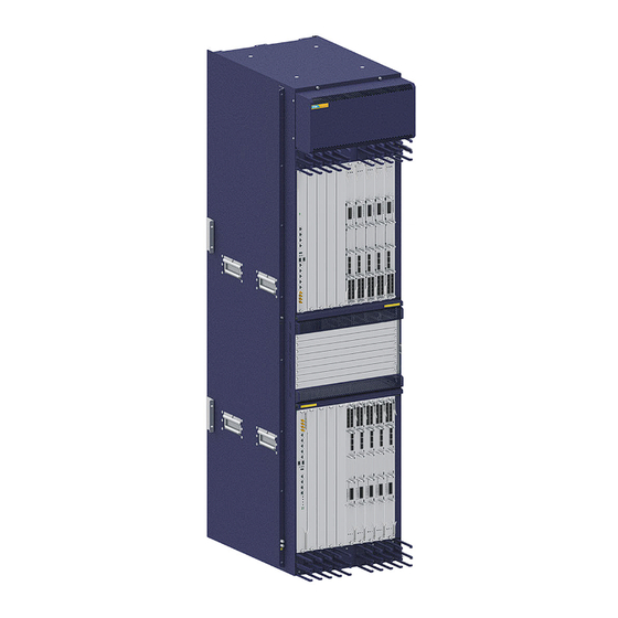
Chapter 1 Introduction to Cluster Figure 1-1 ZXR10 T8000 Central Switching Shelf and Line Card Shelf The slot allocation within a central switching shelf and a line card shelf is as shown in Figure 1-2. SJ-20110901170352-005|2011-10-15 (R2.0) ZTE Proprietary and Confidential... -
Page 10: Figure 1-2 Slot Allocation Within A Central Switching Shelf And Line Card Shelf
Cluster 1+4 ZXR10 T8000Cluster 1+4 is composed of one central switching shelf and up to 4 line card shelves. The overall cascade connections of ZXR10 T8000 cluster 1+4 are as shown in Figure 1-3. Figure 1-3 Overall Cascade Connections of ZXR10 T8000 Cluster 1+4 SJ-20110901170352-005|2011-10-15 (R2.0) -
Page 11: Physical Parameters Of Cluster
Figure 1-4 Overall Cascade Connections of ZXR10 T8000 Cluster 2+8 1.3 Physical Parameters of Cluster Physical Parameters of a Line Card Shelf For the parameters of a line card shelf of the ZXR10 T8000 cluster system, see Table 1-1. Table 1-1 Physical Parameters of a Line Card Shelf of the ZXR10 T8000 Cluster System... - Page 12 ZXR10 T8000 Hardware Installation Guide (Cluster) Physical Parameter ZXR10 T8000 Per slot 100Mpps Packet forwarding capacity Per machine 1600Mpps Backup mode Rated power per machine 6000W Rated voltage -48V DC power supply Maximum voltage range -60V - -40V Rated input current...
-
Page 13: Table 1-2 Physical Parameters Of A Central Switching Shelf Of The Zxr10 T8000 Cluster System
0.5°C for every 100-meter increase in altitude. The maximum supported altitude is 5000m. Physical Parameters of a Central Switching Shelf For the parameters of a central switching shelf of the ZXR10 T8000 cluster system, see Table 1-2. Table 1-2 Physical Parameters of a Central Switching Shelf of the ZXR10 T8000 Cluster... -
Page 14: Cluster Installation Flow
0.5 ℃ for every 100-meter increase in altitude. The maximum supported altitude is 5000m. 1.4 Cluster Installation Flow This topic describes how to install ZXR10 T8000 cluster 1+4 and cluster 2+8. The installation flow of the two clusters is basically the same, as shown in Figure 1-5. -
Page 15: Figure 1-5 Zxr10 T8000 Cluster Installation Flow
Chapter 1 Introduction to Cluster Figure 1-5 ZXR10 T8000 Cluster Installation Flow SJ-20110901170352-005|2011-10-15 (R2.0) ZTE Proprietary and Confidential... - Page 16 ZXR10 T8000 Hardware Installation Guide (Cluster) This page intentionally left blank. 1-10 SJ-20110901170352-005|2011-10-15 (R2.0) ZTE Proprietary and Confidential...
-
Page 17: Installation Preparations
2.2.1 Installing Cascade Data Cables Data Cable Cascading Method The cascade data cables in the ZXR10 T8000 cluster system are optical cables. It is required that the cascade interfaces of each cascade switching network board (MSPU) on a line card shelf (LCC) be connected to the cascade interfaces of a central switching network board (CSFU) on the central switching shelf, so as to form a three-level CLOS switching architecture. -
Page 18: Figure 2-1 Zxr10 T8000 Data Plane Cascade Connections Of Cluster 1+4
ZXR10 T8000 Hardware Installation Guide (Cluster) The data plane cascade connections of the ZXR10 T8000 cluster 1+4 system are as shown Figure 2-1. The interfaces on an LCC are connected to the interfaces of the same color and number on the CFC. -
Page 19: Figure 2-2 Data Plane Cascade Fibers
3. Stick labels on both sides of the fiber to describe the information about the fiber. 4. Use cable straps to organize and bind the fibers in compliance with related specifications. The data plane cascade fibers of the ZXR10 T8000 cluster system are as shown in Figure 2-2. -
Page 20: Installing Cascade Control Cables
Figure 2-3 Some Rows of Fibers Connected in the Cluster Installation 2.2.2 Installing Cascade Control Cables The cascade control cables in the ZXR10 T8000 cluster system are optical fibers. It is required that the cascade interfaces of each main control board (MPU) on a line card shelf... -
Page 21: Installing Cascade Clock Cables
Figure 2-4 ZXR10 T8000 Control Plane Cascade Connections of Cluster 1+4 2.2.3 Installing Cascade Clock Cables The connections of the cascade clock cables among multiple devices in the ZXR10 T8000 cluster 1+4 system are as shown in Figure 2-5. -
Page 22: Figure 2-5 Cascade Clock Cables Among Multiple Devices
ZXR10 T8000 Hardware Installation Guide (Cluster) Figure 2-5 Cascade Clock Cables Among Multiple Devices SJ-20110901170352-005|2011-10-15 (R2.0) ZTE Proprietary and Confidential... -
Page 23: Installation Preparations
3.2 Installation of Cascade Connection Cables 3.2.1 Installing Cascade Data Cables The cascade data cables in the ZXR10 T8000 cluster are optical cables. It is required that the cascade interfaces of each cascade switching network board (MSPU) on a line... -
Page 24: Figure 3-1 Zxr10 T8000 Data Plane Cascade Connections Of Cluster 2+8
ZXR10 T8000 Hardware Installation Guide (Cluster) Figure 3-1 ZXR10 T8000 Data Plane Cascade Connections of Cluster 2+8 For how to install cascade fibers, refer to section 2.2.1 "Installing Cascade Data Cables". SJ-20110901170352-005|2011-10-15 (R2.0) ZTE Proprietary and Confidential... -
Page 25: Installing Cascade Control Cables
Chapter 3 Installation of Cluster in 2+8 Mode 3.2.2 Installing Cascade Control Cables The cascade control cables in the ZXR10 T8000 cluster system are optical fibers. It is required that the cascade interfaces of each main control board (MPU) on a line card shelf... -
Page 26: Installing Cascade Clock Cables
Figure 3-2 ZXR10 T8000 Control Plane Cascade Connections of Cluster 2+8 3.2.3 Installing Cascade Clock Cables The cascade clock cables in the ZXR10 T8000 cluster 2+8 system are normal cables. It is required that the clock interfaces of all the main control board (MPUs) on a line card SJ-20110901170352-005|2011-10-15 (R2.0) - Page 27 If multiple clock references are available, refer to Figure 3-3 to connect the cascade clock cables. Figure 3-3 Clock Cable Cascading of ZXR10 T8000 Cluster 2+8 — Mode 1 If multiple clock references are not available, refer to Figure 3-4 to connect the cascade clock cables.
- Page 28 ZXR10 T8000 Hardware Installation Guide (Cluster) Figure 3-4 Clock Cable Cascading of ZXR10 T8000 Cluster 2+8 — Mode 2 SJ-20110901170352-005|2011-10-15 (R2.0) ZTE Proprietary and Confidential...
-
Page 29: Chapter 4 Installing Signal Cables
Install the other signal cables of the cluster system, such as configuration cables, network cables, and regular fibers. For details, refer to Chapter 5 "Routing Signaling Cables" in the ZXR10 T8000 Carrier-Class Router Hardware Installation Guide (Single Machine). SJ-20110901170352-005|2011-10-15 (R2.0) - Page 30 ZXR10 T8000 Hardware Installation Guide (Cluster) This page intentionally left blank. SJ-20110901170352-005|2011-10-15 (R2.0) ZTE Proprietary and Confidential...
-
Page 31: Chapter 5 Equipment Power-On And Power-Off
Whether the expansion bolt used to fix the cabinet or base (bracket) to On-site check the ground is securely installed; Whether there exist flat washer and spring washer; Whether the spring washer is on the flat washer SJ-20110901170352-005|2011-10-15 (R2.0) ZTE Proprietary and Confidential... - Page 32 ZXR10 T8000 Hardware Installation Guide (Cluster) Check Items Checking Method Whether the expansion bolt fits the installation holes of the base Set the multimeter to measure bracket and support leg; the resistance value of the Whether the bracket and the ground are insulated;...
-
Page 33: Power Cable And Grounding Check
On-site check cut off. No prickle should remain All signal cables should pass the circuit continuity check before cable On-site check routing Signal cables should not be deployed on the cabinet cooling holes On-site check SJ-20110901170352-005|2011-10-15 (R2.0) ZTE Proprietary and Confidential... -
Page 34: Equipment Power-On
ZXR10 T8000 Hardware Installation Guide (Cluster) Check Items Checking Method Cables at bends should not be pulled too tight On-site check Whether the routed cables are straight and even. No cable crossover On-site check exists in the cabinet. Cables outside the cabinet are banded Labels at both ends of the signal cable should be clear. - Page 35 When engineers dismantle power supply module and cables after equipment power-off, it is recommended to shut off the circuit breaker of the equipment power distribution box first; then shut off the circuit breaker of the power supply module. SJ-20110901170352-005|2011-10-15 (R2.0) ZTE Proprietary and Confidential...
- Page 36 ZXR10 T8000 Hardware Installation Guide (Cluster) This page intentionally left blank. SJ-20110901170352-005|2011-10-15 (R2.0) ZTE Proprietary and Confidential...
-
Page 37: Appendix A Equipment Operation Environment Requirements
Ÿ Anti-poisonous Gas ....................A-3 Ÿ ESD Antistatic Safety....................A-4 Ÿ Electromagnetic Environment ................. A-5 Ÿ Lightning Protection Ground ................... A-6 A.1 Equipment Room Building The ZXR10 T8000 equipment room building requirements are described in Table A-1. Table A-1 Equipment Room Building Requirements Item... -
Page 38: Temperature, Humidity And Altitude
Avoid the breeding of microorganisms such as epiphyte and mildew. No rodent animals (for example, rats) should exist. A.2 Temperature, Humidity and Altitude The ZXR10 T8000 requirements for temperature, humidity, and altitude are described in Table A-2. Table A-2 Temperature, Humidity and Altitude Requirements... -
Page 39: Anti-Poisonous Gas
The various types of dusts in the air that settles on equipment circuit cause electrostatic incorporation, leading to poor contact between metallic joints or short circuit. This might result in equipment fault and affects equipment life. The ZXR10 T8000 requirements for equipment room cleanliness are shown in Table A-3. -
Page 40: Esd Antistatic Safety
ZXR10 T8000 Hardware Installation Guide (Cluster) Chemical Substance Unit Concentration Requirements (Ozone) mg/m Average permitted value: 0.05; Maximum permitted value: 0.1 Nox (Nitrogen Oxide) mg/m Average permitted value: 0.5; Maximum permitted value: 1.0 Take the following measures to meet the requirements described above. -
Page 41: Electromagnetic Environment
For the whole equipment, EMS meets the European Telecommunication Standard Institute (ETSI) 300386 requirements. For equipment ports, EMS meets the GR1089 TYPE2 port requirements. The Electromagnetic Interference (EMI) requirements for electromagnetic emission are presented below. SJ-20110901170352-005|2011-10-15 (R2.0) ZTE Proprietary and Confidential... -
Page 42: Lightning Protection Ground
ZXR10 T8000 Hardware Installation Guide (Cluster) The whole equipment Radiated Emission (RE) meets the CISPR22 CLASS A requirements. The whole equipment power interface CS meets the CISPR22 CLASS A requirements. For the whole equipment communication port CS, CISPR22 CLASS A requirements should be met for non-shielded cables, while Class B requirements should be met for shielded cables. -
Page 43: Appendix B Label Specification
Detailed label making requirements are described below. Label content should be printed rather than written by hand. For ZTE labels, use the printing template that corresponds to the label type. Format requirements are as follows. Font size for site name: 13.75 pt; font size for others: 9 pt. -
Page 44: Equipment Labels
ID, the corresponding local equipment ID, subrack ID, optical line board slot ID, port ID and transmit/receive relationship. B.2 Knife-shaped Label B.2.1 Label Shape and Paste Position After cable installation, mark each cable end with a cable label. The label uses ZTE dedicated label, as shown in Figure B-1(a). -
Page 45: Electrical Cable Label
The other end: “To: “Type”” used to indicate cable type and opposite-end port ID. The “Type” field represents cable data type, such as “75 Ω”, “120 Ω”, “RS232”. Recommended ID rules of the electrical cable interfaces on the ZTE communication equipment side are shown in Table B-1. -
Page 46: Table B-2 Ddf Cable Interface Id Format
ZXR10 T8000 Hardware Installation Guide (Cluster) Meaning Specification Example B: Subrack ID. (number) The subracks from top to bottom are numbered in ascending order. When the independently installed equipment or rack contains only one subrack, the subrack ID should be 1 C: Slot ID. -
Page 47: Power Cable Label
One end: “POWER (Fr:)” used to indicate power port ID at local end. The other end: “POWER (To:)” used to indicate power port ID at opposite end. ID rules of the power ports on the ZTE communication equipment side are shown in Table B-3. -
Page 48: Fiber Cable
One end: “FR:” used to indicate optical interface ID at local end. The other end: “To:” used to indicate optical interface ID at opposite end. ID format requirements of the fiber pigtail interfaces on the ZTE communication equipment side are shown in Table B-5. -
Page 49: Table B-5 Fiber Pigtail Interface Id Forma
X: System name X: The same with the system name IP01 A: Equipment ID in contract ID A: IDs of ZTE equipment and cabinets in one site should be deployed uniformly and each ID should be unique. B: Subrack ID (number) The subracks from top to bottom are numbered in ascending order. -
Page 50: Ethernet Cable Engineering Label
ZXR10 T8000 Hardware Installation Guide (Cluster) Figure B-4 Knife-Shaped Fiber Pigtail Label Example B.2.5 Ethernet Cable Engineering Label The specification of the Ethernet cable engineering Label is similar to that of fiber label. Please refer to the previous topic. B.3 Rectangular Label B.3.1 Horizontal English Label for Panel or Plug... -
Page 51: Laser Print Wrapping Label (Type Ii
B.3.3 Label Pasted on Cable B.3.3.1 Power Cable Label The engineering mark for power cable uses the flag-shaped label made by ZTE. Label layout is shown in Figure B-7. -
Page 52: Figure B-8 Power Cable Label Paste Position
ZXR10 T8000 Hardware Installation Guide (Cluster) Figure B-8 Power Cable Label Paste Position The two areas on the flag-shaped power cable label are L and R, which are described below. L: Location of the near-end equipment, which is the location of the local equipment to which the power cable is connected. -
Page 53: Figure B-10 Fiber Cable Engineering Label Content
ZXR10 equipment side. B.3.3.3 Coaxial Cable Label The engineering label for coaxial cable is shown in Figure B-11. Figure B-11 Coaxial Cable Engineering Label Label content is described in Figure B-12. B-11 SJ-20110901170352-005|2011-10-15 (R2.0) ZTE Proprietary and Confidential... -
Page 54: Figure B-12 Coaxial Cable Engineering Label Content
ZXR10 T8000 Hardware Installation Guide (Cluster) Figure B-12 Coaxial Cable Engineering Label Content The two areas on the coaxial cable engineering label are L and R, which are described below. When the label is pasted on the coaxial cable on the ZXR10 equipment side, the content in Area R should be the DDF frame Row ID and Line ID, number of the DDF tier where the cable is located and cable serial number. -
Page 55: Cable Length Label
Ethernet interface board 10/100Base-T. B.4 Cable Length Label The user may mark cable length according to the on-site situation. It is recommended to use ZTE dedicated labels to mark cable length. The label is shown in Figure B-15. Figure B-15 Cable Length Label Dimension and Content Label content indicates cable length, for example, the “15 m”... - Page 56 ZXR10 T8000 Hardware Installation Guide (Cluster) This page intentionally left blank. B-14 SJ-20110901170352-005|2011-10-15 (R2.0) ZTE Proprietary and Confidential...
-
Page 57: Figures
Figure 3-2 ZXR10 T8000 Control Plane Cascade Connections of Cluster 2+8 ... 3-4 Figure 3-3 Clock Cable Cascading of ZXR10 T8000 Cluster 2+8 — Mode 1 ..... 3-5 Figure 3-4 Clock Cable Cascading of ZXR10 T8000 Cluster 2+8 — Mode 2 ..... 3-6 Figure B-1 Knife-Shaped Label Dimension and Paste Position .........B-3... - Page 58 Figures This page intentionally left blank.
-
Page 59: Tables
Tables Table 1-1 Physical Parameters of a Line Card Shelf of the ZXR10 T8000 Cluster System..................... 1-5 Table 1-2 Physical Parameters of a Central Switching Shelf of the ZXR10 T8000 Cluster System..................1-7 Table 5-1 Equipment Installation Check List .............. 5-1 Table 5-2 Power Cable and Equipment Grounding Check List ........ - Page 60 Tables This page intentionally left blank.
-
Page 61: Glossary
Glossary - Electromagnetic Interference - Electromagnetic Susceptibility ETSI - European Telecommunication Standard Institute - Main Distribution Frame...
Need help?
Do you have a question about the ZXR10 T8000 and is the answer not in the manual?
Questions and answers