Canon iPF6100 Service Manual
Canon ipf6000 series laser printers service manual
Hide thumbs
Also See for iPF6100:
- User manual (736 pages) ,
- Service manual (692 pages) ,
- Brochure & specs (8 pages)
Table of Contents
Advertisement
Quick Links
Advertisement
Table of Contents
Troubleshooting

Subscribe to Our Youtube Channel
Related Manuals for Canon iPF6100


Summary of Contents for Canon iPF6100
-
Page 1: Service Manual
Service Manual iPF6000 series Aug 13 2008... - Page 3 Canon will release technical information as the need arises. In the event of major changes in the contents of this manual over a long or short period, Canon will issue a new edition of this manual.
-
Page 4: Symbols Used
Introduction Symbols Used This documentation uses the following symbols to indicate special information: Symbol Description Indicates an item of a non-specific nature, possibly classified as Note, Caution, or Warning. Indicates an item requiring care to avoid electric shocks. Indicates an item requiring care to avoid combustion (fire). Indicates an item prohibiting disassembly to avoid electric shocks or problems. - Page 5 Introduction The following rules apply throughout this Service Manual: 1. Each chapter contains sections explaining the purpose of specific functions and the relationship between electrical and mechanical systems with refer- ence to the timing of operation. In the diagrams, represents the path of mechanical drive; where a signal name accompanies the symbol , the arrow indicates the direction of the electric signal.
-
Page 7: Table Of Contents
Contents Contents Chapter 1 PRODUCT DESCRIPTION 1.1 Product Overview ............................1- 1 1.1.1 Product Overview ..............................1- 1 1.1.2 Product Overview ..............................1- 2 1.1.3 Product Overview ..............................1- 3 1.2 Features ..............................1- 4 1.2.1 Features .................................. 1- 4 1.2.2 Features .................................. 1- 4 1.2.3 Features .................................. - Page 8 Contents 1.7.3 Precautions When Servicing Printer ........................1- 101 1.7.3.1 Notes on the Data Stored in the Printer ..........................1- 101 1.7.3.2 Confirming the Firmware Version ............................1- 101 1.7.3.3 Precautions against Static Electricity ........................... 1- 101 1.7.3.4 Precautions for Disassembly/Reassembly........................... 1- 101 1.7.3.5 Self-diagnostic Feature ................................
- Page 9 Contents 2.4.5 Maintenance Cartridge Relay PCB........................2- 60 2.4.5.1 Maintenance cartridge relay PCB components........................2- 60 2.4.6 Power Supply ................................ 2- 61 2.4.6.1 Power supply block diagram ..............................2- 61 2.5 Detection Functions with Sensors ......................2- 62 2.5.1 Sensors for covers..............................2- 62 2.5.2 Ink passage system...............................
- Page 10 Contents 4.5 Adjustment and Setup Items ........................4- 59 4.5.1 Adjustment Item List ..............................4- 59 4.5.2 Procedure after Replacing the Carriage Unit or Multi Sensor................4- 59 4.5.3 Procedure after Replacing the Head Management Sensor ...................4- 62 Chapter 5 MAINTENANCE 5.1 Periodic Replacement Parts ........................5- 1 5.1.1 Periodic Replacement Parts ............................5- 1 5.2 Consumable Parts ............................
- Page 11 Contents 6.1.3.29 03830101-2521/03830104-2520/03830102-2522/03830103-2523/03830112-2524/03830113-2525/03830106-2526/ 03830105-2528/03830115-2529/03830107-252A/03830109-252B/03830108-252C Ink tank is not installed.(This error occurs when the ink tank is replaced.) ................................6- 9 6.1.3.30 03830201-2541/03800204-2540/03830202-2542/03830203-2543/03830212-2544/03830213-2545/03830206-2546/ 03830205-2548/03830215-2549/03830207-254A/03830209-254B/03830208-254C Invalid ink tank ID........6- 9 6.1.3.31 03830301-2561/03830304-2560/03830302-2562/03830303-2563/03830312-2564/03830313-2565/03830306-2566/ 03830305-2568/03830305-2568/03830315-2569/03830307-256A/03830309-256B/03830308-256C Ink tank EEPROM error ... 6- 9 6.1.3.32 03841001-2819/03841201-2816/03841201-2817/03841101-2818/01841001-281B Maintenance cartridge error....6- 9 6.1.3.33 03861001-2405/03861001-2406 Borderless printing error ....................
- Page 12 Contents 8.4.2 Service Call Errors ..............................8- 25...
-
Page 13: Chapter 1 Product Description
Chapter 1 PRODUCT DESCRIPTION... - Page 15 Contents Contents 1.1 Product Overview ................................1-1 1.1.1 Product Overview ..................................1-1 1.1.2 Product Overview ..................................1-2 1.1.3 Product Overview ..................................1-3 1.2 Features ..................................1-4 1.2.1 Features ......................................1-4 1.2.2 Features ......................................1-4 1.2.3 Features ......................................1-4 1.2.4 Printhead ...................................... 1-5 1.2.5 Ink Tank .......................................
- Page 16 Contents 1.7.3 Precautions When Servicing Printer ............................1-101 1.7.3.1 Notes on the Data Stored in the Printer ..............................1-101 1.7.3.2 Confirming the Firmware Version................................1-101 1.7.3.3 Precautions against Static Electricity................................1-101 1.7.3.4 Precautions for Disassembly/Reassembly ..............................1-101 1.7.3.5 Self-diagnostic Feature ....................................1-101 1.7.3.6 Disposing of the Lithium Battery ................................
-
Page 17: Product Overview
1.1.1 Product Overview 0016-8093 iPF6100 This printer is capable of printing on A4- to A1-size cut sheets and its maximum print width is 24 inches. This printer is a desktop large-format printer twelve-colors (pigment-based colors) printer that can be used to print office documents as well as handy POP and posters. An auto roll feed unit is equipped for printing on roll media. -
Page 18: Product Overview
Chapter 1 1.1.2 Product Overview 0020-1808 iPF6200 This printer is capable of printing on A4- to A1-size cut sheets and its maximum print width is 24 inches. This printer is a desktop large-format printer twelve-colors (pigment-based colors) printer that can be used to print office documents as well as handy POP and posters. An auto roll feed unit is equipped for printing on roll media. -
Page 19: Product Overview
Chapter 1 1.1.3 Product Overview 0020-7368 iPF6000S This printer is capable of printing on A4- to A1-size cut sheets and its maximum print width is 24 inches. This printer is a desktop large-format printer eight-colors (pigment-based colors) printer that can be used to print office documents as well as handy POP and posters. An auto roll feed unit is equipped for printing on roll media. -
Page 20: Features
- Data scanned using CanoScan can be easily printed on large-size paper just like a dedicated copier. Just pressing the Start button allows you to blow up an original of up to A3 size in collaboration with Canon Image RUNNER. -
Page 21: Printhead
Chapter 1 1.2.4 Printhead 0012-6187 iPF6100 / iPF6200 / iPF6000S Printhead set on the carriage is a 6-color integral disposable type. On the printhead, two rows of 1,280 nozzles (total 2,560 nozzles) are arranged in a staggered pattern. . If print quality does not improve despite carrying out the specified cleaning, the printhead must be replaced with a new one. Generally, it is recommended that the printhead be replaced about 12 months after you have opened the package. -
Page 22: Ink Tank
Chapter 1 1.2.6 Ink Tank 0020-7255 iPF6000S The ink tank is disposable. There are eight pigment-based ink colors (matte black,black,photo cyan,cyan,photo magenta,magenta,yellow and gray). This printer features a mechanism by which only the correct color ink tank will fit in the given slot. When the message No Ink is displayed, replace the ink tank with a new one. -
Page 23: Cutter
Chapter 1 1.2.7 Cutter 0013-3524 iPF6100 / iPF6200 / iPF6000S A round-blade cuter comes with the cutter unit. F-1-10 1.2.8 Roll Feed Unit 0013-2512 iPF6100 / iPF6200 / iPF6000S Roll Feed Unit The roll feed unit is optionally available to use roll media with this printer. -
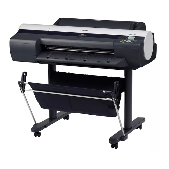
Page 24: Stand
1.2.9 Stand 0016-8107 iPF6100 / iPF6200 / iPF6000S Stand (Option) It is a stand that puts the printer. Equipped with casters so that the printer can be easily moved. The output stacker included with stand can use by the two ways of the regular position or extended position. - Page 25 Chapter 1 IEEE1394 (FireWire) expansion board (option) An interface board that provides an additional IEEE1394 (FireWire) port. F-1-18...
-
Page 26: Consumables
Chapter 1 1.2.12 Consumables 0016-8111 iPF6100 / iPF6200 Printhead The consumable print head is the same as that supplied with the printer. F-1-19 Ink Tanks The consumable ink tanks are available in twelve colors (matte black, black, photo cyan, cyan, photo magenta, magenta, yellow, red, blue, green, photo gray, and gray). -
Page 27: Consumables
Chapter 1 1.2.13 Consumables 0020-7258 iPF6000S Printhead The consumable print head is the same as that supplied with the printer. F-1-22 Ink Tanks The consumable ink tanks are available in eight colors (matte black, black, photo cyan, cyan, photo magenta, magenta, yellow and gray). They are the same as those supplied with the printer. -
Page 28: Product Specifications
Chapter 1 1.3 Product Specifications 1.3.1 Product Specifications 0016-8112 iPF6100 Type Bubble jet large-sized paper printer Feeding system Automatic feeding of one roll media/One cut sheet (manual feed from front)/One cut sheet (manual feed from top) Feeding capacity - Roll media... -
Page 29: Product Specifications
Chapter 1 Printable area (Roll media) Area excluding 3mm from the leading edge, 3 mm from the trailing edge, and 3 mm from the left and right edges. Borderless printing: 0 mm from the leading edge, trailing edge, and left and right edges. - Page 30 Chapter 1 Feeding capacity - Roll media One roll at the back/Outer diameter of roll: 150 mm or less/Inner diameter of paper tube: 2 or 3 inches - Cut sheet 1 sheet Delivery method Delivers the media with its printed side up in the forward direction. Sheet delivery capability Using the stand (option) basket: - Roll media...
-
Page 31: Product Specifications
Chapter 1 Printable area (Cut sheet) Area excluding 3 mm from the leading edge, 3 mm from the trailing edge (23 mm when supplied from manual feed from top or selected the fine art), and 3 mm from the left and right edges. Printing recommendation area Area excluding 20 mm from leading edge, 5 mm from the trailing edge (Roll media) - Page 32 Chapter 1 Type of media - Roll media Plain Paper, Economy Bond Paper, Universal Bond Paper, Plain Paper (High Quality), Plain Paper (High Grade), Recycled Coated Paper, Matte Coated Paper 90gsm, Coated Paper, Premium Coated Paper, Heavyweight Coated Paper, Extra Heavyweight Coated Paper, Premium Matte Paper, Glossy Photographic Paper 190gsm, Satin Photographic Paper 190gsm, Glossy Photographic Paper 240gsm, Satin Photographic Paper 240gsm, HW Glossy Photo Paper, HW Satin Photo Paper,...
-
Page 33: Detailed Specifications
During standby: 1 W or less Printer unit dimensions 1177 x 670 x 344 mm (WxDxH) With stand (option): 1177 x 870 x 991 mm Weight Approx. 51 kg 1.4 Detailed Specifications 1.4.1 Print Speed and Direction 0016-9138 iPF6100 / iPF6200 / iPF6000S 1-17... - Page 34 Chapter 1 T-1-4 Print Print Print- Used BK Media Type Print Priority Printing direction Resolution Quality Pass (dpi) Plain Paper/ Plain Paper Office Document Standard Bi-directional 1200x1200 Recycled Paper Line Document/ Draft Bi-directional 1200x1200 Text Standard Bi-directional 1200x1200 Image Draft Bi-directional 1200x1200 Standard...
- Page 35 Chapter 1 Print Print Print- Used BK Media Type Print Priority Printing direction Resolution Quality Pass (dpi) Coated Paper Coated Paper Standard Bi-directional 1200x1200 Image High Bi-directional 2400x1200 Highest Bi-directional 2400x1200 Heavyweight Coated Paper Standard Bi-directional 1200x1200 Image High Bi-directional 2400x1200 Highest Bi-directional...
- Page 36 Chapter 1 Print Print Print- Used BK Media Type Print Priority Printing direction Resolution Quality Pass (dpi) Photo Paper Glossy Photo Paper Standard Bi-directional 1200x1200 Image High Bi-directional 2400x1200 Highest Bi-directional 2400x1200 Semi-Glossy Photo Paper Standard Bi-directional 1200x1200 Image High Bi-directional 2400x1200 Highest...
- Page 37 Chapter 1 Print Print Print- Used BK Media Type Print Priority Printing direction Resolution Quality Pass (dpi) Art Paper Fine Art Photo Standard Bi-directional 1200x1200 Image High Bi-directional 2400x1200 Highest Bi-directional 2400x1200 Fine Art Heavyweight Photo Standard Bi-directional 1200x1200 Image High Bi-directional 2400x1200...
- Page 38 Chapter 1 Print Print Print- Used BK Media Type Print Priority Printing direction Resolution Quality Pass (dpi) Standard Bi-directional 1200x1200 Scrim Banner 370g Image High Bi-directional 2400x1200 Highest Bi-directional 2400x1200 Mat Film Paper Standard Bi-directional 1200x1200 Adhesive Matt Stretch Vinyl Image High Bi-directional...
-
Page 39: Interface Specifications
Chapter 1 1.4.2 Interface Specifications 0020-1816 iPF6200 / iPF6000S a. USB (standard) (1) Interface type USB 2.0 Hi-Speed (Full speed (12 Mbits/sec), High speed (480 Mbits/sec)) (2) Data transfer system Control transfer Bulk transfer (3) Signal level Compliant with the USB standard. (4) Interface cable Twisted-pair shielded cable, 5.0 m max. -
Page 40: Interface Specifications
Chapter 1 1.4.3 Interface Specifications 0012-6200 iPF6100 a. USB (standard) (1) Interface type USB 2.0 Hi-Speed (Full speed (12 Mbits/sec), High speed (480 Mbits/sec)) (2) Data transfer system Control transfer Bulk transfer (3) Signal level Compliant with the USB standard. -
Page 41: Names And Functions Of Components
Chapter 1 1.5 Names and Functions of Components 1.5.1 Front 0016-8143 iPF6100 / iPF6200 / iPF6000S [13] [12] [11] [10] F-1-25 [1] Top cover Open this cover when installing the printhead or remove the media jammed inside the printer. [2] Ink tank cover Open this cover when replacing ink tanks. -
Page 42: Rear
Chapter 1 1.5.2 Rear 0016-8147 iPF6100 F-1-26 [1] Expansion board slot Insert the IEEE1394 (FireWire) expansion board (option) in this slot. [2] USB port Connect the USB cable to this port. [3] Ethernet connector Connect the Ethernet cable to this connector. -
Page 43: Top Cover (Inside)
Chapter 1 1.5.4 Top Cover (Inside) 0016-8151 iPF6100 / iPF6200 / iPF6000S F-1-28 [1] Carriage shaft The carriage travels in this area. [2] Carriage Moves the printheads. [3] Borderless printing ink receiving channel Receives inks overflowing the edges of the paper during borderless printing. - Page 44 Chapter 1 In loading cut sheet, insert them into this port. 1-28...
-
Page 45: Roll Feed Unit Cover (Inside)
Chapter 1 1.5.6 Roll Feed Unit Cover (Inside) 0016-8154 iPF6100 / iPF6200 / iPF6000S F-1-30 [1] Roller holder Set roll media on this holder. [2] Holder stopper Use to secure roll media to the roller holder. [3] Roller holder slot Set the roller holder in this guide groove. -
Page 46: Inside
Chapter 1 1.5.8 Inside 0016-8159 iPF6100 / iPF6200 / iPF6000S F-1-32 [1] Maintenance cartridge Absorbs excess ink 1-30... -
Page 47: Basic Operation
Chapter 1 1.6 Basic Operation 1.6.1 Operation Panel 0016-8164 iPF6100 / iPF6200 / iPF6000S This section explains the functions of the buttons and the meanings of the LEDs on the operation panel. [18] [17] [16] [15] [14] [13] [10] [11]... - Page 48 Chapter 1 [17] Color labels Represent ink tank colors in association with the remaining ink levels shown in the display. [18] Display Displays the printer menu, status or messages. 1-32...
-
Page 49: Main Menu
Chapter 1 1.6.2 Main Menu 0020-7362 iPF6000S The printer has a Main menu which includes a menu related to maintenance such as adjustment of ink ejection position of each nozzle and head cleaning, a menu related to printing settings such as auto cutting and ink drying time, and a menu related to parameters such as a message language. 1. - Page 50 Chapter 1 2. Main Menu The structure of the main menu is as follows. T-1-5 First Level Second Level Third Level Fourth Level Fifth Level [Paper Cut] (*1) [No] [Yes] [Rep.Ink Tank] [No] [Yes] [Head Cleaning] [Head Cleaning A] [Head Cleaning B] [Media Menu] [Manual Paper Type] [Plain Paper] (*5)
- Page 51 Chapter 1 T-1-6 First Level Second Level Third Level Fourth Level Fifth Level [Media Menu] [Manual Paper Type] [FineArt Txtr] (*5) [FineArt Wtrclr] (*5) [FineArtBlockP] (*5) [Canvas Matte2] (*5) [JPN Paper Washi] (*5) [Colored Coated] (*5) [CAD Trace Paper] (*5) [CAD Matte Film] (*5) [POP Board] (*5) Special # Here, the number is 1...
- Page 52 Chapter 1 T-1-7 First Level Second Level Third Level Fourth Level Fifth Level [Media Menu] [Manual Paper Size] [20"x24"] [18"x22"] [14"x17"] [12"x16"] [10"x12"] [10"x15"] [8"x10"] [16"x20"] [20"X30"] [13"X22"] [300x900 mm] [Free size setting] [Roll Media Type] [Plain Paper] (*5) [Plain Paper HQ] (*5) [Plain Paper HG] (*5) [Recycled Coated] (*5) [High Resolution] (*5)
- Page 53 Chapter 1 T-1-8 First Level Second Level Third Level Fourth Level Fifth Level [Media Menu] [Roll Media Type] [FineArt Txtr] (*5) [FineArt Wtrclr] (*5) [FineArtBlockP] (*5) [Canvas Matte2] (*5) [JPN Paper Washi] (*5) [Colored Coated] (*5) [CAD Trace Paper] (*5) [CAD Matte Film] (*5) [POP Board] (*5) [Special #]# Here, the number...
- Page 54 Chapter 1 T-1-9 First Level Second Level Third Level Fourth Level Fifth Level [Paper Details] (The paper type is displayed [Feed Priority] [Automatic] here.) [Band Joint] [Print Length] [Adjust Length A] -0.70 to 0.70 [Adjust Length B] -0.70 to 0.70 [Head Height] [Automatic] [Highest]...
- Page 55 Chapter 1 T-1-10 First Level Second Level Third Level Fourth Level Fifth Level [Adjust Printer] [Auto Head Adj.] [Standard Adj.] [No] [Yes] [Advanced Adj.] [No] [Yes] [Auto Print] [Off] [On]* [Manual Head Adj] (*12) [No] [Yes] [Auto Band Adj.] [Standard Adj.] [No] [Yes] [Advanced Adj.]...
- Page 56 Chapter 1 T-1-11 First Level Second Level Third Level Fourth Level Fifth Level [Interface Setup] [TCP/IP] [Protocol] (*4) [BOOTP] [On] [Off]* [RARP] [On] [Off]* [IP Setting] (*14) [IP Address] 0.0.0.0* to 255.255.255.255 [Subnet Mask] 0.0.0.0* to 255.255.255.255 [Default G/W] 0.0.0.0* to 255.255.255.255 [NetWare] [NetWare] [On]...
- Page 57 Chapter 1 T-1-12 First Level Second Level Third Level Fourth Level Fifth Level [Maintenance] [Replace P.head] [Printhead L] [No] [Yes] [Printhead R] [No] [Yes] [Move Printer] [No] [Yes] [Clean Platen] [No] [Yes] [System Setup] [Warning] [Buzzer] [Off] [On]* [Detect Mismatch] [Pause] [Warning]* [None]...
- Page 58 Chapter 1 T-1-13 First Level Second Level Third Level Fourth Level Fifth Level [System Setup] [Length Unit] [meter]* [feet/inch] [Time Zone] [0: London (GMT)] [+1: Paris, Rome] [+2: Athens, Cairo] [+3: Moscow] [+4: Eerenan, Baku] [+5: Islamabad] [+6: Dacca] [+7: Bangkok] [+8: Hong Kong] [+9: Tokyo, Seoul] [+10: Canberra]...
- Page 59 Chapter 1 T-1-14 First Level Second Level Third Level Fourth Level Fifth Level [System Setup] [Language] [Japanese] [Engulish] [Francais] [Italiano] [Deutsch] [Espanol] [Pyccknn] [Chinese] [Korea] [Contrast Adj.] -4, -3, -2, -1 ,0*, +1, +2, +3, +4 [Reset PaprSetngs] [No] [Yes] [Erase HDD Data] [High Speed] [No]...
- Page 60 Chapter 1 3. Main menu during printing The structure of the main menu during printing is as follows. T-1-15 First Level Second Level Third Level Fourth Level Fifth Level [Menu Durng Prtng] [Head Cleaning] [Head Cleaning A] [Head Cleaning B] [Fine Band Adj.] -5 to 5 [Information]...
- Page 61 Chapter 1 4. Main Menu Settings Main menu items are described in the following tables. T-1-16 Setting Item Description, Instructions [Paper Cut] Displayed if a roll is loaded. Choose Yes to cut the roll at the current position. The paper will be fed, if necessary, so that the sheet is at least 10 cm (39.4 in.)long after the cut.
- Page 62 Chapter 1 [Paper Details] T-1-18 Setting Item Description, Instructions (The paper type is displayed [Roll DryingTime] Specify the time to wait for the ink to dry for each sheet. here.) [Scan Wait Time] Specify the time to wait for the ink to dry between each scan in bidirectional printing, in consideration of how quickly the paper absorbs ink.
- Page 63 [Advanced Adj.] Choose this option when using paper other than genuine Canon paper, or paper for purposes other than checking output. Choose Yes to have the printer print and read a test pattern for band adjustment, based on which the printer automatically adjusts the feed amount.
- Page 64 Chapter 1 [Interface Setup] T-1-21 Setting Item Description, Instructions [EOP Timer] Specify the timeout period for print jobs. [TCP/IP] [IP Mode] Choose whether the printer IP address is configured automatically or a static IP address is entered manually. [Protocol] [DHCP] Specify the protocol used to configure the IP address automatically.
- Page 65 Chapter 1 [System Setup] T-1-23 Setting Item Description, Instructions [Warning] [Buzzer] Set the buzzer. Choose On for the buzzer to sound in case of errors. [Detect Mismatch] Choose Warning for notification (display of a warning message) during printing if the paper type specified in the printer menu does not match the paper type in the printer driver.
- Page 66 Chapter 1 [Information] T-1-24 Setting Item Description, Instructions [System Info] [Firmware] Displays the version of the printer and firmware. [Boot: ##.##] Displays the Boot ROM version of the printer. [MIT] Displays the DB format version of the MIT. [IP:] Displays the printer IP address. [Ext.Interface: ] Displays the interface used the expansion slot.
- Page 67 Chapter 1 5. Main Menu Settings (During Printing) Main menu items during printing are described in the following tables. T-1-25 Setting Item Description, Instructions [Head Cleaning] Specify Printhead cleaning options. Choose Head Cleaning A if printing is faint, oddly colored, or contains foreign substances. Choose Head Cleaning B if no ink is printed at all, or if printing is not improved by Head Cleaning A .
- Page 68 Chapter 1 6. Color calibration print chart The following chart (sample) is printed when executing "Calibration". F-1-34 1-52...
-
Page 69: Main Menu
1.6.3 Main Menu 0016-8909 iPF6100 The printer has a Main menu which includes a menu related to maintenance such as adjustment of ink ejection position of each nozzle and head cleaning, a menu related to printing settings such as auto cutting and ink drying time, and a menu related to parameters such as a message language. - Page 70 Chapter 1 2. Main Menu The structure of the main menu is as follows. T-1-27 First Level Second Level Third Level Fourth Level Fifth Level [Paper Cut] (*1) [No] [Yes] [Rep.Ink Tank] [No] [Yes] [Head Cleaning] [Head Cleaning A] [Head Cleaning B] [Media Menu] [Manual Paper Type] [Plain Paper] (*5)
- Page 71 Chapter 1 T-1-28 First Level Second Level Third Level Fourth Level Fifth Level [Media Menu] [Manual Paper Type] [FineArt Txtr] (*5) [FineArt Wtrclr] (*5) [FineArtBlockP] (*5) [Canvas Matte2] (*5) [JPN Paper Washi] (*5) [Colored Coated] (*5) [CAD Trace Paper] (*5) [CAD Matte Film] (*5) [POP Board] (*5) Special # Here, the number is 1...
- Page 72 Chapter 1 T-1-29 First Level Second Level Third Level Fourth Level Fifth Level [Media Menu] [Manual Paper Size] [20"x24"] [18"x22"] [14"x17"] [12"x16"] [10"x12"] [10"x15"] [8"x10"] [16"x20"] [20"X30"] [13"X22"] [300x900 mm] [Free size setting] [Roll Media Type] [Plain Paper] (*5) [Plain Paper HQ] (*5) [Plain Paper HG] (*5) [Recycled Coated] (*5) [High Resolution] (*5)
- Page 73 Chapter 1 T-1-30 First Level Second Level Third Level Fourth Level Fifth Level [Media Menu] [Roll Media Type] [FineArt Txtr] (*5) [FineArt Wtrclr] (*5) [FineArtBlockP] (*5) [Canvas Matte2] (*5) [JPN Paper Washi] (*5) [Colored Coated] (*5) [CAD Trace Paper] (*5) [CAD Matte Film] (*5) [POP Board] (*5) [Special #]# Here, the number...
- Page 74 Chapter 1 T-1-31 First Level Second Level Third Level Fourth Level Fifth Level [Paper Details] (The paper type is displayed [Feed Priority] [Automatic] here.) [Band Joint] [Print Length] [Adjust Length] -0.70 to 0.70 [Head Height] [Automatic] [Highest] [High] [Standard] [Low] [Lowest] [Skew Check Lv.] [High Accuracy]...
- Page 75 Chapter 1 T-1-32 First Level Second Level Third Level Fourth Level Fifth Level [Adjust Printer] [Auto Head Adj.] [Standard Adj.] [No] [Yes] [Advanced Adj.] [No] [Yes] [Auto Print] [Off] [On]* [Manual Head Adj] (*12) [No] [Yes] [Auto Band Adj.] [Standard Adj.] [No] [Yes] [Advanced Adj.]...
- Page 76 Chapter 1 T-1-33 First Level Second Level Third Level Fourth Level Fifth Level [Interface Setup] [TCP/IP] [Protocol] (*4) [BOOTP] [On] [Off]* [RARP] [On] [Off]* [IP Setting] (*14) [IP Address] 0.0.0.0* to 255.255.255.255 [Subnet Mask] 0.0.0.0* to 255.255.255.255 [Default G/W] 0.0.0.0* to 255.255.255.255 [NetWare] [NetWare] [On]...
- Page 77 Chapter 1 T-1-34 First Level Second Level Third Level Fourth Level Fifth Level [Maintenance] [Replace P.head] [Printhead L] [No] [Yes] [Printhead R] [No] [Yes] [Move Printer] [No] [Yes] [Clean Platen] [No] [Yes] [Spur Cleaning] [No] [Yes] [System Setup] [Warning] [Buzzer] [Off] [On]* [Detect Mismatch]...
- Page 78 Chapter 1 T-1-35 First Level Second Level Third Level Fourth Level Fifth Level [System Setup] [Length Unit] [meter]* [feet/inch] [Time Zone] [0: London (GMT)] [+1: Paris, Rome] [+2: Athens, Cairo] [+3: Moscow] [+4: Eerenan, Baku] [+5: Islamabad] [+6: Dacca] [+7: Bangkok] [+8: Hong Kong] [+9: Tokyo, Seoul] [+10: Canberra]...
- Page 79 Chapter 1 T-1-36 First Level Second Level Third Level Fourth Level Fifth Level [System Setup] [Language] [Japanese] [Engulish] [Francais] [Italiano] [Deutsch] [Espanol] [Pyccknn] [Chinese] [Korea] [Contrast Adj.] -4, -3, -2, -1 ,0*, +1, +2, +3, +4 [Reset PaprSetngs] [No] [Yes] [Test Print] [Status Print] [No]...
- Page 80 Chapter 1 3. Main menu during printing The structure of the main menu during printing is as follows. T-1-37 First Level Second Level Third Level Fourth Level Fifth Level [Menu Durng Prtng] [Head Cleaning] [Head Cleaning A] [Head Cleaning B] [Fine Band Adj.] -5 to 5 [Information]...
- Page 81 Chapter 1 4. Main Menu Settings Main menu items are described in the following tables. T-1-38 Setting Item Description, Instructions [Paper Cut] Displayed if a roll is loaded. Choose Yes to cut the roll at the current position. The paper will be fed, if necessary, so that the sheet is at least 10 cm (39.4 in.)long after the cut.
- Page 82 Chapter 1 [Paper Details] T-1-40 Setting Item Description, Instructions (The paper type is displayed [Roll DryingTime] Specify the time to wait for the ink to dry for each sheet. here.) [Scan Wait Time] Specify the time to wait for the ink to dry between each scan in bidirectional printing, in consideration of how quickly the paper absorbs ink.
- Page 83 [Advanced Adj.] Choose this option when using paper other than genuine Canon paper, or paper for purposes other than checking output. Choose Yes to have the printer print and read a test pattern for band adjustment, based on which the printer automatically adjusts the feed amount.
- Page 84 Chapter 1 [Interface Setup] T-1-42 Setting Item Description, Instructions [EOP Timer] Specify the timeout period for print jobs. [TCP/IP] [IP Mode] Choose whether the printer IP address is configured automatically or a static IP address is entered manually. [Protocol] [DHCP] Specify the protocol used to configure the IP address automatically.
- Page 85 Chapter 1 [System Setup] T-1-44 Setting Item Description, Instructions [Warning] [Buzzer] Set the buzzer. Choose On for the buzzer to sound in case of errors. [Detect Mismatch] Choose Warning for notification (display of a warning message) during printing if the paper type specified in the printer menu does not match the paper type in the printer driver.
- Page 86 Chapter 1 [Information] T-1-45 Setting Item Description, Instructions [System Info] [Firmware] Displays the version of the printer and firmware. [Boot: ##.##] Displays the Boot ROM version of the printer. [MIT] Displays the DB format version of the MIT. [IP:] Displays the printer IP address. [Ext.Interface: ] Displays the interface used the expansion slot.
- Page 87 Chapter 1 5. Main Menu Settings (During Printing) Main menu items during printing are described in the following tables. T-1-46 Setting Item Description, Instructions [Head Cleaning] Specify Printhead cleaning options. Choose Head Cleaning A if printing is faint, oddly colored, or contains foreign substances. Choose Head Cleaning B if no ink is printed at all, or if printing is not improved by Head Cleaning A .
- Page 88 Chapter 1 6. Color calibration print chart The following chart (sample) is printed when executing "Calibration". F-1-35 1-72...
-
Page 89: Main Menu
Chapter 1 1.6.4 Main Menu 0020-1818 iPF6200 The printer has a Main menu which includes a menu related to maintenance such as adjustment of ink ejection position of each nozzle and head cleaning, a menu related to printing settings such as auto cutting and ink drying time, and a menu related to parameters such as a message language. 1. - Page 90 Chapter 1 2. Main Menu The structure of the main menu is as follows. T-1-48 First Level Second Level Third Level Fourth Level Fifth Level [Paper Cut] (*1) [No] [Yes] [Rep.Ink Tank] [No] [Yes] [Head Cleaning] [Head Cleaning A] [Head Cleaning B] [Media Menu] [Manual Paper Type] [Plain Paper] (*5)
- Page 91 Chapter 1 T-1-49 First Level Second Level Third Level Fourth Level Fifth Level [Media Menu] [Manual Paper Type] [FineArt Txtr] (*5) [FineArt Wtrclr] (*5) [FineArtBlockP] (*5) [Canvas Matte2] (*5) [JPN Paper Washi] (*5) [Colored Coated] (*5) [CAD Trace Paper] (*5) [CAD Matte Film] (*5) [POP Board] (*5) Special # Here, the number is 1...
- Page 92 Chapter 1 T-1-50 First Level Second Level Third Level Fourth Level Fifth Level [Media Menu] [Manual Paper Size] [20"x24"] [18"x22"] [14"x17"] [12"x16"] [10"x12"] [10"x15"] [8"x10"] [16"x20"] [20"X30"] [13"X22"] [300x900 mm] [Free size setting] [Roll Media Type] [Plain Paper] (*5) [Plain Paper HQ] (*5) [Plain Paper HG] (*5) [Recycled Coated] (*5) [High Resolution] (*5)
- Page 93 Chapter 1 T-1-51 First Level Second Level Third Level Fourth Level Fifth Level [Media Menu] [Roll Media Type] [FineArt Txtr] (*5) [FineArt Wtrclr] (*5) [FineArtBlockP] (*5) [Canvas Matte2] (*5) [JPN Paper Washi] (*5) [Colored Coated] (*5) [CAD Trace Paper] (*5) [CAD Matte Film] (*5) [POP Board] (*5) [Special #]# Here, the number...
- Page 94 Chapter 1 T-1-52 First Level Second Level Third Level Fourth Level Fifth Level [Paper Details] (The paper type is displayed [Feed Priority] [Automatic] here.) [Band Joint] [Print Length] [Adjust Length] -0.70 to 0.70 [Head Height] [Automatic] [Highest] [High] [Standard] [Low] [Lowest] [Skew Check Lv.] [High Accuracy]...
- Page 95 Chapter 1 T-1-53 First Level Second Level Third Level Fourth Level Fifth Level [Adjust Printer] [Auto Head Adj.] [Standard Adj.] [No] [Yes] [Advanced Adj.] [No] [Yes] [Auto Print] [Off] [On]* [Manual Head Adj] (*12) [No] [Yes] [Auto Band Adj.] [Standard Adj.] [No] [Yes] [Advanced Adj.]...
- Page 96 Chapter 1 T-1-54 First Level Second Level Third Level Fourth Level Fifth Level [Interface Setup] [TCP/IP] [Protocol] (*4) [BOOTP] [On] [Off]* [RARP] [On] [Off]* [IP Setting] (*14) [IP Address] 0.0.0.0* to 255.255.255.255 [Subnet Mask] 0.0.0.0* to 255.255.255.255 [Default G/W] 0.0.0.0* to 255.255.255.255 [NetWare] [NetWare] [On]...
- Page 97 Chapter 1 T-1-55 First Level Second Level Third Level Fourth Level Fifth Level [Maintenance] [Replace P.head] [Printhead L] [No] [Yes] [Printhead R] [No] [Yes] [Move Printer] [No] [Yes] [Clean Platen] [No] [Yes] [Spur Cleaning] [No] [Yes] [System Setup] [Warning] [Buzzer] [Off] [On]* [Detect Mismatch]...
- Page 98 Chapter 1 T-1-56 First Level Second Level Third Level Fourth Level Fifth Level [System Setup] [Length Unit] [meter]* [feet/inch] [Time Zone] [0: London (GMT)] [+1: Paris, Rome] [+2: Athens, Cairo] [+3: Moscow] [+4: Eerenan, Baku] [+5: Islamabad] [+6: Dacca] [+7: Bangkok] [+8: Hong Kong] [+9: Tokyo, Seoul] [+10: Canberra]...
- Page 99 Chapter 1 T-1-57 First Level Second Level Third Level Fourth Level Fifth Level [System Setup] [Language] [Japanese] [Engulish] [Francais] [Italiano] [Deutsch] [Espanol] [Pyccknn] [Chinese] [Korea] [Contrast Adj.] -4, -3, -2, -1 ,0*, +1, +2, +3, +4 [Reset PaprSetngs] [No] [Yes] [Erase HDD Data] [High Speed] [No]...
- Page 100 Chapter 1 3. Main menu during printing The structure of the main menu during printing is as follows. T-1-58 First Level Second Level Third Level Fourth Level Fifth Level [Menu Durng Prtng] [Head Cleaning] [Head Cleaning A] [Head Cleaning B] [Fine Band Adj.] -5 to 5 [Information]...
- Page 101 Chapter 1 4. Main Menu Settings Main menu items are described in the following tables. T-1-59 Setting Item Description, Instructions [Paper Cut] Displayed if a roll is loaded. Choose Yes to cut the roll at the current position. The paper will be fed, if necessary, so that the sheet is at least 10 cm (39.4 in.)long after the cut.
- Page 102 Chapter 1 [Paper Details] T-1-61 Setting Item Description, Instructions (The paper type is displayed [Roll DryingTime] Specify the time to wait for the ink to dry for each sheet. here.) [Scan Wait Time] Specify the time to wait for the ink to dry between each scan in bidirectional printing, in consideration of how quickly the paper absorbs ink.
- Page 103 [Advanced Adj.] Choose this option when using paper other than genuine Canon paper, or paper for purposes other than checking output. Choose Yes to have the printer print and read a test pattern for band adjustment, based on which the printer automatically adjusts the feed amount.
- Page 104 Chapter 1 [Interface Setup] T-1-64 Setting Item Description, Instructions [EOP Timer] Specify the timeout period for print jobs. [TCP/IP] [IP Mode] Choose whether the printer IP address is configured automatically or a static IP address is entered manually. [Protocol] [DHCP] Specify the protocol used to configure the IP address automatically.
- Page 105 Chapter 1 [System Setup] T-1-66 Setting Item Description, Instructions [Warning] [Buzzer] Set the buzzer. Choose On for the buzzer to sound in case of errors. [Detect Mismatch] Choose Warning for notification (display of a warning message) during printing if the paper type specified in the printer menu does not match the paper type in the printer driver.
- Page 106 Chapter 1 [Information] T-1-67 Setting Item Description, Instructions [System Info] [Firmware] Displays the version of the printer and firmware. [Boot: ##.##] Displays the Boot ROM version of the printer. [MIT] Displays the DB format version of the MIT. [IP:] Displays the printer IP address. [Ext.Interface: ] Displays the interface used the expansion slot.
- Page 107 Chapter 1 5. Main Menu Settings (During Printing) Main menu items during printing are described in the following tables. T-1-68 Setting Item Description, Instructions [Head Cleaning] Specify Printhead cleaning options. Choose Head Cleaning A if printing is faint, oddly colored, or contains foreign substances. Choose Head Cleaning B if no ink is printed at all, or if printing is not improved by Head Cleaning A .
- Page 108 Chapter 1 6. Color calibration print chart The following chart (sample) is printed when executing "Calibration". F-1-36 1-92...
-
Page 109: Safety And Precautions
1.7.1.1 Moving Parts 0013-3746 iPF6100 / iPF6200 / iPF6000S Moving parts of the printer include the carriage unit driven by the carriage motor, the carriage belt, the ink tube, the flexible cable, the feed roller drives the feed motor, the pinch roller, and the purge unit driven by the purge motor. - Page 110 Chapter 1 - Although the ink is not harmful to the human body, it contains organic solvents. Ink may contaminate the surrounding parts. Carry out the work with due caution. If your hands are stained with ink, wash them with a plenty of water. Be careful not to allow the ink to get into your mouth or eyes.
-
Page 111: Electric Parts
1.7.1.3 Electric Parts 0016-8168 iPF6100 / iPF6200 / iPF6000S The electric parts of the printer are activated when the printer is connected to the AC power supply. At the left rear of the printer are the main controller, power supply, and interface connector. The carriage PCB is incorporated in the carriage unit, and the operation panel is on the upper right top cover. -
Page 112: Printhead
Chapter 1 F-1-41 T-1-70 [1] knob [4] nozzles [2] protective cap 1 [5] Electrical contact [3] protective cap 2 [6] ink port 2. Capping The printer will perform the capping operation when printing has ended or during standby due to an error, in order to protect the printhead and avoid ink leakage. If the power cord is accidentally unplugged, turn off the Power button, reconnect the power cord, and then turn on the Power button. -
Page 113: Ink Tank
If you cannot remove ink completely, replace the electrical units with new ones. If electrical units are powered with ink leaked onto them, the units may damage. Never connect the power cord when ink has leaded onto the electrical units. 1.7.2.3 Ink Tank 0013-1924 iPF6100 / iPF6200 / iPF6000S 1-97... -
Page 114: Handling The Printer
1.7.2.4 Handling the Printer 0016-8169 iPF6100 / iPF6200 / iPF6000S 1. Precautions against Static Electricity Certain clothing may generate static electricity, causing an electrical charge to build up on your body. Such a charge can damage electrical devices or change their electrical characteristics. - Page 115 Chapter 1 2. Fixing the Carriage After completion of printing, the carriage is mechanically locked by the lock arm in the purge unit at the same moment the printhead is capped. Before transporting the printer, secure the carriage at its home position using belt stoppers[1] so that the carriage does not become separated from the lock arm and damage or ink does not leak.
- Page 116 Chapter 1 4. Contact of Linear Scale/Carriage Shaft Please do not touch a linear scale and the carriage shaft when the inside of the top cover is opened, and execute maintenance. When touching a linear scale and the carriage shaft, it might cause defective movement of the carriage and a defective print. F-1-47 [1] Linear Scale [2] Carriage Shaft...
-
Page 117: Precautions When Servicing Printer
1.7.3.1 Notes on the Data Stored in the Printer 0013-3742 iPF6100 / iPF6200 / iPF6000S This printer counts the print length, number of ink tank replacements, number of cleaning operations, number of cutter operations, and so on and stores them in the main controller's EEPROM as a service mode counter. - Page 118 Chapter 1 1-102...
- Page 119 Chapter 1 1-103...
-
Page 121: Chapter 2 Technical Reference
Chapter 2 TECHNICAL REFERENCE... - Page 123 Contents Contents 2.1 Basic Operation Outline..............................2-1 2.1.1 Printer Diagram.................................... 2-1 2.1.2 Printer Diagram.................................... 2-2 2.1.3 Printer Diagram.................................... 2-3 2.1.4 Print Signal Sequence .................................. 2-4 2.1.5 Print Signal Sequence .................................. 2-5 2.1.6 Print Driving ....................................2-6 2.1.7 Print Driving ....................................2-8 2.2 Firmware ..................................2-10 2.2.1 Operation Sequence at Power-on...............................
- Page 124 Contents 2.3.3.3.1 Structure of Cutter unit ..................................2-48 2.4 Printer Electrical System ............................. 2-49 2.4.1 Outline......................................2-49 2.4.1.1 Overview........................................2-49 2.4.1.2 Overview........................................2-51 2.4.1.3 Overview........................................2-53 2.4.2 Main Controller..................................2-55 2.4.2.1 Main controller components ..................................2-55 2.4.2.2 Main controller components ..................................2-56 2.4.2.3 Main controller components ..................................
-
Page 125: Basic Operation Outline
Chapter 2 2.1 Basic Operation Outline 2.1.1 Printer Diagram 0016-8189 iPF6100 Shown below is a printer diagram. Main controller PCB IC601-IC604 SDRAM J1801 IC802 IC701 Power supply PCB EEPROM FLASH ROM J101 Operation panel PCB IC803 ASIC Maintenance cartridge BAT 801... -
Page 126: Printer Diagram
Chapter 2 2.1.2 Printer Diagram 0020-1928 iPF6200 Shown below is a printer diagram. Main controller PCB IC601-IC604 SDRAM J1801 IC802 IC701 Power supply PCB EEPROM FLASH ROM J101 Operation panel PCB IC803 HDD expansion PCB ASIC J104/ J101 J105 IC201 Maintenance cartridge HDD Controller BAT 801... -
Page 127: Printer Diagram
Chapter 2 2.1.3 Printer Diagram 0020-7287 iPF6000S Shown below is a printer diagram. Main controller PCB IC301/IC302 IC601-IC604 SDRAM J1801 IC802 IC701 Power supply PCB EEPROM FLASH ROM J101 Operation panel PCB IC803 HDD expansion PCB ASIC J104/ J101 J105 IC201 Maintenance cartridge HDD Controller... -
Page 128: Print Signal Sequence
Chapter 2 2.1.4 Print Signal Sequence 0016-8841 iPF6100 / iPF6200 The signal sequence from when the printer receives the print signals until printing starts is shown in Figure. Image data Host computer Mask pattern data Heat pulse Printer driver Command data... -
Page 129: Print Signal Sequence
Chapter 2 2.1.5 Print Signal Sequence 0017-8155 iPF6000S The signal sequence from when the printer receives the print signals until printing starts is shown in Figure. Image data Host computer Mask pattern data Heat pulse Printer driver Command data PCI bus Data bus Universal sirial bus Interface unit... -
Page 130: Print Driving
2.1.6 Print Driving 0016-8856 iPF6100 / iPF6200 Print and control signals are transferred via the carriage board to the printheads to discharge inks from the nozzle assembly at printing. Each printhead has 12 trains of nozzles arranged in a zigzag pattern. - Page 131 Chapter 2 2. Print drive timing Each printhead houses 12 trains of nozzles, which share the same data transfer clock (Hx-CLK) and data latch pulses (Hx-LT). Even-numbered nozzle data (Hx-x-DATA-x-EV), odd-numbered nozzle data (Hx-x-DATA-x-OD) and the Heat Enable (Hx-x-HE-x) signal are generated for each nozzle train and controlled individually.
-
Page 132: Print Driving
Chapter 2 2.1.7 Print Driving 0017-8157 iPF6000S Print and control signals are transferred via the carriage board to the printheads to discharge inks from the nozzle assembly at printing. Each printhead has 12 trains of nozzles arranged in a zigzag pattern. This printer uses two printheads arranged side by side. - Page 133 Chapter 2 2. Print drive timing Each printhead houses 12 trains of nozzles, which share the same data transfer clock (Hx-CLK) and data latch pulses (Hx-LT). Even-numbered nozzle data (Hx-x-DATA-x-EV), odd-numbered nozzle data (Hx-x-DATA-x-OD) and the Heat Enable (Hx-x-HE-x) signal are generated for each nozzle train and controlled individually.
-
Page 134: Firmware
2.2.1 Operation Sequence at Power-on 0012-6493 iPF6100 / iPF6200 / iPF6000S Shown below is the flowchart of the initialization sequence from the moment the power is turned on to the moment the printer enters the online state. The time required for initialization is less than 1 minute*. -
Page 135: Operation Sequence At Power-Off
2.2.2 Operation Sequence at Power-off 0012-6494 iPF6100 / iPF6200 / iPF6000S Turning off the power cuts off the voltage to all drive systems. At this time, the firmware starts the power-off sequence as shown below. This printer immediately suspends all operations in progress and stops whenever the power cord is unplugged or a cover such as the top cover is opened. In this case, the printer may stop without capping the print head. -
Page 136: Print Control
Chapter 2 2.2.3 Print Control 0016-8192 iPF6100 / iPF6200 / iPF6000S 1. Print mode This printer is capable of fast, high-quality printing without blur and non-uniform density by changing the carriage operation, media feeding, other printing methods according to the selected media type, print quality, print data and so on. - Page 137 Chapter 2 T-2-2 Print Print Print- Used BK Media Type Print Priority Printing direction Resolution Quality Pass (dpi) Plain Paper/ Plain Paper Office Document Standard Bi-directional 1200x1200 Recycled Paper Line Document/ Draft Bi-directional 1200x1200 Text Standard Bi-directional 1200x1200 Image Draft Bi-directional 1200x1200 Standard...
- Page 138 Chapter 2 Print Print Print- Used BK Media Type Print Priority Printing direction Resolution Quality Pass (dpi) Coated Paper Coated Paper Standard Bi-directional 1200x1200 Image High Bi-directional 2400x1200 Highest Bi-directional 2400x1200 Heavyweight Coated Paper Standard Bi-directional 1200x1200 Image High Bi-directional 2400x1200 Highest Bi-directional...
- Page 139 Chapter 2 Print Print Print- Used BK Media Type Print Priority Printing direction Resolution Quality Pass (dpi) Photo Paper Glossy Photo Paper Standard Bi-directional 1200x1200 Image High Bi-directional 2400x1200 Highest Bi-directional 2400x1200 Semi-Glossy Photo Paper Standard Bi-directional 1200x1200 Image High Bi-directional 2400x1200 Highest...
- Page 140 Chapter 2 Print Print Print- Used BK Media Type Print Priority Printing direction Resolution Quality Pass (dpi) Art Paper Fine Art Photo Standard Bi-directional 1200x1200 Image High Bi-directional 2400x1200 Highest Bi-directional 2400x1200 Fine Art Heavyweight Photo Standard Bi-directional 1200x1200 Image High Bi-directional 2400x1200...
- Page 141 Chapter 2 Print Print Print- Used BK Media Type Print Priority Printing direction Resolution Quality Pass (dpi) Standard Bi-directional 1200x1200 Scrim Banner 370g Image High Bi-directional 2400x1200 Highest Bi-directional 2400x1200 Mat Film Paper Standard Bi-directional 1200x1200 Adhesive Matt Stretch Vinyl Image High Bi-directional...
-
Page 142: Print Position Adjustment Function
2.2.4 Print Position Adjustment Function 0012-6498 iPF6100 / iPF6200 / iPF6000S This printer has a printing position adjusting function to adjust the lateral and longitudinal printing positions and bidirectional printing position of the printhead mounted on the carriage as well as the media feed amount. - Page 143 Chapter 2 Multiple jobs queued for print can be handled. including the raising priority order of selected jobs in the queue or canceling selected print jobs. 2-19...
-
Page 144: Printer Mechanical System
2.3.1.1 Outline 0016-8860 iPF6100 / iPF6200 / iPF6000S The printer mechanism can be broadly divided into two major components: the ink passage and paper path. The ink passage consists of an ink tank, a carriage unit having a printhead, a purge unit. and a maintenance cartridge unit which are used to supply, circulate, and suck ink. -
Page 145: Ink Passage
2.3.2.1.1 Overview of Ink Passage 0013-4299 iPF6100 / iPF6200 / iPF6000S The ink passage consists of ink tanks, printhead, cap, waste ink collection unit, ink tubes for connecting the mechanical components, and an ink suction pump which is operated to suck ink. These components are used to supply, circulate, and suck ink. - Page 146 Chapter 2 - Ink supply valve opening/closing count: 30 times (every 30 seconds) If 336 or more hours have lapsed, the ink valve opening/closing count and the time until the next agitation are changed according to the length of the tame lapsed. 2-22...
-
Page 147: Ink Tank Unit
2.3.2.2.1 Structure of Ink Tank Unit 0013-4300 iPF6100 / iPF6200 a) Ink tank Each ink tank contains 130 ml of ink (the starter ink tank supplied with the printer contains 90 ml of ink) for each color. The amount of ink is memorized in the EEPROM mounted to the ink tank. - Page 148 Chapter 2 f) Ink supply valve The ink supply valve is located between the ink tank and ink tube to prevent ink leakage from occurring when the ink tube on the ink tank side is opened during replacement of the ink tank. The ink supply valve is opened and closed by the valve open/close mechanism which is driven by the valve motor.
- Page 149 Chapter 2 2.3.2.2.2 Structure of Ink Tank Unit 0020-7294 iPF6000S a) Ink tank Each ink tank contains 130 ml of ink (the starter ink tank supplied with the printer contains 90 ml of ink) for each color. The amount of ink is memorized in the EEPROM mounted to the ink tank.
- Page 150 Chapter 2 f) Ink supply valve The ink supply valve is located between the ink tank and ink tube to prevent ink leakage from occurring when the ink tube on the ink tank side is opened during replacement of the ink tank. The ink supply valve is opened and closed by the valve open/close mechanism which is driven by the valve motor.
-
Page 151: Carriage Unit
2.3.2.3 Carriage Unit 2.3.2.3.1 Functions of Carriage Unit 0016-8194 iPF6100 / iPF6200 / iPF6000S a) Printhead mounting function The carriage mechanically locks the printhead and is connected to the printhead via the terminals on the carriage PCB. b) Control function The carriage incorporates a carriage PCB that relays the signal from the main controller, a linear encoder that generates a print timing signal based on the detected carriage position, and a multi sensor that detects the media width and skewing to adjust the registration and height. -
Page 152: Structure Of Carriage Unit
Chapter 2 2.3.2.3.2 Structure of Carriage Unit 0016-8195 iPF6100 / iPF6200 / iPF6000S a) Printhead mounting unit The printhead is secured to the carriage by the printhead fixer lever. When the printhead is secured to the carriage, the signal contact of the carriage PCB touches the signal contact point of the printhead, allowing print signals to be transmitted. - Page 153 Chapter 2 Linear encoder sensor Carriage PCB Shaft cleaner Multi sensor Shaft cleaner Multi sensor reference plate Linear scale Carriage height changing cam Head management sensor unit Lift cam sensor Lift motor F-2-19 e) Printhead maintenance unit The printer performs the printhead cleaning operation at the home position of the carriage. The purge motor is used for wiping.
-
Page 154: Printhead
2.3.2.4 Printhead 2.3.2.4.1 Structure of Printhead 0013-4821 iPF6100 / iPF6200 / iPF6000S A printhead incorporates six nozzle arrays. Each nozzle can be controlled individually so that a six-color discharge action can be performed by a single printhead. a) Nozzle arrays A total of 2560 nozzles are arranged in a two-column staggered pattern. -
Page 155: Purge Unit
2.3.2.5.1 Functions of Purge Unit 0013-4347 iPF6100 / iPF6200 / iPF6000S To maintain high print quality, the purge unit performs maintenance of the nozzles o the printhead. The purge unit supports a capping function, cleaning function, and ink supply function. - Page 156 Chapter 2 Cleaning operation timings are as follows. Consumption Printer status Cleaning operation (typ.)*1 Standby 168 hours elapsed capped Cleaning 1 (Normal Cleaning) At least 720 hours elapsed since the last session of Cleaning 2, 3, 6 or 10 (360 hours after initial Cleaning 6 (Normal installation) (strong) Cleaning)
-
Page 157: Structure Of Purge Unit
Chapter 2 2.3.2.5.2 Structure of Purge Unit 0013-4382 iPF6100 / iPF6200 / iPF6000S Purge unit F-2-22 a) Cap unit The cap unit is used to cap the print head nozzles during capping and cleaning. The portion that touches the face plate is made from rubber. Two left caps are ar- ranged for the printhead (six arrays of nozzles) installed in the carriage. - Page 158 Chapter 2 b) Wiper unit The wiper unit operated by the purge motor wipes the print head face. The printer is provided with a pair of wiper blades for better wiping performance. The wiping operation is performed by a "slide wipe" method by which the purge motor rotates (in the normal direction) to slide the wiper blade via the wiper cam. It is performed by a constant-speed movement toward the front of the printer as viewed from the printer front.
-
Page 159: Maintenance Cartridge
2.3.2.6 Maintenance Cartridge 2.3.2.6.1 Maintenance Cartridge 0013-4161 iPF6100 / iPF6200 / iPF6000S a) Maintenance cartridge The maintenance cartridge can contain up to approximately 957 ml (approx. 1021 g ) of waste ink (including the moisture evaporation in the waste ink). -
Page 160: Air Flow
2.3.2.7.1 Air flow 0016-8199 iPF6100 / iPF6200 / iPF6000S This printer has two fans, a mist fan used to collect mist and a suction fan used to suck media onto the platen. Ink mist that floats inside the printer and ink splashes from the media are collected in the filter through the front duct and the air flow path inside the printer by the driving of the mist fan, thus preventing mist from discharged outside the printer. -
Page 161: Paper Path
2.3.3.1.1 Overview of Paper Path 0016-8200 iPF6100 / iPF6200 / iPF6000S The paper path consist of roll feed unit, feed roller unit, pinch roller drive unit that applies/releases pressure to/from the pinch roller, spur drive unit that moves the spur up/down, and various sensors that detect the media feed status, allowing media to be fed in three ways, fed, and ejected. -
Page 162: Paper Path
2.3.3.2.1 Structure of Roll Media Pick-up Unit 0016-8203 iPF6100 / iPF6200 / iPF6000S When the roll media sensor detects media loaded with the printer powered, the roll media pick-up roller touches the media to rotate the roll media feed roller, thus feeding the roll media onto the platen. - Page 163 Chapter 2 Roll Feed Unit Roll media sensor F-2-31 2-39...
-
Page 164: Roll Media Pick-Up Sequence
2.3.3.2.2 Roll Media Pick-up Sequence 0013-4173 iPF6100 / iPF6200 / iPF6000S When the roll media detects the loaded roll media, roll media pick-up operation starts. When media is fed from the auto roll feed unit by the specified length, the nulti sensor performs the adjustments and detection shown below, thus completing the roll media pick-up operation. -
Page 165: Structure Of Manual Feed Unit
2.3.3.2.3 Structure of Manual Feed Unit 0016-8204 iPF6100 / iPF6200 / iPF6000S a) Manual feed (from front) The cut sheet fed from the front (ejection unit) of the printer is fed to the rear of the printer [1], and then fed onto to platen [2] for printing. - Page 166 Chapter 2 The pick-up timing of the paper fed to the rear of the printer is controlled by the paper detection sensor. Paper detection sensor F-2-35 b) Manual feed (from rear) The paper loaded in the paper tray provided at the rear of the printer is fed onto the platen for printing. This method of feeding paper can be used only when an acceptable media type is selected from the Manual Feed menu in the user mode.
-
Page 167: Manual Feed (From Front) Sequence
2.3.3.2.4 Manual Feed (from Front) Sequence 0013-4174 iPF6100 / iPF6200 / iPF6000S This sequence can be performed according to the messages shown on the operation panel only when a specific type of media is selected after selecting the manual feed mode from the menu shown on the operation panel. When a cut sheet is loaded according to the message shown on the operation panel, the printer performs various adjustments and detection using the multi sensor and then feeds the cut sheet to the rear of the printer. - Page 168 Chapter 2 Cut sheet loading (manual) Detection of cut sheet *1 Light intensity/ Head hight adjustment Detection of paper width Detection of skewed movement of paper End of cut sheet pick-up operation Printing The auto roll feed unit starts feeding the cut sheet when the roll media detection sensor detects the media. When the auto roll feed unit is not mounted, the printer starts feeding the media when the paper detection sensor detects the media.
-
Page 169: Structure Of Feed Roller Unit
2.3.3.2.6 Structure of Feed Roller Unit 0016-8218 iPF6100 / iPF6200 / iPF6000S The feed roller unit consists of media feeding mechanisms such as feed rollers driven by the feed motor and the pinch roller unit operating in conjunction with the feed rollers. -
Page 170: Feed Roller Eccentricity Detection Function
2.3.3.2.7 Feed Roller Eccentricity Detection Function 0016-8219 iPF6100 / iPF6200 / iPF6000S Media are fed by the feed roller at regular intervals. Irregular feeding of media due to the feed roller eccentricity problem, irregular printing can occur in the media feeding direction periodically. -
Page 171: Structure Of Ejection Spur
Chapter 2 2.3.3.2.8 Structure of Ejection Spur 0016-8220 iPF6100 / iPF6200 / iPF6000S a) Outline The ejection spur unit consists of a spur, a spur motor that moves the spur, a spur cam sensor, and an eject roller. b) Spur lift mechanism The spur must be moved up and down according to the selected media type and feed mode. -
Page 172: Cutter Unit
2.3.3.3.1 Structure of Cutter unit 0016-8205 iPF6100 / iPF6200 / iPF6000S If roll media are used, the cutter unit attached on the front of the spur unit cuts the leading end of the media on loading and cuts the media on ejection. Whether to perform cutting or not is determined by the choice of the main menu and the specifications of the printer driver. -
Page 173: Printer Electrical System
2.4.1.1 Overview 0016-8221 iPF6100 The printer electrical system consists of the main controller PCB and power supply PCB which are mounted on the left side of the printer, the carriage PCB and print head which are mounted in the carriage, and other electrical components such as the operation panel, sensors, and motors. - Page 174 Chapter 2 Power supply Main controller PCB +26V generation function IC1501/IC1701 AC inlet IC1601-IC1603 +21.5V generation function Power supply control function BAT801 IC601-IC604 Lithium battery SDRAM IC803 IC802 EEPROM Host computer Interface IC1201 control function LAN Controller Carriage PCB Linear encoder Linear encoder detection function Head Heat pulse control function...
-
Page 175: Overview
Chapter 2 2.4.1.2 Overview 0020-1934 iPF6200 The printer electrical system consists of the main controller PCB and power supply PCB and hard disk drive which are mounted on the left side of the printer, the carriage PCB and print head which are mounted in the carriage, and other electrical components such as the operation panel, sensors, and motors. The main controller PCB manages the image data processing and the entire electrical system, and controls relay PCBs and driver functions. - Page 176 Chapter 2 Power supply Main controller PCB +26V generation function IC1501/IC1701 AC inlet IC1601-IC1603 +21.5V generation function Power supply control function BAT801 IC601-IC604 Lithium battery SDRAM IC803 IC802 EEPROM Host computer Interface IC1201 control function LAN Controller HDD expansion PCB Image data control function IC201 Hard disk drive control function...
-
Page 177: Overview
Chapter 2 2.4.1.3 Overview 0020-7371 iPF6000S The printer electrical system consists of the main controller PCB and power supply PCB and hard disk drive which are mounted on the left side of the printer, the carriage PCB and print head which are mounted in the carriage, and other electrical components such as the operation panel, sensors, and motors. The main controller PCB manages the image data processing and the entire electrical system, and controls relay PCBs and driver functions. - Page 178 Chapter 2 Power supply Main controller PCB +26V generation function IC1501/IC1701 AC inlet IC1601-IC1603 +21.5V generation function Power supply control function IC301/IC302 BAT801 IC601-IC604 Lithium battery SDRAM IC803 IC802 EEPROM Host computer Interface IC1201 control function LAN Controller HDD expansion PCB Image data control function IC201 Hard disk drive control function...
-
Page 179: Main Controller
Chapter 2 2.4.2 Main Controller 2.4.2.1 Main controller components 0016-8391 iPF6100 IC802 IC802 IC803 IC803 BAT801 BAT801 IC701 IC3101 IC3101 IC601 IC602 IC603 IC604 IC2801 IC2801 IC1201 IC2901 IC2901 IC3001 IC3001 F-2-50 a) ASIC (IC1/IC2) The ASIC with a 16-bit internal bus is driven in sync with the 66 MHz external clock. It supports the following functions:... -
Page 180: Main Controller Components
Chapter 2 Head DI sensor read control function This function controls read operation by the head DI sensor. Multi sensor control function This function controls the LED, adjusts the gain, and controls obtainment of the reading for the multi sensor. EEPROM control function This function controls the EEPROMs of individual ink tanks, the maintenance cartridge EEPROM, the EEPROM on the maintenance cartridge relay PCB, and the head EEPROM in addition to the on-board EEPROM. - Page 181 Chapter 2 DMA controller This controller control DMA transfer of the data transferred through the input interfaces such as the USB and expansion card slot as well as DMA transfer of the data stored in the DIMM. Image data generation/output function This function generates image data for color printing from the received image data and the mask pattern (corresponding to print mode) stored in the FLASH ROM, and stored the generated image data in DIMM.
-
Page 182: Main Controller Components
Chapter 2 MEMO: After replacement of the main controller PCB, the printer must be started up in the service mode to take over the setting and adjustment values to the new PCB properly (the service mode will be switched to the PCB replacement mode automatically). 2.4.2.3 Main controller components 0020-7340 iPF6000S... -
Page 183: Hdd Expansion Pcb Components
(the service mode will be switched to the PCB replacement mode automatically). 2.4.2.4 HDD expansion PCB components 0020-1941 iPF6200 / iPF6000S IC 201 F-2-53 a) HDD controller IC (IC201) This controller control the hard disk drive. 2.4.3 Carriage Relay PCB 2.4.3.1 Carriage PCB components 0013-4310 iPF6100 / iPF6200 / iPF6000S 2-59... -
Page 184: Motor Driver
These ICs are used to generate the multi sensor LED control signal and adjust the gain. 2.4.4 Motor Driver 2.4.4.1 Roll feed unit PCB components 0013-4323 iPF6100 / iPF6200 / iPF6000S IC 1 F-2-55 a) Driver IC (IC1) Roll motor drive function This function controls the roll motor based on the control signals from the main controller. -
Page 185: Power Supply
Chapter 2 2.4.6 Power Supply 2.4.6.1 Power supply block diagram 0013-4333 iPF6100 / iPF6200 / iPF6000S AC inlet 100V to 240V Operation panel Main controller PCB Power supply DC power supply +26V Noize filter circuit POWER ON control circuit generation circuit Transformer +5V/+3.3V... -
Page 186: Detection Functions With Sensors
Chapter 2 2.5 Detection Functions with Sensors 2.5.1 Sensors for covers 0013-4305 iPF6100 / iPF6200 / iPF6000S Top cover sensor Ink tank cover switch F-2-58 Top cover sensor The photo-interrupter-type top cover sensors detect opening and closing of the top cover. -
Page 187: Ink Passage System
Chapter 2 2.5.2 Ink passage system 0013-4334 iPF6100 / iPF6200 Purge unit Pump cam sensor Valve open/closed detection sensor Pump encoder sensor Head management sensor F-2-59 Pump cam sensor The photo-interrupter-type pump cam sensor detects that the sensor light is shielded or unshielded by the rotary cam. The sensor detects the purge unit capping and wiping states with the combination of the state detected by the pump cam and the state of pump motor rotation control performed by the pump encoder. - Page 188 Chapter 2 Pump encoder sensor The pump encoder is a photo-interruptive type sensor. It reads the slits on the pump motor's encoder film to control the amount of pump motor rotation. Slits Sensor F-2-61 Valve open/closed detection sensor The photo-interrupter-type valve open/closed detection sensor detects the valve cam state. When the link that operates in conjunction with the valve cam shields light, this sensor detects that the ink supply valve has been opened.
-
Page 189: Ink Passage System
Chapter 2 2.5.3 Ink passage system 0020-7341 iPF6000S Valve open/closed detection sensor Purge unit Pump cam sensor Valve open/closed detection sensor 2 Pump encoder sensor Head management sensor F-2-64 Pump cam sensor The photo-interrupter-type pump cam sensor detects that the sensor light is shielded or unshielded by the rotary cam. The sensor detects the purge unit capping and wiping states with the combination of the state detected by the pump cam and the state of pump motor rotation control performed by the pump encoder. - Page 190 Chapter 2 Pump encoder sensor The pump encoder is a photo-interruptive type sensor. It reads the slits on the pump motor's encoder film to control the amount of pump motor rotation. Slits Sensor F-2-66 Valve open/closed detection sensor/Valve open/closed detection sensor 2 The photo-interrupter-type valve open/closed detection sensor/valve open closed detection sensor 2 detect the valve cam state.
-
Page 191: Carriage System
Chapter 2 2.5.4 Carriage system 0016-8206 iPF6100 / iPF6200 / iPF6000S Linear encoder sensor Multi sensor Lift cam sensor F-2-69 Multi sensor The photo-reflection-type multi sensor is composed of four LEDs (red, blue, green and infrared) and two light-sensitive sensors. It detects the leading edge, skewing, and width of media and is used for adjustment of the registration, head height, and color calibration. -
Page 192: Paper Path System
It is detected according to the voltage changes at the two terminals of the contact faces, power supply terminals, and GND terminal. 2.5.5 Paper path system 0016-8216 iPF6100 / iPF6200 / iPF6000S Paper detection sensor Cutter HP sensor Cutter right position... - Page 193 Chapter 2 Feed roller encoder sensor Feed roller HP sensor F-2-72 Feed roller HP sensor The feed roller HP sensor detects the change from the white portion (unshielded sensor light) to black portion (shielded sensor light) of the encoder film on the feed roller, thus setting the home position for feed roller eccentricity compensation.
-
Page 194: Others
Chapter 2 2.5.6 Others 0013-4393 iPF6100 / iPF6200 / iPF6000S Temperature/humidity sensor F-2-74 Temperature/humidity sensor This sensor detects the temperature and humidity around the printer so that the measured values are used for head height adjustment, idle discharge control, waste ink evaporation amount calculation, and suction fan control. -
Page 195: Installation
Chapter 3 INSTALLATION... - Page 197 Contents Contents 3.1 Installation..................................3-1 3.1.1 Making Pre-Checks..................................3-1 3.1.1.1 Making Pre-Checks......................................3-1 3.1.2 Unpacking and Installation ................................3-1 3.1.2.1 Unpacking and Installation .....................................3-1 3.1.2.2 Installing the Stand......................................3-10 3.1.3 Checking the Images/Operations ............................... 3-19 3.1.3.1 Checking the Image and Operation................................3-19 3.2 Transporting the Printer ...............................3-20 3.2.1 Transporting the Printer ................................
-
Page 199: Making Pre-Checks
3.1 Installation 3.1.1 Making Pre-Checks 3.1.1.1 Making Pre-Checks 0016-8483 iPF6100 / iPF6200 / iPF6000S Package dimensions and weight are as follows. Main body (with a palette): 1320 (W) mm x 914 (D) mm x 645 (H) mm, Approx. 79 kg +300mm... - Page 200 Chapter 3 When moving the printer, grasp the carrying handles [1] on the left and right side of the bottom. Holding other portions can drop the printer and you may be injured. F-3-3...
- Page 201 Chapter 3 (1) Check to see that none of the accessories is missing. [10] F-3-4 [1] Printer [2] Power Cord [3] Printhead [4] Cleaning sheet [5] Roll Holder Set [6] Starter ink tanks [7] Cleaning brush [8] Reference Guides [9] CD-ROM [10] Sample paper...
- Page 202 Chapter 3 (2) Unpack the printer and remove the packaging material. F-3-5 (3) Grasaping the carrying handles [1] on the left and right side of the bottom, place the printer on a level place such as a table. F-3-6 (4) The Roll Feed Unit [1] is preinstalled on the printer. Peel away the tape and remove the Roll Holder [2] and protective material from the Roll Feed Unit. Also remove the tape on the two Holder Stoppers attached to the Roll Holder, and then remove the Holder Stoppers [3] from the Roll Holder.
- Page 203 Chapter 3 (6) Lift the Belt Stopper [2] of the Carriage Shaft [1] and pull it forward to remove it. F-3-9 MEMO: - You will need the Belt Stopper if you move the printer to another location. Do not discard the Belt Stopper you have removed. - When you open the Top Cover, you will find a Cleaning Brush [3] on the right side.
- Page 204 Chapter 3 (12) Pull up the Printhead Fixer Cover to open it completely. F-3-15 (13) Holding the Printhead by the grips [1], remove it from the case. F-3-16 - When handling the Printhead, always hold it by the grips [1]. - Never touch the printhead nozzles [2] or the metal contacts [3].
- Page 205 Chapter 3 (15) With the nozzles facing down and the metal contacts toward the back, insert the Printhead into the Carriage. Carefully push the Printhead firmly into the Car- riage, ensuring that the nozzles and metal contacts do not touch the Carriage. F-3-19 (16) Pull the Printhead Fixer Cover down toward the front to lock the Printhead in place.
- Page 206 Chapter 3 (21) Press the tip of the Ink Tank Lock Lever of the color for installation and open the Ink Tank Lock Lever. F-3-24 (22) Before removing the Ink Tank from the pouch, shake it gently seven or eight times. Agitate the ink in the Ink Tank by rotating your wrist to turn the Ink Tank upside-down and right side up repeatedly.
- Page 207 Chapter 3 (24) Insert the Ink Tank into the holder facing as shown, with the ink holes down. F-3-28 MEMO: If you do not shake the ink tank, the ink may sediment, which may affect printing quality. (25) Close the Ink Tank Lock Lever until it clicks. F-3-29 (26) Make sure the Ink Lamp is lit in red.
-
Page 208: Installing The Stand
Chapter 3 3.1.2.2 Installing the Stand 0016-8538 iPF6100 / iPF6200 / iPF6000S Stand assembly requires two or more people. a. Package Contents [11] [12] [13] [14] [10] [19] [15] [16] [17] [18] F-3-32 [1] Stand L [2] Stand R [3] Stand Stay... - Page 209 Chapter 3 b. Assembling the Stand (1) Position the Stand L [1] and Stand R [2] so that the Basket Fasteners are on the front, facing out. F-3-33 (2) Hold the Stand Stay [1] with the surface marked "R" facing back. Insert it fully into the grooves of the Stand L [2] and Stand R [3] until it stops. F-3-34 Be careful not to put your fingers between the Stand Stay fixtures and the groove of Stand.
- Page 210 Chapter 3 (3) To secure the Stand Stay [2], use the M10 side of the Wrench [1] to tighten hex nuts in four positions on the top and bottom of both sides. F-3-36 (4) Put the Stand Board [1] on the Stand, aligning the right side of the Stand Board [2] with the right side of the Stand [3]. F-3-37 Be careful not to pinch your fingers between the Stand Board and Stand.
- Page 211 Chapter 3 c. Assembling the Output Stacker (1) Insert Basket Rod #1 [1] in the Basket Fastener so that the hole [2] of Basket Rod #1 and the hole [3] of the Basket Fastener on the right are aligned and the Support Rod Holder [4] faces up.
- Page 212 Chapter 3 (4) As in steps 1 to 3, insert Basket Rod #1 [1] in the Basket Fastener on the left so that the Support Rod Holder faces up. Secure it with Basket Bolts [2] and Basket Decorative Nuts [3]. F-3-42 (5) Hang the hooks of the top of the Basket Arms [1] over the grooves [3] on the top of the Stand Stay [2], and hang the hooks of the bottom of the Basket Arms on the bottom of the Stand Stay.
- Page 213 Chapter 3 (7) Insert Basket Rod Caps [1] on both ends of Basket Rod #2 [2] until they cover the lines [3]. F-3-45 (8) Insert Basket Rod Caps [2] on both ends of Basket Rod #1 [1] until they cover the lines [3]. F-3-46 (9) Insert Basket Rod #3 [1] in the holder groove [3] on the bottom of the Basket Arm [2].
- Page 214 Chapter 3 (10) Hang the holes [2] in the back of the Output Stacker [1] on both sides over the hooks [4] on the top of the Basket Arms [3], and then hang the loops [5] in the middle of the Output Stacker on both sides over the hooks [6] in the middle of the Basket Arms. F-3-48 (11) Insert the Support Rod [1] in the insertion slot [2] of the Support Rod Holder.
- Page 215 Chapter 3 d. Installing the Printer - Moving the printer requires at least three people. Be careful to avoid back strain and other injuries. F-3-50 - When moving the printer, grasp the carrying handles [1] on the left and right side of the bottom. Holding other portions can drop the printer and you may be injured.
- Page 216 Chapter 3 (3) To secure the printer to the stand, use the provided Allen Wrench [2] to tighten the two long Main Unit Securing Bolts [1] firmly on either side from under the printer. F-3-54 (4) Assemble the Accessory Box [1] and use the Velcro Tape [2] to attach it to the Stand. F-3-55 3-18...
-
Page 217: Checking The Images/Operations
Chapter 3 3.1.3 Checking the Images/Operations 3.1.3.1 Checking the Image and Operation 0013-4090 iPF6100 / iPF6200 / iPF6000S Do the paper set and the driver installation, and do the test print. 3-19... -
Page 218: Transporting The Printer
3.2.1 Transporting the Printer 3.2.1.1 Transporting the Printer 0016-8588 iPF6100 / iPF6200 / iPF6000S When transporting the printer, the printhead must be capped and stay in the carriage. In spite of this precaution, shocks incurred during transportation can damage the printhead. -
Page 219: Reinstalling The Printer
3.2.2.1 Reinstalling the Printer 0013-4210 iPF6100 / iPF6200 / iPF6000S 1. When installing the printer after moving it on the same floor having no step If you have moved the printer to the installation site on the same floor having no step without draining ink, check the operation test pattern. - Page 221 Chapter 4 DISASSEMBLY/REASSEMBLY...
- Page 223 Contents Contents 4.1 Service Parts...................................4-1 4.1.1 Service Parts....................................4-1 4.2 Disassembly/Reassembly...............................4-2 4.2.1 Disassembly/Reassembly................................4-2 4.3 Points to Note on Disassembly and Reassembly ......................4-2 4.3.1 Note on locations prohibited from disassembly........................... 4-2 4.3.2 Moving the carriage manually ..............................4-2 4.3.3 Units requiring draining of ink ..............................4-2 4.3.4 External Covers....................................
-
Page 225: Service Parts
4.1 Service Parts 4.1.1 Service Parts 0012-6347 iPF6100 / iPF6200 / iPF6000S The service parts indicated below require careful handling. 1. Keep all packages with the warning not to turn over. Pay careful attention to all individually packaged service part (carriage unit, purge unit, ink tank unit, and other parts) boxes marked "This side up" and handle appropriately. -
Page 226: Chapter 4 Disassembly/Reassembly
4.2.1 Disassembly/Reassembly 0016-9450 iPF6100 / iPF6200 / iPF6000S For the procedure for disassembly/reassembly of the components excluding the major components, refer to the parts catalog. Illustrations in the parts catalog are assigned illustration numbers according to the order in which parts are disassembled. - Page 227 Chapter 4 F-4-3...
-
Page 228: External Covers
Chapter 4 4.3.4 External Covers 0016-8459 iPF6100 / iPF6200 / iPF6000S a) Left/right circle cover Removing the left/right circle cover 1) When removing the left circle cover [1], turn it in the direction of the arrow. F-4-4 2) When removing the right circle cover[1], turn it in the direction of the arrow. - Page 229 Chapter 4 Attaching the left/right circle cover 1) When attaching the left circle cover, fit it in place with the three hooks[1] up and turn it toward the rear side of the printer. When attaching the right circle cover, fit it in place with the two hooks[2] up and turn it toward the rear side of the printer. F-4-6 b) Roll Feed Unit Removing the roll feed unit...
- Page 230 Chapter 4 c) Tank cover Removing the tank cover 1) When removing the tank cover[4], open the top cover, and then remove the roll feed unit and left circle cover. 2) Open the tank cover[4], remove the three screws[1], and then release the three hooks[2] while opening the hook[3] outward. F-4-8 d) Left cover Removing the left cover...
- Page 231 Chapter 4 e) Output guide Removing the output guide 1) To remove the output guide[2], pull it by holding the handles[1]. F-4-10 f) Lower rear left cover Removing the lower rear left cover 1) Remove the screw[1] to remove the lower rear left cover [2]. F-4-11...
- Page 232 Chapter 4 g) Lower rear cover Removing the lower rear cover 1) When removing the lower rear cover[2], remove the two screws[1] and then remove it. F-4-12 h) Left rear cover Removing the left rear cover 1) When removing the left rear cover[2], open the top cover, and then remove the roll feed unit, left circle cover, tank cover, left cover, lower rear cover, and lower rear left cover.
- Page 233 Chapter 4 i) Left front cover Removing the left front cover 1) When removing the left front cover[2], open the top cover, and then remove the roll feed unit, left circle cover, tank cover, and output guide. 2) Rmove the three screws[1], and then remove the left front cover[2]. F-4-14 j) Right upper cover Removing the right upper cover...
- Page 234 Chapter 4 l) Exhaust Filter Removing the exhaust filter 1) When removing the filter cover[1], push it in the direction of the arrow while pressing on the handhold. F-4-17 2) Remove the exhaust filter[2] while pushing the hook[1]. F-4-18 m) Mist filter Removing the mist filter 1) When removing the mist filter[2], open the top cover, and then remove the right circle cover.
- Page 235 Chapter 4 n) Right cover Removing the right cover 1) When removing the right cover[3], open the top cover, and then remove the roll feed unit, right circle cover, right upper cover, operation panel, mist filter, exhaust filter, and lower rear cover. 2) Remove the six screws[1] and hook[2], and then remove the right cover[3].
- Page 236 Chapter 4 p) Rear cover Removing the rear cover 1) When removing the rear cover[2], open the top cover, and then remove the roll feed unit, left circle cover, tank cover, left circle cover, right upper cover, operation panel, exhaust filter, right cover, lower rear cover, left cover, and left rear cover. 2) Remove the three screws[1], and then remove the rear cover[2].
- Page 237 Chapter 4 r) Upper front cover Removing the upper front cover 1) When removing the upper front cover[3], open the top cover, and then remove left circle cover, tank cover, left cover, right circle cover, right upper cover, op- eration panel, right cover, and exhaust filter. 2) Remove the two screws[1], and then remove the upper front cover[3] while releasing the three hooks[2].
- Page 238 Chapter 4 t) Left back cover Removing the left back cover 1) When removing the left back cover[1], open the top cover, and then remove the roll feed unit, left circle cover, tank cover, left cover, lower rear cover, lower rear left cover, and left rear cover.
- Page 239 Chapter 4 v) Lower back cover Removing the lower back cover 1) When removing the lower back cover[2], open the top cover, and then remove the roll feed unit, left circle cover, tank cover, left cover, lower rear cover, lower rear left cover, left rear cover, right circle cover, right upper cover, operation panel, exhaust filter, and right cover.
- Page 240 Chapter 4 y) Cover support plate (left) Rmoving the cover support plate (left) 1) When removing the cover support plate (left)[2], open the top cover, and then remove the roll feed unit, left circle cover, tank cover, left front cover, left cover, right circle cover, right upper cover, operation panel, exhaust filter, right cover, lower rear cover, rear cover, upper rear cover, upper front cover, and lower front cover.
-
Page 241: Driving Unit
Chapter 4 4.3.5 Driving Unit 0012-6368 iPF6100 / iPF6200 / iPF6000S a) Feed motor Removing the feed motor 1) When removing the feed motor[1], remove the main controller support plate. Refer to DISASSEMBLY/REASSEMBLY > Points to Note on Disassembly and Reassembly > PCBs 2) Loosen the two screws[2], and then remove the timing belt[3] from the pulley. -
Page 242: Cutter
4.3.6 Cutter 0016-8468 iPF6100 / iPF6200 / iPF6000S a) Removing the cutter unit 1) When removing the cutter unit, open the top cover, and then remove the roll feed unit, output guide, left and right circle covers, tank cover, left front cover, right upper cover, operation panel, exhaust filter, lower rear cover, right cover, right front cover, upper front cover, lower front cover. - Page 243 Chapter 4 3) Remove the screw[1] and clamp[2] and slide cutter unit[3] to left obliquely upward out of position. F-4-36 b) Points to note on Disassembly an Reassembly of Cutter unit 1) When disassembling or reassembling the cutter unit, align the cutter unit roller with the grooves[1] in the cutter lifter unit and cutter drive unit. F-4-37 c) Removing the cutter mounting plate 1) Remove the cutter unit.
- Page 244 Chapter 4 d) Removing the cutter drive unit 1) Remove the cutter unit. 2) Remove the two screws[1] and two connectors[2] and free the harness from harness guide [3] to remove the cutter drive unit[4]. F-4-39 4-20...
-
Page 245: Carriage Unit
Chapter 4 4.3.7 Carriage Unit 0016-8499 iPF6100 / iPF6200 / iPF6000S a) Removing the carriage unit 1) Drain the ink. Refer to DISASSEMBLY/REASSEMBLY > Points to Note on Disassembly and Reassembly > Draining the Ink. 2) Turn off the power, and then move the carriage over the platen. - Page 246 Chapter 4 The flexible cable connectors[2] are provided with a locking mechanism. When disconnecting or reconnecting the flexible cable, be sure to release the lock. Oth- erwise, the flexible cable can damage, resulting in malfunction. 8) Insert the flat-head screwdriver[3] into the part shown to release the hook[2] and then remove the flexible cable retainer[1]. (If the flexible cable retainer[1] is marked with index[A], insert the flat-head screw driver to meet the index.) F-4-44 9) Turn the gear[1] so that the sensor flag of the lift gear[2] leaves the interrupt position of the lift cam sensor[3], then remove the ring[4], the lift gear[2] and the...
- Page 247 Chapter 4 b) Points to Note on disassembly and Reassembly of Carriage Unit 1) Align the mark on the gear[3] with the mark on the bushing[4]. Align the mark on the lift gear[1] with the mark on the gear[2] to remove the ring[5]. F-4-46 2) Install the linear scale with its R-mark [1] located on the right side of the unit.
- Page 248 Chapter 4 c) Note on attaching the flexible cable 1) Insert the flexible cable[2] through the three claws[1] in the flexible cable retainer. F-4-49 2) Lightly fold the flexible cable in its marked area[1] and pass it through claws[2]. F-4-50 3) Insert folded flexible cable [1] through the three claws [2].
- Page 249 Chapter 4 5) Having installed the flexible cable retainer, align and flatten the flexible cables. 6) Attach the flexible guide sheet[1] over the flexible cable while matching its left end with the edge of the lower plate and bumping its rear side against the side plate in addition.
- Page 250 Chapter 4 e) Adjusting the wire roller To prevent the wire roller mounted on the carriage from contacting the duct and others during carriage operation, perform the following adjusutment whenever tou have removed or replaced the carriage unit. This adjustment is not required when you have replaced only the multi sensor. - Make adjustments with the carriage lock released.
- Page 251 Chapter 4 5) Install the carriage wire tool [1] in position with its leaf spring being attached to the top of mist fan [2]. F-4-55 6) Moving the carriage, adjust the height of the wire guide to bring its roller [1] into contact with the top of carriage wire tool [2]. F-4-56 7) Secure the roller retainer [1] with the clip [3] in contact with the top of roller [2].
- Page 252 Chapter 4 8) Retighten the two screws [1] loosened in Step 2) to secure the wire guide. F-4-58 9) Pass the ink tubes through the wire guides. 4-28...
-
Page 253: Feeder Unit
Chapter 4 4.3.8 Feeder Unit 0016-8509 iPF6100 / iPF6200 / iPF6000S a) Removing the pinch roller 1) Remove the rear cover. 2) When removing the pinch roller, press down the pinch roller unit[1] in the direction of the arrow. F-4-59 3) Remove the pinch roller[1]. - Page 254 Chapter 4 3) Remove the three screws[1], and then remove the tube guide[2] and the wire guide[3]. F-4-62 4) Remove the front duct[3] by removing the four screws[2] and freeing ink tube from the guide[1]. F-4-63 5) Turn the pulley[1] in the direction of the arrow so that the spur unit[2] is at the top position. F-4-64 4-30...
- Page 255 Chapter 4 6) While pressing down the protrusion[A], slide the spur unit[1] in the direction of the arrow to remove it. F-4-65 c) Handling the Feed Roller The feed roller is an important mechanical component of the printer. Follow the precaution below when handring it. * Do not touch the feed roller surface(coated surface).
-
Page 256: Roll Feed Unit
4.3.9 Roll Feed Unit 0013-4377 iPF6100 / iPF6200 / iPF6000S a) Removing the roll motor 1) When removing the roll motor, remove the roll feed unit[2] from the main body, and then remove the right cover[3] by removing the two screws[1]. - Page 257 Chapter 4 4) Remove the two screws[1], and then remove the roll motor[2]. F-4-69 b) Removing the roll feed unit 1) When removing the roll motor, remove the roll feed unit[2] from the main body, and then remove the right cover[3] by removing the two screws[1]. F-4-70 2) Remove the four screws[1], and then remove the left cover[2] and paper tray[3].
- Page 258 Chapter 4 3) Remove the three screws[1], and then remove the right inner cover[2]. F-4-72 4) Remove the two screws[1], and then remove the roll feed unit PCB[2]. F-4-73 4-34...
-
Page 259: Purge Unit
4.3.10 Purge Unit 0016-8514 iPF6100 / iPF6200 / iPF6000S a) Removing the purge unit 1) Turn the gear[1] of the purge unit[3] in the direction of the arrow to unlock and uncap the carriage. Next, move the carriage[2] onto the platen. - Page 260 Chapter 4 3) Remove the three screws[3] and press two claws[1] in the joint of the waste ink tube in the arrow direction to remove the purge unit[2]. F-4-76 b) Precaution for mounting the purge unit 1) When attaching the waste ink tube, make sure that the waste ink tube has been firmly attached with the two projections[1] of the joint engaging to the each hook[2].
- Page 261 Chapter 4 2) When mounting the purge unit, pull out the waste ink tube[1] from the back of the printer to the position where the marking is visible. It the waste ink tube is not pulled out to the marking position, it may bend and cause ink leakage. F-4-78 3) Check the waste ink tube[1] from the front of the unit to make sure that it is not broken or twisted.
-
Page 262: Waste Ink Collection Unit
Chapter 4 4.3.11 Waste Ink Collection Unit 0016-8537 iPF6100 / iPF6200 / iPF6000S a) Removing the waste ink box 1) When removing the waste ink box[3], first remove the output guide. 2) Remove the two screws[1] and connector cover[2]. F-4-81 3) Disconnect the connector[2], and then remove the waste ink box[1]. - Page 263 Chapter 4 c) Removing the platen duct 1) When removing the platen duct, first open the top cover, and then remove the output guide, maintenance cartridge, waste ink box, left and right circle cover, tank cover, right upper cover, operation panel, mist filter, filter cover, filter, right cover, right front cover, and mist fan. Refer to DISASSEMBLY/REASSEMBLY >...
- Page 264 Chapter 4 5) Remove the four screws[1] and four bushings[2]. F-4-87 6) Disconnect the two waste ink tubes[3] and remove the nine screws[2] and five bushings[3] and two bushing covers[4] and two springs[5], and then remove the platen duct[6]. F-4-88 d) Note on attaching ink tubes to the front duct In attaching ink tubes to the front guides, insert joint [1] into guide [2] first and then attach them to the guides, making sure that the tubes are not broken or twisted.
-
Page 265: Ink Tank Unit
Chapter 4 4.3.12 Ink Tank Unit 0016-8541 iPF6100 / iPF6200 / iPF6000S a) Removing the ink tank unit 1) Drain the ink. Refer to DISASSEMBLY/REASSEMBLY > Points to Note on Disassembly and Reassembly > Draining the ink. 2) Remove the output guide, left and right circle covers, tank cover, left and right covers, left and right front covers, right upper cover, operation panel, mist filter, filter cover, filter, lower rear cover, upper front cover, and lower front cover. - Page 266 Chapter 4 Put the removed joint base in a plastic bag so that ink does not splash. F-4-92 6) Remove the cutter unit and cutter mounting plate. Refer to DISASSEMBLY/REASSEMBLY > Point to Note on Disassembly and Reassembly > Cutter 7) Remove the two screws[1], and then remove the support plate[2].
- Page 267 Chapter 4 9) Remove the four screws[1] and joint[3], and then remove the two ink tank unit F[2]. F-4-95 b) Removing the valve motor unit 1) When removing the valve motor unit, remove the ink tank cover. 2) Remove the two screws[1], disconnect the the two connectors[2], and then remove the valve motor unit[3]. F-4-96 4-43...
-
Page 268: Head Management Sensor
Chapter 4 4.3.13 Head Management Sensor 0013-3845 iPF6100 / iPF6200 / iPF6000S a) Removing the head management sensor 1) Remove the screw[1], disconnect the connector[2], and then remove the head management sensor[3]. F-4-97 b) Procedure after replacing the head management sensor Since the distance between the head management sensor and the carriage unit varies among printers, the optical axis is factory-adjusted to adjust the non-discharging detection position. -
Page 269: Pcbs
4.3.15 PCBs 0012-6407 iPF6100 Do not replace the main controller PCB and maintenance cartridge relay PCB(ROM board) at the same time. These PCBs store important data such as settings and carriage drive time. Before replacement of either PCB, the data stored in it is moved to the other PCB through internal communication so that it can be taken over to the new PCB automatically. - Page 270 Chapter 4 b) Removing the main controller mounting plate 1) Remove the main controller PCB. 2) Free the harness from the harness guide. 3) Remove the screw [1] and remove the flexible guide [2]. F-4-101 4) Remove the four screws [1] and two hooks [2] from the harness guide and remove the main controller mounting plate [3]. F-4-102 c) Note on installing the cable holder In installing the cable holder, secure ferrite core [1] to the flexible cable on the carriage with the cable holder before hooking the flexible cable from the operation...
- Page 271 Chapter 4 d) Removing the power supply PCB 1) To remove the power supply PCB, open the top cover and remove the roll feed unit, left circle cover, tank cover, left cover, lower rear cover, lower rear left cover and left rear cover. Refer to DISASSEMBLY/REASSEMBLY >...
-
Page 272: Pcbs
Chapter 4 4.3.16 PCBs 0020-2187 iPF6200 / iPF6000S Do not replace the main controller PCB and maintenance cartridge relay PCB(ROM board) at the same time. These PCBs store important data such as settings and carriage drive time. Before replacement of either PCB, the data stored in it is moved to the other PCB through internal communication so that it can be taken over to the new PCB automatically. - Page 273 Chapter 4 4) Remove all connectors from the main controller PCB. 5) Remove the two screws[1] to remove the HDD expansion PCB[2], and then remove the screw[3]. F-4-107 6) Remove the ten screws[1] and free the harness from harness guide[2] to remove the main controller PCB[3]. F-4-108 b) Removing the main controller mounting plate 1) Remove the main controller PCB.
- Page 274 Chapter 4 4) Remove the four screws [1] and two hooks [2] from the harness guide and remove the main controller mounting plate [3]. F-4-110 c) Note on installing the cable holder In installing the cable holder, secure ferrite core [1] to the flexible cable on the carriage with the cable holder before hooking the flexible cable from the operation panel at the three claws [2].
- Page 275 Chapter 4 3) Remove the three screws[1], and then remove the shield cover[2] and the guide[3]. F-4-113 4) Disconnect the four connectors[2] from the power supply PCB[1] and Hard disk drive. 5) Remove the five screws[3], and then remove the power supply PCB[1] together with the mounting plate. F-4-114 e) Procedure for replacing the maintenance cartridge relay PCB(ROM board) 1) Turn off the printer and unplug the power cord.
-
Page 276: Opening The Cap/Moving The Wiper Unit
4.3.17 Opening the Cap/Moving the Wiper Unit 0016-8556 iPF6100 / iPF6200 / iPF6000S This section explains how to open the cap and ink supply valve manualy. To move the carriage with the power off, you need to release the carriage lock pin and cap manually. - Page 277 Chapter 4 2. Moving the Wiper Unit 1) Open the top cover, and then remove the roll feed unit, output guide, right circle cover, right upper cover, operation panel, mist filter, exhaust filter, right cover, right front cover, cover guide, cover plate(right). Refer to DISASSEMBLY/REASSEMBLY >...
-
Page 278: Opening/Closing The Ink Supply Valve
4.3.18 Opening/Closing the Ink Supply Valve 0012-6413 iPF6100 / iPF6200 / iPF6000S 1) Open the top cover, and then remove the left circle cover and tank cover. 2) To open the ink supply valve, turn the cam [2] in the direction of the arrow and press the link [1]. -
Page 279: Draining The Ink
4.3.19 Draining the Ink 0012-6416 iPF6100 / iPF6200 There are two methods of removing the ink, a manual methtod and an automatic method. There the ink is drained, the ink inside the ink passage totaling about 72g(about 6g x 12) is drained as waste ink. -
Page 280: Applying The Grease
4.4 Applying the Grease 4.4.1 Applying the Grease 0016-8580 iPF6100 / iPF6200 / iPF6000S Some parts require application of grease when replaced. Apply the grease(special tool) listed below. Smear the grease lightly and evenly with a flat brush or the like. - Page 281 Chapter 4 a) Carriage unit 1) Joint base Molykote PG-641 Approx. 12mg Molykote PG-641 Approx. 6mg F-4-121 2) Shaft cleaner/oil pad EU-1 F-4-122 4-57...
- Page 282 Chapter 4 b) Eject roller unit 3) Eject roller bearing 4) Eject roller center bearing Molykote PG-641 Approx. 12mg Molykote PG-641 Approx. 12mg (One location on A2 (17") model and two location on A1 (24") model) Molykote PG-641 Approx. 12mg F-4-123 4-58...
- Page 283 Chapter 4 c) Spur unit 5) Spur cam Molykote PG-641 Approx. 20mg F-4-124 d) Pinch roller unit 6) Pinch roller unit release shaft (Five location A2 (17") model and seven location A1 (24") model) Molykote PG-641 Approx. 12mg F-4-125 4-59...
-
Page 284: Adjustment And Setup Items
Chapter 4 4.5 Adjustment and Setup Items 4.5.1 Adjustment Item List 0016-9220 iPF6100 / iPF6200 / iPF6000S The following adjustment procedures need to be performed when the parts have been replaced or remove and then reinstalled: T-4-1 Adjustment item Adjustment timing... - Page 285 Chapter 4 b) Adjusting the wire roller To prevent the wire roller mounted on the carriage from contacting the duct and others during carriage operation, perform the following adjusutment whenever tou have removed or replaced the carriage unit. This adjustment is not required when you have replaced only the multi sensor. - Make adjustments with the carriage lock released.
- Page 286 Chapter 4 5) Install the carriage wire tool [1] in position with its leaf spring being attached to the top of mist fan [2]. F-4-128 6) Moving the carriage, adjust the height of the wire guide to bring its roller [1] into contact with the top of carriage wire tool [2]. F-4-129 7) Secure the roller retainer [1] with the clip [3] in contact with the top of roller [2].
-
Page 287: Procedure After Replacing The Head Management Sensor
4.5.3 Procedure after Replacing the Head Management Sensor 0012-6487 iPF6100 / iPF6200 / iPF6000S Since the distance between the head management sensor and the carriage unit varies among printers, the optical axis is factory-adjusted to adjust the non- discharging detection position. When you have replaced the head management sensor or performed assembly/reassembly of surrounding parts that can change the distance between the head management sensor and the carriage unit, reasjustment is required Peform the readjustment in the service mode. -
Page 289: Chapter 5 Maintenance
Chapter 5 MAINTENANCE... - Page 291 Contents Contents 5.1 Periodic Replacement Parts ............................5-1 5.1.1 Periodic Replacement Parts ................................. 5-1 5.2 Consumable Parts................................5-1 5.2.1 Consumable Parts..................................5-1 5.2.2 Consumable Parts..................................5-2 5.3 Periodic Maintenance..............................5-3 5.3.1 Periodic Maintenance................................... 5-3 5.3.2 Periodic Maintenance................................... 5-6...
-
Page 293: Periodic Replacement Parts
Chapter 5 5.1 Periodic Replacement Parts 5.1.1 Periodic Replacement Parts 0013-4084 iPF6100 / iPF6200 / iPF6000S T-5-1 Level Periodic Replacement part User None Service None Personnel 5.2 Consumable Parts 5.2.1 Consumable Parts 0016-9454 iPF6100 / iPF6200 T-5-2 Consumables Service Mode... -
Page 294: Consumable Parts
Chapter 5 5.2.2 Consumable Parts 0020-7346 iPF6000S T-5-3 Consumables Service Mode Life sheets/ Name Part number Q'ty PARTS xx COUNTER x States (Error Code) Service SUCTION FAN UNIT QM3-0701-000 15000 OK/W1/E146-4001 DUCT UNIT, PLATEN QM3-0800-000 15000 OK/W1/E146-4001 CARRIAGE UNIT QM3-0784-000 15000 OK/W1/W2 LEVER, R, INK TUBE... -
Page 295: Periodic Maintenance
Chapter 5 5.3 Periodic Maintenance 5.3.1 Periodic Maintenance 0016-8170 iPF6100 / iPF6200 T-5-4 Level Periodic maintenance User Cleaning of ink mist and other substances(about once each month Spur cleaning Service personnel None a) Printer cleaning To keep up with print quality and prevent troubles, clean the printer about once each month. - Page 296 Chapter 5 8) Wipe off dirt inside the top cover with a cloth moistened with water and then wrung tight. Wipe off ink smears from the entire surface of the platen, the pinch roller unit, borderless printing ink grooves and else. F-5-3 - Do not dry the interiors of the top cover with a dry cloth.
- Page 297 Chapter 5 9) Remove the roll feed unit and fold plain paper [1] two to three times and then insert through the printer rear into the underside [2] of the pinch roller unit to wipe off dirt on the pinch roller unit. F-5-5...
- Page 298 Chapter 5 b) Spur cleaning If white dots appear about 1mm apart in the paper feed direction, clean the spur[1]. To clean the spur[1], use the cleaning sheet bundled with the unit. F-5-6 - Do not fold the cleaning sheet. - Do not use a cleaning sheet with rugged edges or a significantly folded cleaning sheet.
-
Page 299: Periodic Maintenance
Chapter 5 Keep the bag in a safe place, because it is used for cleaning sheet. 8) Set a cleaning sheet at the cleaning point at paper tray top loading port, in landscape direction, blank side up. Insert the cleaning sheet into position until it lightly hits the end. F-5-8 MEMO: If the cleaning position exceeds the sheet size, perform cleaning in several sessions, each with a varied cleaning sheet setting position. - Page 300 Chapter 5 a) Printer cleaning To keep up with print quality and prevent troubles, clean the printer about once each month. 1) Wipe the external surfaces of the printer with a cloth moistened with water and then wrung tight and then dry them finally with a dry cloth. F-5-10 2) Press the [MENU] button to display the main menu.
- Page 301 Chapter 5 8) Wipe off dirt inside the top cover with a cloth moistened with water and then wrung tight. Wipe off ink smears from the entire surface of the platen, the pinch roller unit, borderless printing ink grooves and else. F-5-12 - Do not dry the interiors of the top cover with a dry cloth.
- Page 302 9) Remove the roll feed unit and fold plain paper [1] two to three times and then insert through the printer rear into the underside [2] of the pinch roller unit to wipe off dirt on the pinch roller unit. F-5-14...
-
Page 305: Troubleshooting
Chapter 6 TROUBLESHOOTING... - Page 307 Contents Contents 6.1 Troubleshooting ................................6-1 6.1.1 Outline......................................6-1 6.1.1.1 Outline of Troubleshooting .....................................6-1 6.1.2 Troubleshooting When Warnings Occur ............................. 6-1 6.1.2.1 Ink Lvl: Chk XX (1000,1001,1002,1003,1004,1005,1006,1008,1009,100A,100B,100C) ................6-1 6.1.2.2 MTCart Full Soon (1100)....................................6-1 6.1.2.3 Mist Full Soon (1101) .....................................6-1 6.1.2.4 GARO W12xx: xx stands for digits (1221,1222,1223,1225,1231,1232,1233,1234,1235) ................6-1 6.1.2.5 Feed Limit...
- Page 308 Contents 6.1.4.3 E144-4047 Supply system's count error ............................... 6-11 6.1.4.4 E146-4001 Borderless/idle ejection/mist collection count full........................6-11 6.1.4.5 E194-404A Non-discharge detection count error ............................6-11 6.1.4.6 E196-4040/E196-4041/E196-4042/E196-4045/E196-4049 main controller PCB error ................6-11 6.1.4.7 E198-401C/E198-401D/E198-401E RTC error ............................6-11 6.2 Location of Connectors and Pin Arrangement ......................6-12 6.2.1 Main controller PCB ..................................
-
Page 309: Outline
6.1.1 Outline 6.1.1.1 Outline of Troubleshooting 0012-6598 iPF6100 / iPF6200 / iPF6000S 1. Outline Troubles subject to troubleshooting are classified into those shown on the display (warning, error, and service call) and those not shown on the display. 2. Precautions for Troubleshooting 1) Check the environmental conditions and the media used for printing. -
Page 310: Feed Limit
Chapter 6 6.1.2.5 Feed Limit... (100F) 0012-9338 iPF6000 <Cause> The main controller has detected that the roll media was fed by the maximum amount in the manual feed mode. Maximum feed amount in reverse feed mode: Printing standby position (on feed roller) <Probable problem locations>... -
Page 311: F32/03010000-2F33 Adjustment Error
Chapter 6 <Probable fault location> Paper path, media sensor, or main controller PCB <Countermeasure> 1. Visual check Remove foreign substances from the paper path and media sensor if any. If the paper feed surface or moving part of the paper path is damaged or deformed, replace the paper path. 2. -
Page 312: 03030000-2E21 Ieee1394 Error
Chapter 6 Select [SERVICE MODE]>[I/O DISPLAY] to check the media sensor for normal operation. If the operation is abnormal, replace the media sensor. 3. Cable continuity check If continuity of the cable between the media sensor and the main controller PCB is abnormal, replace the cable. 4. -
Page 313: 03130031-291D Supr Cam Sensor Error
Chapter 6 6.1.3.11 03130031-291D Supr cam sensor error 0013-3860 iPF6000 <Cause> It failed in the detection of the spur cam sensor. <Probable fault location> Spur unit, spur cam sensor, or main controller PCB <Countermeasure> 1. Visual check Remove foreign substances from the spur unit if any. 2. -
Page 314: 03130031-2F17 Suction Fan Error
Chapter 6 <Countermeasure> 1. Replace the mist fan. 2. Cable continuity check If continuity of the cable between the mist fan and the main controller PCB is abnormal, replace the cable. 3. Replace the main controller PCB. 6.1.3.16 03130031-2F17 Suction fan error 0012-6652 iPF6000 <Cause>... -
Page 315: 03130031-2F26/03130031-2F27 Carriage Motor Error
Chapter 6 6.1.3.20 03130031-2F26/03130031-2F27 Carriage motor error 0012-9500 iPF6000 <Cause> The carriage did not operate because the carriage motor was overloaded due to a physical cause such as a jam. The carriage motor did not reach the specified time. <Probable fault location> Carriage path way, carriage rail, carriage belt, linear scale, linear encoder, carriage motor, carriage PCB, or main controller PCB. -
Page 316: 03130031-2F3A Valve Open/Close Error
Chapter 6 Select [SERVICE MODE]>[I/O DISPLAY] to check for normal operation. If the operation is abnormal, replace the roll cam sensor. 3. Cable continuity check If continuity of the cable between the roll cam sensor, roll motor and roll feed unit PCB is abnormal, replace the cable. 4. -
Page 317: 03810108-250C/03810109-250B/03810112-2504/03810113-2505/03810115-2509 No Ink Error
Chapter 6 5. Replace the main controller PCB. 6.1.3.28 03810101-2501/03810102-2502/03810103-2503/03810104-2500/03810105-2508/03810106-2506/03810107-250A/ 03810108-250C/03810109-250B/03810112-2504/03810113-2505/03810115-2509 No ink error 0012-6630 iPF6000 <Cause> No ink status was detected in the ink tank. <Probable fault location> Ink tank, ink tank unit, or main controller PCB <Countermeasure> 1. Replace the ink tank. 2. -
Page 318: Borderless Printing Error
Chapter 6 <Cause> The maintenance cartridge is full. The maintenance cartridge does not have the free space for various types of cleaning. No maintenance cartridge is installed. The EEPROM of the maintenance cartridge is abnormal. A maintenance cartridge ID error occurred. <Probable fault location>... -
Page 319: E141-4046 Recovery System Rotation Count Reached 50,000
Chapter 6 To view the service call history, select SERVICE MODE > DISPLAY > ERROR. 6.1.4.2 E141-4046 Recovery system rotation count reached 50,000. 0012-9542 iPF6000 <Cause> The machine detected that the rotation count of the purge unit reached the specified value. <Probable fault location>... -
Page 320: Location Of Connectors And Pin Arrangement
1. Start up the printer in the service mode, and then turn off the power. 2. Replace the lithium battery. 3. Replace the main controller. 6.2 Location of Connectors and Pin Arrangement 6.2.1 Main controller PCB 0016-8457 iPF6100 J2601 J2601 J401 J401 J3411... - Page 321 Chapter 6 J1101 (Connect to IEEE1394 board) Pin Number Signal name IN/OUT Function INTA# Interrupt signal RST# PCI reset signal PCI clock signal GNT# Grant signal REQ# Request signal AD31 IN/OUT Address and data signal 31 AD30 IN/OUT Address and data signal 30 AD29 IN/OUT Address and data signal 29...
- Page 322 Chapter 6 J1101 (Connect to IEEE1394 board) Pin Number Signal name IN/OUT Function IN/OUT Address and data signal 03 IN/OUT Address and data signal 02 IN/OUT Address and data signal 01 IN/OUT Address and data signal 00 HDD_LED N.C. Power supply (+5V) Power supply (+5V) Power supply (+5V) +3.3V...
- Page 323 Chapter 6 J2511 (Spur motor, Spur cam sensor, Mist fan, Cutter motor, Cutter right detection sensor) Pin Number Signal name IN/OUT Function CUTTER_OUTB Cutter motor driver signal B SNS_3V_1 Power supply (+3.3V) HAKUSHA_CAM_SNS_R Spur cam sensor output signal HAKUSHA_MOTOR_AM Spur motor drive signal AM HAKUSHA_MOTOR_AP Spur motor drive signal AP FAN_VM...
- Page 324 Chapter 6 J2703 (Auto feed roll unit) Pin Number Signal name IN/OUT Function ROLL_STB Roll motor driver strobe signal ROLL_DAT Roll motor driver data signal ROLL_CLK Roll motor driver clock signal T-6-9 J2801 (Feed motor) Pin Number Signal name IN/OUT Function LF_OUTB Feed motor drive signal B...
- Page 325 Chapter 6 J3202 (Ink tank ROM PCB, Ink detection sensor) Pin Number Signal name IN/OUT Function TANK_CLK Ink tank clock signal TANK_DAT3 IN/OUT Ink tank data signal 3 TANK_DAT4 IN/OUT Ink tank data signal 4 TANK_3V Power supply (+3.3V) TANK_DAT5 IN/OUT Ink tank data signal 5 TANK_CLK...
- Page 326 Chapter 6 T-6-15 J3401 (Carriage PCB J11) Pin Number Signal name IN/OUT Function Power supply (+21.5V) Power supply (+21.5V) Power supply (+21.5V) Power supply (+21.5V) Power supply (+21.5V) Power supply (+21.5V) Power supply (+21.5V) Power supply (+21.5V) Power supply (+21.5V) Power supply (+21.5V) Power supply (+21.5V) Power supply (+21.5V)
- Page 327 Chapter 6 J3402 (Carriage PCB J21) Pin Number Signal name IN/OUT Function T-6-17 J3411 (Temperature/humidity detection sensor) Pin Number Signal name IN/OUT Function TH2_OUT Thermistor output signal RHV_OUT Temperature/humidity detection sensor output signal SNS_5V Power supply (+5V) T-6-18 J3501 (Carriage PCB J12) Pin Number Signal name IN/OUT...
- Page 328 Chapter 6 J3501 (Carriage PCB J12) Pin Number Signal name IN/OUT Function H0-B-DATA-3-OD Odd head R data signal 3(B) H0-C-HE-4 Head R heat enable signal 4(C) H0-C-DATA-4-OD Odd head R data signal 4(C) SNS_5V Power supply (+5V) T-6-19 J3601 (Carriage PCB J13) Pin Number Signal name IN/OUT...
- Page 329 Chapter 6 J3601 (Carriage PCB J13) Pin Number Signal name IN/OUT Function H0-A-HE-0_B Head R heat enable signal 8(E) T-6-20 J3701 (Carriage PCB J22) Pin Number Signal name IN/OUT Function H1-D-DATA-7-OD Odd head L data signal 7(D) H1-E-HE-8 Head L heat enable signal8(E) H1-E-DATA-8-OD Odd head L data signal 8(E) H1-F-DATA-10-OD...
- Page 330 Chapter 6 T-6-21 J3801 (Carriage PCB J23) Pin Number Signal name IN/OUT Function H1-E-DATA-8-EV Even head L data signal 8(E) H1-D-HE-7 Head L heat enable signal 7(D) IO-ASIC_SDA IN/OUT Head ROM control signal (data) H1-D-DATA-7-EV Even head L data signal 7(D) H1-D-DATA-6-EV Even head L data signal 6(D) H1-D-DATA-6-OD...
- Page 331 Chapter 6 J3911 (Top cover sensor, Ink tank cover switch, Cutter HP sensor) Pin Number Signal name IN/OUT Function TOP_COVER_SNS Top cover sensor output signal SNS_3V_1 Power supply (+3.3V) CUTTER_L_SNS Cutter HP sensor signal 6-23...
-
Page 332: Main Controller Pcb
Chapter 6 6.2.2 Main controller PCB 0020-1950 iPF6200 J2601 J2601 J401 J401 J3411 J3402 J3101 J3701 J3701 J3801 J3801 J1101 J1101 J1801 J1801 J3401 J3401 J2801 J2801 J3211 J3211 J3501 J3501 J3601 J3601 J3911 J3911 J3203 J3202 J3301 J3301 J2703 J2703 J1001 J1001... - Page 333 Chapter 6 J1101 (Connect to HDD expansion PCB) Pin Number Signal name IN/OUT Function AD28 IN/OUT Address and data signal 28 AD27 IN/OUT Address and data signal 27 AD26 IN/OUT Address and data signal 26 AD25 IN/OUT Address and data signal 25 AD24 IN/OUT Address and data signal 24...
- Page 334 Chapter 6 J1101 (Connect to HDD expansion PCB) Pin Number Signal name IN/OUT Function +3.3V Power supply (+3.3V) +3.3V Power supply (+3.3V) +3.3V Power supply (+3.3V) T-6-25 J1201 (Network) Pin Number Signal name IN/OUT Function Ethernet data TX line (+) Ethernet data TX line (-) Ethernet data RX line (+) Not used...
- Page 335 Chapter 6 T-6-28 J2512 (Suction fan, Maintenance cartridge relay PCB, Paper detection sensor, Lift cam sensor) Pin Number Signal name IN/OUT Function FAN_VM Power supply (+26V) PLATEN_FAN_LOCK Suction fan lock signal PLATEN_FAN_PWM Suction fan duty control signal MENT_SDA IN/OUT Maintenance cartridge rom control signal (data) MENT_SCL IN/OUT Maintenance cartridge rom control signal (clock)
- Page 336 Chapter 6 T-6-32 J3011 (Purge motor, Pump encoder sensor, Pump cam sensor, Lift motor, Head management sensor) Pin Number Signal name IN/OUT Function LIFTOUTCOM Lift motor power supply LIFT_OUTAP Lift motor drive signal AP LIFT_OUTAM Lift motor drive signal AM LIFT_OUTBP Lift motor drive signal BP LIFT_OUTBM...
- Page 337 Chapter 6 J3202 (Ink tank ROM PCB, Ink detection sensor) Pin Number Signal name IN/OUT Function INK_SNS4 Ink detection sensor output signal 4 INK_SNS5 Ink detection sensor output signal 5 T-6-35 J3211 (Valve motor, Valve open/closed detection sensor, Feed roller HP sensor, Feed roller encoder sensor) Pin Number Signal name IN/OUT...
- Page 338 Chapter 6 J3401 (Connect to Carriage PCB J11) Pin Number Signal name IN/OUT Function Power supply (+21.5V) Power supply (+21.5V) Power supply (+21.5V) Power supply (+21.5V) Power supply (+21.5V) Power supply (+21.5V) Power supply (+21.5V) Power supply (+21.5V) Power supply (+21.5V) Power supply (+21.5V) T-6-38 J3402 (Connect to Carriage PCB J21)
- Page 339 Chapter 6 T-6-40 J3501 (Connect to Carriage PCB J12) Pin Number Signal name IN/OUT Function H-DASH LICC2 B Analogue switch A/D trigger signal H0-D-DATA-7-OD Odd head R data signal 7(D) H0-E-HE-8 Head R heat enable signal 8(E) H0-E-DATA-8-OD Odd head R data signal 8(E) H0-F-DATA-10-OD Odd head R data signal 10(F) H0-E-DATA-9-OD...
- Page 340 Chapter 6 J3601 (Connect to Carriage PCB J13) Pin Number Signal name IN/OUT Function H0-D-DATA-7-EV Even head R data signal 7(D) H0-D-DATA-6-EB Even head R data signal 6(D) H0-D-DATA-6-OD Odd head R data signal 6(D) H0-D-HE-6 Head R heat enable signal 6(D) H0-C-HE-5 Head R heat enable signal 5(C) H0-C-DATA-5-OD...
- Page 341 Chapter 6 J3701 (Connect to Carriage PCB J22) Pin Number Signal name IN/OUT Function H1-F-HE-10 Head L heat enable signal10(F) H1-F-DATA-11-OD Odd head L data signal 11(F) H1-F-HE-11 Head L heat enable signal11(F) H1-F-DATA-11-EV Even head L data signal11(F) H1-F-DATA-10-EV Even head L data signal10(F) H1-E-HE-9 Head L heat enable signal9(E)
- Page 342 Chapter 6 J3801 (Connect to Carriage PCB J23) Pin Number Signal name IN/OUT Function H1-C-HE-5 Head L heat enable signal 5(C) H1-C-DATA-5-OD Odd head L data signal5(C) H1_CLK Head L clock signal HEAD_3V Power supply (+3V) H1_LT Head L latch signal H-DASH_LICC2_B Analogue switch/AD triggar H1-C-DATA-5-EV...
-
Page 343: Main Controller Pcb
Chapter 6 6.2.3 Main controller PCB 0020-7347 iPF6000S J2601 J2601 J3411 J3402 J3101 J3701 J3701 J3801 J3801 J1101 J1101 J1801 J1801 J3401 J3401 J2801 J2801 J3211 J3211 J3501 J3501 J3601 J3601 J3911 J3911 J3203 J3202 J3301 J3301 J2703 J2703 J1001 J1001 J2511 J2511... - Page 344 Chapter 6 J1101 (Connect to HDD expansion PCB) Pin Number Signal name IN/OUT Function AD28 IN/OUT Address and data signal 28 AD27 IN/OUT Address and data signal 27 AD26 IN/OUT Address and data signal 26 AD25 IN/OUT Address and data signal 25 AD24 IN/OUT Address and data signal 24...
- Page 345 Chapter 6 J1101 (Connect to HDD expansion PCB) Pin Number Signal name IN/OUT Function +3.3V Power supply (+3.3V) +3.3V Power supply (+3.3V) +3.3V Power supply (+3.3V) T-6-47 J1201 (Network) Pin Number Signal name IN/OUT Function Ethernet data TX line (+) Ethernet data TX line (-) Ethernet data RX line (+) Not used...
- Page 346 Chapter 6 T-6-50 J2512 (Suction fan, Maintenance cartridge relay PCB, Paper detection sensor, Lift cam sensor) Pin Number Signal name IN/OUT Function FAN_VM Power supply (+26V) PLATEN_FAN_LOCK Suction fan lock signal PLATEN_FAN_PWM Suction fan duty control signal MENT_SDA IN/OUT Maintenance cartridge rom control signal (data) MENT_SCL IN/OUT Maintenance cartridge rom control signal (clock)
- Page 347 Chapter 6 T-6-54 J3011 (Purge motor, Pump encoder sensor, Pump cam sensor, Lift motor, Head management sensor) Pin Number Signal name IN/OUT Function LIFTOUTCOM Lift motor power supply LIFT_OUTAP Lift motor drive signal AP LIFT_OUTAM Lift motor drive signal AM LIFT_OUTBP Lift motor drive signal BP LIFT_OUTBM...
- Page 348 Chapter 6 J3202 (Ink tank ROM PCB, Ink detection sensor) Pin Number Signal name IN/OUT Function INK_SNS4 Ink detection sensor output signal 4 INK_SNS5 Ink detection sensor output signal 5 T-6-57 J3211 (Valve motor, Valve open/closed detection sensor, Valve open/closed detection sensor 2, Feed roller HP sensor, Feed roller encoder sensor) Pin Number Signal name IN/OUT...
- Page 349 Chapter 6 J3401 (Connect to Carriage PCB J11) Pin Number Signal name IN/OUT Function Power supply (+21.5V) Power supply (+21.5V) Power supply (+21.5V) Power supply (+21.5V) Power supply (+21.5V) Power supply (+21.5V) Power supply (+21.5V) Power supply (+21.5V) Power supply (+21.5V) Power supply (+21.5V) Power supply (+21.5V) Power supply (+21.5V)
- Page 350 Chapter 6 T-6-61 J3411 (Temperature/humidity detection sensor) Pin Number Signal name IN/OUT Function TH2_OUT Thermistor output signal RHV_OUT Temperature/humidity detection sensor output signal SNS_5V Power supply (+5V) T-6-62 J3501 (Connect to Carriage PCB J12) Pin Number Signal name IN/OUT Function H-DASH LICC2 B Analogue switch A/D trigger signal H0-D-DATA-7-OD...
- Page 351 Chapter 6 T-6-63 J3601 (Connect to Carriage PCB J13) Pin Number Signal name IN/OUT Function H0-E-DATA-8 Even head R data signal 8(E) H0-D-HE-7 Head R heat enable signal 7(D) H0-D-DATA-7-EV Even head R data signal 7(D) H0-D-DATA-6-EB Even head R data signal 6(D) H0-D-DATA-6-OD Odd head R data signal 6(D) H0-D-HE-6...
- Page 352 Chapter 6 J3701 (Connect to Carriage PCB J22) Pin Number Signal name IN/OUT Function H1-E-DATA-8-OD Odd head L data signal 8(E) H1-F-DATA-10-OD Odd head L data signal 10(F) H1-E-DATA-9-OD Odd head L data signal 9(E) H1-F-HE-10 Head L heat enable signal10(F) H1-F-DATA-11-OD Odd head L data signal 11(F) H1-F-HE-11...
- Page 353 Chapter 6 J3801 (Connect to Carriage PCB J23) Pin Number Signal name IN/OUT Function H1-D-DATA-6-OD Odd head L data signal6(D) IO-ASIC_SCL IN/OUT Head ROM control signal (clock) H1-D-HE-6 Head L heat enable signal 6(D) H1-C-HE-5 Head L heat enable signal 5(C) H1-C-DATA-5-OD Odd head L data signal5(C) H1_CLK...
-
Page 354: Carriage Pcb
Chapter 6 6.2.4 Carriage PCB 0016-8453 iPF6100 / iPF6200 / iPF6000S F-6-4 T-6-67 Pin Number Signal name IN/OUT Function ENCODER_B Linear encoder detection signal B ENCODER_A Linear encoder detection signal A H1_5V Power supply (+5V) T-6-68 Pin Number Signal name... - Page 355 Chapter 6 J11 (Connect to Main controller PCB J3401) Pin Number Signal name IN/OUT Function Power supply (+21.5V) Power supply (+21.5V) Power supply (+21.5V) Power supply (+21.5V) Power supply (+21.5V) T-6-70 J12 (Connect to Main controller PCB J3501) Pin Number Signal name IN/OUT Function...
- Page 356 Chapter 6 J12 (Connect to Main controller PCB J3501) Pin Number Signal name IN/OUT Function H0-D-DATA-7-OD Odd head R data signal 7(D) H-DASH LICC2 B Analogue switch A/D trigger signal T-6-71 J13 (Connect to Main controller PCB J3601) Pin Number Signal name IN/OUT Function...
- Page 357 Chapter 6 T-6-72 J14 (Head R) Pin Number Signal name IN/OUT Function Power supply (+21.5V) Power supply (+21.5V) Power supply (+21.5V) Head R Transistor drive Power supply H0-F-DATA-10-EV Even head R data signal 10(F) EEPROM_SDA IN/OUT EEPROMcontrol signal (data) EEPROM_SCL EEPROMcontrol signal (clock) HEAD_3V Power supply (+3V)
- Page 358 Chapter 6 J14 (Head R) Pin Number Signal name IN/OUT Function H0-D-DATA-6-OD Odd head R data signal 6(D) H0-C-HE-5 Head R heat enable signal 5(C) H0-B-HE-3 Head R heat enable signal 8(E) H0-A-DIA1 Head R DI sensor signal 1(A) H0-A-DATA-1-OD Odd head R data signal 1(A) H0-F-DATA-10-OD Odd head R data signal 10(F)
- Page 359 Chapter 6 J22 (Connect to Main controller PCB J3701) Pin Number Signal name IN/OUT Function ENCODER_A Linear encoder output signalA SNS_5V Power supply (+5V) ENCODER_B Linear encoder output signalB SNS_5V Power supply (+5V) H1-C-DATA-4-OD Odd head L data signal 4(C) H1-C-HE-4 Head L heat enable signal8(E) H1-B-DATA-3-OD...
- Page 360 Chapter 6 J23 (Connect to Main controller PCB J3801) Pin Number Signal name IN/OUT Function H1-A-HE-0 Head L heat enable signal 0(A) H1-A-DATA-0-EV Even head L data signal 0(A) H1-A-HE-1 Head L heat enable signal 1(A) H1-A-DATA-1-EV Even head L data signal 1(A) H1-B-DATA-2-EV Even head L data signal 2(B) H1-B-DATA-3-EV...
- Page 361 Chapter 6 J24 (Head L) Pin Number Signal name IN/OUT Function Power supply (+21.5V) Power supply (+21.5V) H1-E-DATA-9-OD Odd head L data signal 9(E) H1-F-HE-11 Head L heat enable signal11(F) H1-E-DIA1 Heal L DI sensor signal 1(E) H1-D-DIA1 Heal L DI sensor signal 1(D) HEAD_3V Power supply (+3V) HEAD_3V...
- Page 362 Chapter 6 J24 (Head L) Pin Number Signal name IN/OUT Function H1-LT Head L latch signal H1-B-DATA-2-EV Even head L data signal 2(B) H1-A-DATA-0-OD Odd head L data signal0(A) 6-54...
-
Page 363: Power Supply
Chapter 6 6.2.5 Power supply 0016-8455 iPF6100 / iPF6200 / iPF6000S F-6-5 T-6-77 Pin Number Signal name IN/OUT Function AC(H) Power supply (AC 120V or AC 230V) AC(H) Power supply (AC 120V or AC 230V) T-6-78 CN2 (Connect to Main controller PCB) -
Page 364: Roll Feed Unit Pcb
Chapter 6 6.2.6 Roll feed unit PCB 0013-3771 iPF6100 / iPF6200 / iPF6000S F-6-6 T-6-79 J1 (Connect to Main controller PCB) Pin Number Signal name IN/OUT Function ROLL_CLK Roll motor driver clock signal ROLL_DAT Roll motor driver data signal ROLL_STB... -
Page 365: Version Up
Chapter 6 6.3 Version Up 6.3.1 Firmware Update Tool 0013-3917 iPF6100 Use of the following tools allows you to update the firmware of the main controller incorporated in the printer. - imagePROGRAF Firmware Update Tool - L Printer Service Tool 1. - Page 366 Chapter 6 6.3.2 Firmware Update Tool 0020-1951 iPF6200 / iPF6000S Use of the following tools allows you to update the firmware of the main controller incorporated in the printer. - imagePROGRAF Firmware Update Tool - L Printer Service Tool 1. imagePROGRAF Firmware Update Tool imagePROGRAF Firmware Update Tool is the same as that for user.
-
Page 367: Service Tools
Chapter 6 6.4 Service Tools 6.4.1 Tool List 0013-4006 iPF6100 / iPF6200 / iPF6000S T-6-82 General-purpose tools Remarks Long Phillips screwdriver Inserting and removing screws Phillips screwdriver Inserting and removing screws Flat-head screwdriver Removing the E-ring Needle-nose pliers Inserting and removing the spring parts... -
Page 369: Service Mode
Chapter 7 SERVICE MODE... - Page 371 Contents Contents 7.1 Service Mode .................................7-1 7.1.1 Service Mode Operation ................................7-1 7.1.2 Map of the Service Mode................................7-2 7.1.3 Map of the Service Mode................................7-7 7.1.4 Map of the Service Mode................................7-12 7.1.5 Details of Service Mode................................7-17 7.1.6 Details of Service Mode................................7-25 7.1.7 Details of Service Mode................................
-
Page 373: Service Mode Operation
Chapter 7 7.1 Service Mode 7.1.1 Service Mode Operation 0013-2121 iPF6100 / iPF6200 / iPF6000S a) How to enter the Service mode Enter the Service mode following the procedure below. 1) Turn off the printer. 2) Turn on the printer while holding down the [Paper Source] button and [Information] button. - Page 374 Chapter 7 7.1.2 Map of the Service Mode 0016-9221 iPF6100 The hierarchy of menus and parameters in the Service Mode is as shown below. T-7-1 First Level Second Level Third Level Fourth Level Fifth Level DISPLAY PRINTINF YES/NO : Select YES to...
- Page 375 Chapter 7 T-7-2 First Level Second Level Third Level Fourth Level Fifth Level REPLACE CUTTER YES/NO L & R PRINTHEADS YES/NO COUNTER PRINTER LIFE TTL LIFE ROLL LIFE CUTSHEET LIFE A LIFE F POWER ON W-INK CUTTER WIPE CARRIAGE PRINT CR COUNT CR DIST.
- Page 376 Chapter 7 T-7-3 First Level Second Level Third Level Fourth Level Fifth Level COUNTER EXCHANGE CUTTER EXC. MTC EXC. HEAD R EXC. HEAD L EXC. BOARD EXC.(M/B) UNIT A EXC. UNIT B EXC. UNIT D EXC. UNIT F EXC. UNIT H EXC. UNIT L EXC.
- Page 377 Chapter 7 T-7-4 First Level Second Level Third Level Fourth Level Fifth Level COUNTER MEDIA 1 NAME ROLL ROLL CUTSHEET CUTSHEET MEDIA 7 NAME ROLL ROLL CUTSHEET CUTSHEET MEDIA OTHER NAME ROLL ROLL CUTSHEET CUTSHEET MEDIASIZE1 ROLL P-SQ 24-36 P-SQ 24-36 P-SQ 17-24 P-SQ 17-24 P-SQ -17...
- Page 378 Chapter 7 T-7-5 First Level Second Level Third Level Fourth Level Fifth Level COUNTER MEDIASIZE1 CUT D-SQ 24-36 D-SQ 24-36 D-SQ 17-24 D-SQ 17-24 D-SQ -17 D-SQ -17 D-CNT 24-36 D-CNT 17-24 D-CNT -17 HEAD DOT CNT. 1 HEAD DOT CNT. 2 PARTS CNT.
-
Page 379: Map Of The Service Mode
Chapter 7 7.1.3 Map of the Service Mode 0020-2100 iPF6200 The hierarchy of menus and parameters in the Service Mode is as shown below. T-7-6 First Level Second Level Third Level Fourth Level Fifth Level DISPLAY PRINTINF YES/NO : Select YES to execute print SYSTEM TYPE... - Page 380 Chapter 7 T-7-7 First Level Second Level Third Level Fourth Level Fifth Level REPLACE CUTTER YES/NO L & R PRINTHEADS YES/NO COUNTER PRINTER LIFE TTL LIFE ROLL LIFE CUTSHEET LIFE A LIFE F POWER ON W-INK CUTTER WIPE CARRIAGE PRINT CR COUNT CR DIST.
- Page 381 Chapter 7 T-7-8 First Level Second Level Third Level Fourth Level Fifth Level COUNTER EXCHANGE CUTTER EXC. MTC EXC. HEAD R EXC. HEAD L EXC. BOARD EXC.(M/B) UNIT A EXC. UNIT B EXC. UNIT D EXC. D-1 EXC. D-5 EXC. UNIT F EXC.
- Page 382 Chapter 7 T-7-9 First Level Second Level Third Level Fourth Level Fifth Level COUNTER MEDIA 1 NAME ROLL ROLL CUTSHEET CUTSHEET MEDIA 7 NAME ROLL ROLL CUTSHEET CUTSHEET MEDIA OTHER NAME ROLL ROLL CUTSHEET CUTSHEET MEDIASIZE1 ROLL P-SQ 24-36 P-SQ 24-36 P-SQ 17-24 P-SQ 17-24 P-SQ -17...
- Page 383 Chapter 7 T-7-10 First Level Second Level Third Level Fourth Level Fifth Level COUNTER MEDIASIZE1 CUT D-SQ 24-36 D-SQ 24-36 D-SQ 17-24 D-SQ 17-24 D-SQ -17 D-SQ -17 D-CNT 24-36 D-CNT 17-24 D-CNT -17 HEAD DOT CNT. 1 HEAD DOT CNT. 2 PARTS CNT.
-
Page 384: Map Of The Service Mode
Chapter 7 7.1.4 Map of the Service Mode 0020-7351 iPF6000S The hierarchy of menus and parameters in the Service Mode is as shown below. T-7-11 First Level Second Level Third Level Fourth Level Fifth Level DISPLAY PRINTINF YES/NO : Select YES to execute print SYSTEM TYPE... - Page 385 Chapter 7 T-7-12 First Level Second Level Third Level Fourth Level Fifth Level REPLACE CUTTER YES/NO L & R PRINTHEADS YES/NO COUNTER PRINTER LIFE TTL LIFE ROLL LIFE CUTSHEET LIFE A LIFE F POWER ON W-INK CUTTER WIPE CARRIAGE PRINT CR COUNT CR DIST.
- Page 386 Chapter 7 T-7-13 First Level Second Level Third Level Fourth Level Fifth Level COUNTER EXCHANGE CUTTER EXC. MTC EXC. HEAD R EXC. HEAD L EXC. BOARD EXC.(M/B) UNIT A EXC. UNIT B EXC. UNIT D EXC. D-1 EXC. D-5 EXC. UNIT F EXC.
- Page 387 Chapter 7 T-7-14 First Level Second Level Third Level Fourth Level Fifth Level COUNTER MEDIA 1 NAME ROLL ROLL CUTSHEET CUTSHEET MEDIA 7 NAME ROLL ROLL CUTSHEET CUTSHEET MEDIA OTHER NAME ROLL ROLL CUTSHEET CUTSHEET MEDIASIZE1 ROLL P-SQ 24-36 P-SQ 24-36 P-SQ 17-24 P-SQ 17-24 P-SQ -17...
- Page 388 Chapter 7 T-7-15 First Level Second Level Third Level Fourth Level Fifth Level COUNTER MEDIASIZE1 CUT D-SQ 24-36 D-SQ 24-36 D-SQ 17-24 D-SQ 17-24 D-SQ -17 D-SQ -17 D-CNT 24-36 D-CNT 17-24 D-CNT -17 HEAD DOT CNT. 1 HEAD DOT CNT. 2 PARTS CNT.
-
Page 389: Details Of Service Mode
Display Description Unit Serial number of printer TYPE Type setting on main controller PCB * iPF6100 is represented by 24. LF TYPE Feed roller type: 0 or 1 Ambient temperature degrees C SIZE LF Detected size of loaded media (feed direction) 0 is always detected for the roll media. - Page 390 Chapter 7 b) I/O DISPLAY The information of each sensor and switch is shown in the display. Sensor and switch status is shown in the display. ON=1 OFF or not used=0 ON = 1 OFF or not used = 0 Screen 1 T-7-19 Upper row...
- Page 391 Chapter 7 c) ADJUST Performs adjustments and prints the adjustment and check patterns necessary for adjusting the printer parts. 1) PRINT PATTERN T-7-22 Display Description NOZZLE 1 Prints the nozzle check pattern by single direction/ single pass without using the non- discharging back up.
- Page 392 Chapter 7 d) REPLACE 1) CUTTER This mode is for replacing the cutter unit. 2) L&R PRINTHEADS Replaces printheads L and R. e) COUNTER Displays the life (operation frequency and time) of each unit, print counts for each media type, and else. The count values can be printed from [PRINT INF].
- Page 393 Chapter 7 4) CLEAR: Counters related to counter initialization T-7-27 Display Description Unit CLR-INK CONSUME Cumulative count of ink section consumption amount clearing Times CLR-CUTTER EXC. Cumulative count of cutter replacement count clearing Times CLR-MTC EXC. Cumulative count of maintenance cartridge replacement count clearing Times CLR-HEAD L EXC.
- Page 394 Chapter 7 7) INK-USE1: Counters related to ink consumption T-7-30 Display Description Unit INK-USE1(XX) XX: Ink color Cumulative consumption amount of generic ink INK-USE1(TTL) Total amount of the cumulative consumption of generic ink N-INK-USE1(XX) XX: Ink color Cumulative consumption amount of refilled ink N-INK-USE1(TTL) Total amount of the cumulative consumption of refilled ink 8) INK-USE2: Counters related to ink consumption...
- Page 395 Chapter 7 12) MEDIASIZE1 ROLL: Counters related to roll media printing T-7-35 Display Description Unit P-SQ 24-36 Cumulative print area of paper equal to or larger than 24 inches but less than 36 inches (physical size) m2/Sq.f P-SQ 17-24 Cumulative print area of paper equal to or larger than 17 inches but less than 24 inches (physical size) m2/Sq.f P-SQ -17 Cumulative print area of paper less than 17 inches (physical size)
- Page 396 Chapter 7 18) PARTS CNT. : Counter related to consumable parts T-7-41 Display Description Unit COUNTER x x: Unit number of consumable parts Day(s) (For detail, refer to "Maintenance and Inspection" > "Consumable Parts") Display the status and the days passed since the counter resetting. - Status OK: Use rate (until part replacement) of all consumable parts included in each unit are below 90%.
- Page 397 Chapter 7 f) SETTING Make various settings. 1) Pth Turn on or off the head pulse rank control function. Default: OFF 2) RTC Set RTC (real time clock) after replacing the lithium battery on the main controller PCB. T-7-42 Display Description DATE yyyy/mm/dd...
-
Page 398: Details Of Service Mode
Chapter 7 7.1.6 Details of Service Mode 0020-2101 iPF6200 This section provides details of the Service mode menu. a) DISPLAY Displays and prints the printer information. 1) PRINF INF Prints adjustment values in the User menu, [DISPLAY] and [COUNTER] parameters on A4-size or lager paper. When a roll media is used, the layout is optimized according to the media width. - Page 399 Chapter 7 b) I/O DISPLAY The information of each sensor and switch is shown in the display. Sensor and switch status is shown in the display. ON=1 OFF or not used=0 ON = 1 OFF or not used = 0 Screen 1 T-7-47 Upper row...
- Page 400 Chapter 7 c) ADJUST Performs adjustments and prints the adjustment and check patterns necessary for adjusting the printer parts. 1) PRINT PATTERN T-7-50 Display Description NOZZLE 1 Prints the nozzle check pattern by single direction/ single pass without using the non- discharging back up.
- Page 401 Chapter 7 d) REPLACE 1) CUTTER This mode is for replacing the cutter unit. 2) L&R PRINTHEADS Replaces printheads L and R. e) COUNTER Displays the life (operation frequency and time) of each unit, print counts for each media type, and else. The count values can be printed from [PRINT INF].
- Page 402 Chapter 7 4) CLEAR: Counters related to counter initialization T-7-55 Display Description Unit CLR-INK CONSUME Cumulative count of ink section consumption amount clearing Times CLR-CUTTER EXC. Cumulative count of cutter replacement count clearing Times CLR-MTC EXC. Cumulative count of maintenance cartridge replacement count clearing Times CLR-HEAD R EXC.
- Page 403 Chapter 7 7) INK-USE1: Counters related to ink consumption T-7-58 Display Description Unit INK-USE1(XX) XX: Ink color Cumulative consumption amount of generic ink INK-USE1(TTL) Total amount of the cumulative consumption of generic ink N-INK-USE1(XX) XX: Ink color Cumulative consumption amount of refilled ink N-INK-USE1(TTL) Total amount of the cumulative consumption of refilled ink 8) INK-USE2: Counters related to ink consumption...
- Page 404 Chapter 7 12) MEDIASIZE1 ROLL: Counters related to roll media printing T-7-63 Display Description Unit P-SQ 24-36 Cumulative print area of paper equal to or larger than 24 inches but less than 36 inches (physical size) m2/Sq.f P-SQ 17-24 Cumulative print area of paper equal to or larger than 17 inches but less than 24 inches (physical size) m2/Sq.f P-SQ -17 Cumulative print area of paper less than 17 inches (physical size)
- Page 405 Chapter 7 17) HEAD DOT CNT.2: Counter related to dot count T-7-68 Display Description Unit XX: Ink color (x 1,000,000) dots Cumulative dot counts of each colors Total cumulative dot counts of each colors (x 1,000,000) dots 18) PARTS CNT. : Counter related to consumable parts T-7-69 Display Description...
- Page 406 Chapter 7 f) SETTING Make various settings. 1) Pth Turn on or off the head pulse rank control function. Default: OFF 2) RTC Set RTC (real time clock) after replacing the lithium battery on the main controller PCB. T-7-70 Display Description DATE yyyy/mm/dd...
-
Page 407: Details Of Service Mode
Chapter 7 7.1.7 Details of Service Mode 0020-7352 iPF6000S This section provides details of the Service mode menu. a) DISPLAY Displays and prints the printer information. 1) PRINF INF Prints adjustment values in the User menu, [DISPLAY] and [COUNTER] parameters on A4-size or lager paper. When a roll media is used, the layout is optimized according to the media width. - Page 408 Chapter 7 b) I/O DISPLAY The information of each sensor and switch is shown in the display. Sensor and switch status is shown in the display. ON=1 OFF or not used=0 ON = 1 OFF or not used = 0 Screen 1 T-7-75 Upper row...
- Page 409 Chapter 7 c) ADJUST Performs adjustments and prints the adjustment and check patterns necessary for adjusting the printer parts. 1) PRINT PATTERN T-7-78 Display Description NOZZLE 1 Prints the nozzle check pattern by single direction/ single pass without using the non- discharging back up.
- Page 410 Chapter 7 d) REPLACE 1) CUTTER This mode is for replacing the cutter unit. 2) L&R PRINTHEADS Replaces printheads L and R. e) COUNTER Displays the life (operation frequency and time) of each unit, print counts for each media type, and else. The count values can be printed from [PRINT INF].
- Page 411 Chapter 7 4) CLEAR: Counters related to counter initialization T-7-83 Display Description Unit CLR-INK CONSUME Cumulative count of ink section consumption amount clearing Times CLR-CUTTER EXC. Cumulative count of cutter replacement count clearing Times CLR-MTC EXC. Cumulative count of maintenance cartridge replacement count clearing Times CLR-HEAD R EXC.
- Page 412 Chapter 7 7) INK-USE1: Counters related to ink consumption T-7-86 Display Description Unit INK-USE1(XX) XX: Ink color Cumulative consumption amount of generic ink INK-USE1(TTL) Total amount of the cumulative consumption of generic ink N-INK-USE1(XX) XX: Ink color Cumulative consumption amount of refilled ink N-INK-USE1(TTL) Total amount of the cumulative consumption of refilled ink 8) INK-USE2: Counters related to ink consumption...
- Page 413 Chapter 7 12) MEDIASIZE1 ROLL: Counters related to roll media printing T-7-91 Display Description Unit P-SQ 24-36 Cumulative print area of paper equal to or larger than 24 inches but less than 36 inches (physical size) m2/Sq.f P-SQ 17-24 Cumulative print area of paper equal to or larger than 17 inches but less than 24 inches (physical size) m2/Sq.f P-SQ -17 Cumulative print area of paper less than 17 inches (physical size)
- Page 414 Chapter 7 17) HEAD DOT CNT.2: Counter related to dot count T-7-96 Display Description Unit XX: Ink color (x 1,000,000) dots Cumulative dot counts of each colors Total cumulative dot counts of each colors (x 1,000,000) dots 18) PARTS CNT. : Counter related to consumable parts T-7-97 Display Description...
- Page 415 Chapter 7 f) SETTING Make various settings. 1) Pth Turn on or off the head pulse rank control function. Default: OFF 2) RTC Set RTC (real time clock) after replacing the lithium battery on the main controller PCB. T-7-98 Display Description DATE yyyy/mm/dd...
-
Page 416: Sample Printout
Chapter 7 7.1.8 Sample Printout 0016-9412 iPF6100 / iPF6200 / iPF6000S a) PRINTINF A sample printout that is produced by executing [SERVICE MODE] > [DISPLAY] > [PRINTINF] is shown below, along with instructions about how to interpret it. xxxx PRINT INF Firm:00.49 Boot:00.31 MIT(DBF):9303 MIT(DB):1.02 S/N:DF029090... - Page 417 Chapter 7 4: Media-Based Adj. (not used) 5: Media-Based Dfls. initialization (not used) (d) If General Adj. is executed, the paper type is indicated; if Replace Multisensor (GAP CALIB) is executed, the unit version is indicated. (e) If General Adj. is executed, the run-time temperature and relative humidity are indicated. (5) Ink saver mode setting (a) Ink saver mode status (b) Number of times ink save mode has been executed (unit: times).
- Page 418 b) NOZZLE 1 A sample printout that is produced by executing [SERVICE MODE]> [ADJUST]> [PRINT PATTERN]> [NOZZLE 1] is shown below. Nozzle Check Pattern SERVICE F-7-2 c) OPTICAL AXIS A sample printout that is produced by executing [SERVICE MODE]> [ADJUST]> [PRINT PATTERN]> [OPTICAL AXIS] is shown below. F-7-3 d) ROUGH A sample printout that is produced by executing [SERVICE MODE]>...
- Page 419 e) DETAIL A sample printout that is produced by executing [SERVICE MODE]> [ADJUST]> [HEAD ADJ.] > [AUTO HEAD ADJ]> [DETAIL] is shown below. Printhead Adjustment Pattern A-11 A-13 A-15 A-17 A-19 A-21 A-23 A-10 A-12 A-14 A-16 A-18 A-20 A-22 A-24 E-10 E-11...
-
Page 420: Special Mode
7.2 Special Mode 7.2.1 Special Modes for Servicing 0013-2122 iPF6100 / iPF6200 / iPF6000S This printer supports the following special modes in addition to the service mode: - PCB replacement mode - Download mode - Counter display mode 1. PCB replacement mode This mode is used when replacing the main PCB or MC relay PCB. -
Page 421: Chapter 8 Error Code
Chapter 8 ERROR CODE... - Page 423 Contents Contents 8.1 Outline....................................8-1 8.1.1 Outline......................................8-1 8.2 Warning Table................................8-2 8.2.1 Warnings ...................................... 8-2 8.2.2 Warnings ...................................... 8-3 8.3 Error Table ..................................8-4 8.3.1 Error Code List .................................... 8-4 8.3.2 Error Code List ..................................8-14 8.4 Sevice Call Table .................................8-25 8.4.1 Service Call Errors ..................................8-25 8.4.2 Service Call Errors ..................................
-
Page 425: Outline
8.1 Outline 8.1.1 Outline 0012-6681 iPF6100 / iPF6200 / iPF6000S The printer indicates errors using the display and LEDs. If an error occurs during printing, the printer status is also displayed on the status monitor of the printer driver. The following three types of errors are displayed on the display: - Warning Status where the print operation can be continued without remedying the cause of the problem. -
Page 426: Warning Table
Chapter 8 8.2 Warning Table 8.2.1 Warnings 0012-7907 iPF6100 * Codes represent the numbers that are displayed in DISPLAY in service mode and that are recorded in PRINTINF. Messages that are not accompanied by a code indication are not logged. T-8-2... - Page 427 Chapter 8 8.2.2 Warnings 0020-2105 iPF6200 / iPF6000S * Codes represent the numbers that are displayed in DISPLAY in service mode and that are recorded in PRINTINF. Messages that are not accompanied by a code indication are not logged. T-8-3 Display massage Code* Condition detected...
-
Page 428: Error Table
8.3.1 Error Code List 0016-8356 iPF6100 * Codes represent the numbers that are displayed in DISPLAY in service mode. If the same message is displayed when the printer is turned off, then back on, take action as recommended in the Action column. - Page 429 Chapter 8 Display massage Code* Condition detected Action Cannot print 03010000-2E1F Undersized paper loaded for internal Replace with A4/Letter or any larger-sized paper. as specified. printing (A4 or larger) Press Load/Eject and replace paper with A4/LTR (vertical) or larger Cannot print 03010000-2E1F Undersized paper loaded for internal Replace with A3/11"x17"...
- Page 430 Chapter 8 Display massage Code* Condition detected Action Paper size not 03010000-200A Unable to detect the paper width (Paper Reload the paper detected. loaded at an improper position) Press Load/Eject and reload the paper. Paper jam. 03010000-2016 Paper jam during feeding/printing/ Reload the paper ejection Press Load/Eject...
- Page 431 Chapter 8 Display massage Code* Condition detected Action Hardware error. 03130031-2F14 Writing to the ASIC register disabled Replace the main controller PCB 03130031-2E14 Turn off printer, wait, then turn on again. Hardware error. 03130031-2F16 Mist fan error Check the mist fan. 03130031-2E16 Turn off printer, wait, then...
- Page 432 Chapter 8 Display massage Code* Condition detected Action Hardware error. 03130031-4027 Lift travel timeout error Check the carriage unit and surrounding parts. 03130031-4027 Turn off printer, wait, then turn on again. Hardware error. 03130031-2F13 A/D converter external trigger output If both printheads are signaled faulty, take the 03130031-2E13 stop detection hardware error 1 following corrective action:...
- Page 433 Chapter 8 Display massage Code* Condition detected Action Hardware error. 03130031-2F2B LF operation failure Check to see if paper has not jammed. 03130031-2F2B Check the feed motor and feed roller. Turn off printer, wait, then turn on again. Right printhead 03800201-2802 Invalid printhead R installed Replace printhead R...
- Page 434 Chapter 8 Display massage Code* Condition detected Action Ink tank is empty. 03810105 GY ink tank empty Renew the GY ink tank Press OK and -2508 replace ink tank. Ink tank is empty. 03810115-2509 PGY ink tank empty Renew the PGY ink tank Press OK and replace ink tank.
- Page 435 Chapter 8 Display massage Code* Condition detected Action Ink insufficient. 03810207-259A Low on the R ink tank (during pre- Replace with a fully replenished R ink tank Press OK and printing checks) replace ink tank. Ink insufficient. 03810209-259B Low on the B ink tank (during pre- Replace with a fully replenished B ink tank Press OK and printing checks)
- Page 436 Chapter 8 Display massage Code* Condition detected Action No ink tank 03830113-2525 PC ink tank not installed Install a PC ink tank loaded. Press OK and check ink tank. No ink tank 03830106-2526 MBK ink tank not installed Install a MBk ink tank loaded.
- Page 437 Chapter 8 Display massage Code* Condition detected Action Ink tank:BK error 03830304-256C G ink tank EEPROM error Renew the G ink tank Press OK and replace ink tank. Top cover is open. 03031000-2E0F Top cover abnormally open Close the top cover and turn on the printer again. Turn off printer, wait a while, and turn it on again.
-
Page 438: Error Code List
Chapter 8 8.3.2 Error Code List 0020-2109 iPF6200 / iPF6000S * Codes represent the numbers that are displayed in DISPLAY in service mode. If the same message is displayed when the printer is turned off, then back on, take action as recommended in the Action column. T-8-5 Display massage Code*... - Page 439 Chapter 8 Display massage Code* Condition detected Action Cannot print 03010000-2E1F Undersized paper loaded for internal Replace with A3/11"x17" or any larger-sized paper. as specified. printing (A3 or larger) Press Load/Eject and replace paper with A3/11"x17" (vertical) or larger Cannot print 03010000-2E1F Undersized paper loaded for internal Replace with roll media at least 10 inches in width.
- Page 440 Chapter 8 Display massage Code* Condition detected Action Cannot feed paper. 03010000-2016 Paper jam Reload the paper Press Load/Eject and reload the paper. Paper size not 03010000-200C Roll media loading size detection failure Reload the roll media. detected. Press Load/Eject and reload the paper.
- Page 441 Chapter 8 Display massage Code* Condition detected Action Hardware error. 03130031-2F17 Suction fan lock detection error Check the suction fan. 03130031-2E17 Turn off printer, wait, then turn on again. Hardware error. 03130031-2F20 Pump motor cam position error Check the purge unit. 03130031-2E20 Turn off printer, wait, then...
- Page 442 Chapter 8 Display massage Code* Condition detected Action Hardware error. 03130031-2F13 A/D converter external trigger output If both printheads are signaled faulty, take the 03130031-2E13 stop detection hardware error 1 following corrective action: 1) Replace the left printhead with a normal one. Turn off printer, 2) Because the error indication lasts, turn the printer wait, then...
- Page 443 Chapter 8 Display massage Code* Condition detected Action Right printhead 03800201-2802 Invalid printhead R installed Replace printhead R error Open top cover and replace the right printhead. Left printhead 03800202-280A Invalid printhead L installed Replace printhead L error Open top cover and replace the left printhead.
- Page 444 Chapter 8 Display massage Code* Condition detected Action Ink tank is empty. 03810107 R ink tank empty Renew the R ink tank Press OK and -250A replace ink tank. Ink tank is empty. 03810109 B ink tank empty Renew the B ink tank Press OK and -250B replace ink tank.
- Page 445 Chapter 8 Display massage Code* Condition detected Action Ink insufficient. 03810208-259C Low on the G ink tank (during pre- Replace with a fully replenished G ink tank Press OK and printing checks) replace ink tank. Ink tank error. 03830204-2540 Bk ink tank ID error Replace with a valid Bk ink tank Press OK and replace ink tank.
- Page 446 Chapter 8 Display massage Code* Condition detected Action No ink tank 03830106-2527 MBK2 ink tank not installed Install a MBk ink tank loaded. Press OK and check ink tank. No ink tank 03830105-2528 GY ink tank not installed Install a GY ink tank loaded.
- Page 447 Chapter 8 Display massage Code* Condition detected Action Ink tank cover 03031000-2E10 Ink tank cover abnormally open Close the ink tank cover and turn on the printer again. is open. Turn off printer, wait a while, and turn it on again. Maintenance 03841001-2819 Maintenance cartridge full...
- Page 448 Chapter 8 Display massage Code* Condition detected Action Hard disk error. 031A1001-2908 Hard disk format error Press the [OK] button to start reformatting the hard Press OK to reformat disk. When formatting is finished, the printer automatically restarts. File read error. 031A1006-2909 Hard disk file error Restart the printer.
-
Page 449: Sevice Call Table
Chapter 8 8.4 Sevice Call Table 8.4.1 Service Call Errors 0016-8357 iPF6100 *Codes correspond to the numbers shown on the DISPLAY in the service mode. T-8-6 Code* Description Action E141-4046 Number of recovery rotations reaching Replace the purge kit, and then clear the parts counter in 50,000 or more the service mode. - Page 450 Chapter 8 Code* Description Action E196-4040 Checksum error Replace the main controller PCB. E196-4041 Flash memory erase error Replace the main controller PCB. E196-4042 Flash memory write error Replace the main controller PCB. E196-4045 EEPROM write error Replace the main controller PCB. E196-404C Serial number mismatch between boards Execute PCB replacement mode or replace the main...
- Page 451 Aug 13 2008...
Need help?
Do you have a question about the iPF6100 and is the answer not in the manual?
Questions and answers