Sign In
Upload
Manuals
Brands
Intel Manuals
Chassis
H2000 Series
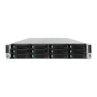
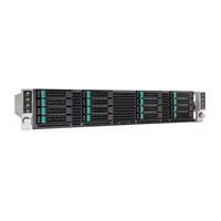
User Manuals: Intel H2000 Series Server Chassis
Manuals and User Guides for Intel H2000 Series Server Chassis. We have
2
Intel H2000 Series Server Chassis manuals available for free PDF download: Technical Product Specification, Service Manual
Intel H2000 Series Technical Product Specification (68 pages)
Server Chassis
Brand:
Intel
| Category:
Chassis
| Size: 1 MB
Table of Contents
Revision History
2
Table of Contents
4
1 Introduction
11
Chapter Outline
11
Server Board Use Disclaimer
12
2 Product Overview
13
Table 1. Chassis Feature Set
13
Table 2. Chassis SKU Matrix
13
Chassis Views
14
Figure 1. Chassis Overview (H2312Xx SKU)
14
Figure 2. Power Supply Scheme (Rear View)
14
Figure 3. Dummy Tray Cover
14
Chassis Dimensions
15
System Level Environmental Limits
15
Table 3. Chassis Dimension (SKU: H2312Xxjr/Kr)
15
Table 4. Chassis Dimension (SKU: H2216Xxjr/Kr)
15
Table 5. System Environmental Limits Summary
15
Chassis Parts
16
Figure 4. Major Chassis Parts
17
Hard Drive and Peripheral Bays
17
Figure 5. Intel Server Chassis H2312Xx Drive Bay Front View
18
Figure 6. Intel Server Chassis H2216Xx Drive Bay Front View
18
Figure 7. Chassis Bezel Front View
18
Front Bezel Support
18
Rack and Cabinet Mounting Options
18
3 Power Sub-System
20
Mechanical Overview
20
AC Power Supply Unit Dimension Overview
20
Figure 8. AC Power Supply Unit Dimension Overview
20
AC Power Supply Unit General Data
21
AC Input Connector
21
AC Power Cord Specification Requirements
21
Power Supply Unit DC Output Connector
21
Table 6. Specification Data for AC Power Supply Unit
21
Table 7. AC Power Cord Specification
21
Table 8. DC Output Power Connector
21
Handle Retention
22
LED Marking and Identification
22
Power Cage with Power Distribution Board
23
Table 9. Power Supply Status LED
23
Power Cage Output Pin Assignment
24
Figure 9. Power Cage Overview
24
Figure 10. Power Distribution Board
25
Table 10. Pin Assignment of Power Ouput Connector
25
AC Input Specification
26
Input Voltage and Frequency
26
AC Input Power Factor
26
Table 11. Pin Assignment of Control Signal Connector
26
Table 12. AC Input Rating
26
Efficiency
27
AC Line Fuse
27
AC Line Inrush
27
Table 13. Typical Power Factor
27
Table 14. Platinum Efficiency Requirement
27
AC Line Dropout/Holdup
28
AC Line Fast Transient (EFT) Specification
28
Hot Plug
28
Susceptability Requirements
28
Table 15. AC Power Holdup Reuqirement
28
Electrostatic Discharge Susceptibility
29
Fast Transient/Burst
29
Radiated Immunity
29
Surge Immunity
29
AC Line Transient Specification
29
Table 16. Performance Criteria
29
Power Recovery
30
Voltage Interruptions
30
AC Line Isolation
30
Table 17. AC Line Sag Transient Performance
30
Table 18. AC Line Surge Transient Performance
30
AC Power Inlet
31
DC Ouput Specification
31
Output Power/Currents
31
Figure 11. AC Power Cord Specification
31
Table 19. Load Ratings for Single Power Supply Unit
31
Standby Output
32
Voltage Regulation
32
Dynamic Loading
32
Table 20. Voltage Regulation Limits
32
Table 21. Transient Load Requirements
32
Capacitive Loading
33
Ripple/Noise
33
Grounding
33
Table 22. Capacitive Loading Conditions
33
Table 23. Ripple and Noise
33
Closed Loop Stability
34
Residual Voltage Immunity in Standby Mode
34
Common Mode Noise
34
Soft Starting
34
Zero Load Stability Requirement
34
Hot Swap Requirement
34
Forced Load Sharing
35
Timing Requirement
35
Table 24. Timing Requirement
35
Power Supply Cold Redundancy Support
36
Figure 12. Turn On/Off Timing (Power Supply Signals)
36
1200W CRPS Cold Redundancy
37
Table 25. 1200W CRPS Cold Redundancy Threshold
37
1600W CRPS Cold Redundancy
38
Control and Indicator Functions
38
PSON# Input Signal
38
Pwok(Power Good) Output Signal
38
Table 26. 1600W CRPS Cold Redundancy Threshold
38
Table 27. PSON# Signal Characteristics
38
Smbalert# Signal
39
Table 28. PWOK Signal Characteristics
39
Table 29. Smbalert# Signal Characteristics
39
Protection Circuits
40
Current Limit (OCP)
40
Over Voltage Protection (OVP)
40
Over Thermal Protection
40
Table 30. over Current Protection
40
Table 31. over Voltage Protection (OVP) Limits
40
Pmbus
41
PSU Address Lines A0
41
Figure 13. Power Supply Device Address
41
Accuracy
42
Table 32. PSU Addressing
42
Table 33. Pmbus Accuracy
42
Power Management Policy
43
Figure 14. Pmbus Monitoring Accuracy
43
Table 34. Power Management Policy
43
4 Cooling Sub-System
45
Power Supply Fan
45
Drive Bay Population Requirement
45
5 Hard Disk Drive Support
46
Hard Disk Drive Bays Scheme
46
Figure 15. HDD Scheme for H2312Xx
46
Figure 16. HDD Scheme for H2216Xx
46
Hard Drive Carrier
47
Hot-Swap Hard Drive Support
47
Figure 17. 3.5" HDD Assembly Overview
47
Figure 18. 2.5" HDD Assembly Overview
47
Backplane Block Diagram
48
Backplane Feature Set
48
3.5" Hot Swap Backplane Connector Scheme
49
Figure 19. Passive Backplane Block Diagram (for One Node)
49
Figure 20. 3.5" Backplane Component and Connectors (Front View)
49
2.5" Hot Swap Backplane Connector Scheme
50
Figure 21. 3.5" Backplane Component and Connectors (Back View)
50
Figure 22. 2.5" Backplane Component and Connectors (Front View)
51
Figure 23. 2.5" Backplane Component and Connectors (Back View)
51
Backplane LED Support
52
Figure 24. Hard Drive Carrier LED
52
Table 35. Hard Drive Carrier Status LED Functions
52
Table 36. Hard Drive Carrier Activity LED Functions
52
Backplane Connector Definition
53
Table 37. Backplane Input Power Connector Pin-Out
53
Table 38. 2-Blade Compute Node Power Connector Pin-Out
53
Table 39. 2X40 Pin Connector Pin-Out for Node Bridge Board
54
Table 40. Front Panel Connector Pin-Out
56
Table 41. Power Supply Control Connector Pin-Out
57
6 Front Panel Control and Indicators
58
Control Panel Button
59
Control Panel LED Indicators
59
Figure 25. Front Control Panel
59
Table 42. Front Control Button Function
59
Table 43. Front LED Indicator Functions
59
Power/Sleep LED
60
System Status LED
60
Table 44. Power LED Operation
60
Table 45. System Status LED Operation
60
System Status LED - BMC Initialization
62
Appendix A: Integration and Usage Tips
63
Glossary
64
Reference Documents
67
Advertisement
Intel H2000 Series Service Manual (54 pages)
Server Chassis
Brand:
Intel
| Category:
Chassis
| Size: 2 MB
Table of Contents
Important Safety Instructions
3
Instrucciones de Seguridad Importantes
3
Safety Information
3
Wichtige Sicherheitshinweise
3
About this Manual
5
Additional Information and Software
5
Manual Organization
5
Preface
5
Table of Contents
7
List of Tables
11
1 Server System Features
13
Server System Feature Overview
13
Figure 1. Intel Server Chassis H2000 Family (H2312Xx as Demonstrated)
13
Table 3. Intel ® Server Chassis H2000 Feature Summary
13
Server Chassis Parts
14
Figure 2. Intel Server Chassis H2000 Overview (H2312Xx as Demonstrated)
14
Figure 3. Front View of Intel
15
Figure 4. Front View of Intel
15
Figure 5. Rear View of Intel
15
Figure 6. HDD Array Scheme on Intel Server Chassis H2312Xx
15
Front Panel
16
Bezel
16
Figure 7. HDD Array Scheme on Intel
16
Figure 8. Front Panel Options
16
Figure 9. Front View of System Bezel
16
Hot-Swap SAS/SATA Backplane
17
Figure 10. 12 X 3.5-Inch Hard Drive Backplane Components (Front View)
17
Figure 11. 12 X 3.5-Inch Hard Drive Backplane Components (Rear View)
18
Figure 12. 16 X 2.5-Inch Hard Drive Backplane Components (Front View)
18
Dummy Tray Cover
19
Figure 13. 16 X 2.5-Inch Hard Drive Backplane Components (Rear View)
19
Figure 14. Dummy Tray Cover
19
2 Hardware Installations and Upgrades
20
Before You Begin
20
Tools and Supplies Needed
20
System Reference
20
Removing and Installing the Front Bezel
21
Removing the Front Bezel
21
Installing the Front Bezel
21
Figure 15. Removing the Front Bezel
21
Figure 16. Installing the Front Bezel
21
Removing and Installing the Chassis Top Cover
22
Removing the Chassis Top Cover
22
Installing the System Cover
22
Figure 17. Removing the System Top Cover
22
Removing and Installing the Compute Node Tray
23
Installing the Node Tray
23
Figure 18. Installing the System Cover
23
Figure 19. Removing Dummy Tray Cover
23
Removing the Node Tray
24
Figure 20. Installing the Node Tray
24
Removing and Installing the Redundant Power Supply Unit
25
Figure 21. Pulling out the Node Tray
25
Figure 22. Restore the Dummy Tray Cover
25
Installing the Power Supply Unit
26
Removing the Power Supply Unit
26
Installing and Removing Hot-Swap Hard Drive
26
Figure 23. Removing the PSU
26
Figure 24. Installing the PSU
26
Figure 25. Installing Hard Disk Drive - Installing 3.5" HDD to Carrier
27
Figure 26. Installing Hard Disk Drive - Inserting 3.5" HDD Assembly
27
Installing a Hard Disk Drive into 2.5" Hard Drive Carrier
27
Installing a Hard Disk Drive into 3.5" Hard Drive Carrier
27
Installing and Removing the 2.5" Backplane Board
28
Removing the 2.5" Backplane Board
28
Figure 27. Installing Hard Disk Drive - Installing 2.5" HDD to Carrier
28
Figure 28. Installing Hard Disk Drive - Inserting 2.5" HDD Assembly
28
Figure 29. Removing Power Cable Protective Cover
29
Figure 30. Removing the 2.5" Backplane Board
29
Installing the 2.5" Backplane Board
30
Figure 31. Align the Backplane to the Clamps on the Chassis Base
30
Figure 32. Installing the 2.5" Backplane Board
30
Installing and Removing the 3.5" Backplane Board
31
Removing the 3.5" Backplane Board
31
Figure 33. Installing Power Cable Protective Cover
31
Figure 34. Removing Power Cable Protective Cover
32
Figure 35. Removing the 2.5" Backplane Board
32
Installing the Server Board
33
Figure 36. Align the Backplane to the Clamps on the Chassis Base
33
Figure 37. Installing the 2.5" Backplane Board
33
Installing and Removing the Power Distribution Board
34
Removing the PDB
34
Figure 38. Installing Power Cable Protective Cover
34
Figure 39. Removing the Upper PDB
35
Figure 40. Removing the Lower PDB
35
Installing the PDB
36
Figure 41. Installing the Lower PDB
36
Replacing the Front Control Panel Board
37
Removing the Front Control Panel
37
Figure 42. Installing the Upper PDB
37
Figure 43. Removing FP Assembly from Rack Handle
38
Figure 44. Disconnecting Control Panel Cable
38
Installing Front Control Panel Board
39
Figure 45. Removing Control Panel Board
39
Figure 46. Installing Control Panel Board
40
Figure 47. Connecting Cable to Front Panel Board
40
Rack Mounting the Chassis
41
Intel ® AXXELVRAIL Rail Kit
41
Figure 48. Installing Control Panel Assembly to Rack Handle
41
Figure 49. Installing Inner Member of Rail Kit
42
Figure 50. Removing Inner Member from Slides
42
Mounting the Chassis to Rack
42
Figure 51. Installing Slides to Rack
43
Figure 52. Installing Inner Member to Chassis
43
Figure 53. Installing the Chassis to Rack
44
Figure 54. Extending Slides before Chassis Removal
44
Removing the Chassis from Rack
44
Figure 55. Removing the Chassis from Rack
45
Appendix A: Technical Reference
46
Power Supply Input Voltages
46
Power Supply Output Voltages
46
System Environmental Specifications
46
Table 4. CRPS Input Voltage
46
Table 5. CRPS Output Voltage
46
Table 6. System Environmental Limits Summary
46
Appendix B: Regulatory and Compliance Information
48
Appendix C: Getting Help
49
Warranty Information
49
Appendix D: Intel Server Issue Report Form
50
Advertisement
Related Products
Intel H2312 Series
Intel H2216 Series
Intel H2312JF
Intel H2216JF
Intel H2000WP
Intel H2000JF
Intel H2000G Series
Intel H2216JFQJR
Intel H2216JFFKR
Intel Astor II
Intel Categories
Motherboard
Computer Hardware
Server
Server Board
Desktop
More Intel Manuals
Login
Sign In
OR
Sign in with Facebook
Sign in with Google
Upload manual
Upload from disk
Upload from URL