Table of Contents
Advertisement
Quick Links
User Guide
6622-2221
29000447
MR-210/260/270
MR -21 0
GPR S
SIGN AL
PWR
LAN
WAN
NET
SIM
DAT
DTE
AN T.
(AU X.)
9-4 8V
DC
AS Y 0
MR -26 0
AN T.
(AU X.)
9-4 8V
DC
MR -27 0
LAN
3G/G PRS
SIGN AL
PWR
0
1
2
3
WLA N
DTE
NET SIM
DAT
AN T. WW AN
(Ma in)
11-5 8V DC
AN T. WW AN
1,3 A
(Au x.)
MA IN
AU X.
AS Y 0
LA N3
LA N2
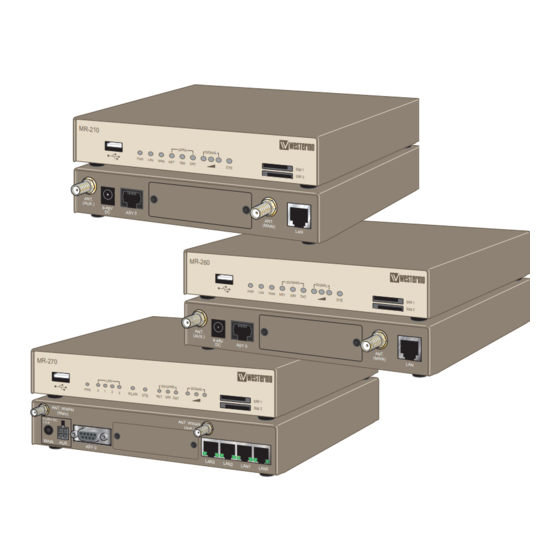
MR-210
GSM/GPRS Router
MR-260
GSM/GPRS/Edge/3G/
HSDPA/HSUPA Router
MR-270
GSM/GPRS/Edge/3G/
HSDPA/HSUPA Router
www.westermo.com
SIM 1
SIM 2
AN T.
(M AIN )
LA N
3G/G PRS
SIGN AL
PWR
LAN
WAN
NET
SIM
DAT
DTE
SIM 1
SIM 2
AS Y 0
AN T.
(M AIN )
LA N
SIM 1
SIM 2
LA N1
LA N0
Advertisement
Table of Contents

Related Manuals for Westermo MR-210


Summary of Contents for Westermo MR-210
- Page 1 User Guide 6622-2221 MR-210/260/270 29000447 MR -21 0 GPR S SIGN AL SIM 1 SIM 2 AN T. (AU X.) 9-4 8V AS Y 0 AN T. (M AIN ) LA N MR -26 0 3G/G PRS SIGN AL SIM 1 SIM 2 AN T.
-
Page 2: Legal Information
Under no circumstances shall Westermo be responsible for any loss of data or income or any special, incidental, and consequential or indirect damages howsoever caused. -
Page 3: Before Installation
Do not use or store the unit in dusty, dirty areas, connectors as well as other mechanical part may be damaged. If the unit is not working properly, contact the place of purchase, nearest Westermo distributor office or Westermo Tech support. - Page 4 General Remember to follow any special regulations and warnings in force in any area and never use the unit whenever it’s forbidden to use it. Do not use the unit when it may cause interference or danger. A wireless device exposed to interference above specified limits could result in deteriorated performance.
-
Page 5: Maintenance
For Vehicles equipped with an airbag An air bag inflates with great force. DO NOT place objects, including either installed or portable wireless equipment, in the area over the air bag or in the air bag deployment area. If in-vehicle wireless equipment is improperly installed and the air bag inflates, seri- ous injury could result. -
Page 6: Agency Approvals And Standards Compliance
Agency approvals and standards compliance Type Approval / Compliance EN 55024, EN 55024 A1, EN 55024 A2, Electromagnetic compatibility - Immunity IT equipment EN 55022, EN 55022 A1, Information technology equipment. Radio disturbance characteristics. Limits and methods of measurement FCC part 15 Class B Safety IEC / EN 60950-1, IT equipment Article 3.1a... -
Page 7: Declaration Of Conformity
Declaration of Conformity, MR-210 Westermo Teleindustri AB Declaration of conformity The manufacturer Westermo Teleindustri AB SE-640 40 Stora Sundby, Sweden Herewith declares that the product(s) Type of product Model Art no Cellular router MR-210 EDGE 3622-0201 is in conformity with the following EC directive(s). - Page 8 Declaration of Conformity, MR-260 Westermo Teleindustri AB Declaration of conformity The manufacturer Westermo Teleindustri AB SE-640 40 Stora Sundby, Sweden Herewith declares that the product(s) Type of product Model Art no Cellular router MR-260 3G 3622-0202 is in conformity with the following EC directive(s).
- Page 9 Declaration of Conformity, MR-270 Westermo Teleindustri AB Declaration of conformity The manufacturer Westermo Teleindustri AB SE-640 40 Stora Sundby, Sweden Herewith declares that the product(s) Type of product Model Art no Cellular router MR-270 3G 3622-0205 is in conformity with the following EC directive(s).
-
Page 10: Type Tests And Environmental Conditions
AC power ports Class B EN 55022 DC power ports Class B Temperature Operating MR-210 / MR-260 –20 to +55º Celsius (–25 to +70ºC restricted operation) –4 to +131º Fahrenheit (–13 to +158ºF restricted operation) MR-270 0 to +55º Celsius (0 to +70ºC restricted operation) -
Page 11: Dimensional Drawing
SIM-card! Dimensional drawing MR-210 and MR-260 uses the same casing. The only difference is the number of antenna connectors where the MR-260 has two instead of just one for the MR-210. -
Page 12: Interface Specifications
Interface specifications Power Rated voltage / MR-210 / MR-260 9 – 48 VDC Operating voltage MR-270 11 – 58 VDC Rated current (max) 1500 mA @ 12 VDC Rated frequency RS-232 Electrical specification EIA RS-232 Data rate 300 bit/s – 115.2 kbit/s... - Page 13 Antenna Frequency bands 850 MHz – 2100 MHz Connection SMA female, impedance: 50 ohm Electrical specification 3 volts SIM supported Number of slots Electrical specification USB 2.0 host interface Data rate Up to 12 Mbit/s (full-speed mode) Circuit type SELV Maximum supply current 500 mA in total for both ports Connection...
-
Page 14: Connector Description
Connections, MR-210 and MR-260 SIM Card Sockets The two sockets at the left side of the front panel are for the GSM SIM card(s) that you will receive from your service providers. SIM 1 and SIM 2 cannot be used to access two networks simultaneously. - Page 15 Connections, MR-270 SIM Card Sockets The two sockets at the left side of the front panel are for the GSM SIM card(s) that you will receive from your service providers. SIM 1 and SIM 2 cannot be used to access two networks simultaneously. The SIM card(s) should be inserted into SIM cardholders on the right of the front panel as illustrated below.
- Page 16 Description of AUX-connector and I/O signal lines The auxiliary power connector has two programmable signal lines. One is an input line, the other can be configured as either an input line or an output line. The mode of opera- tion of the input/output line is configurable through the CLI. The signal lines can be wired as shown in the following diagrams POWER Switch...
- Page 17 If the auxilary power connector is being used, the main power connector should NOT be used. POWER Switch Relay INPUT/OUTPUT 11 – 28 V INPUT – 1 Input, 1 Output, Supply Voltages up to 28 VDC POWER Switch Relay INPUT/OUTPUT 4 –...
-
Page 18: Led Status Description
LED Indicators MR-210 / MR-260 Status Description Unit has no power GREEN All OK Lit until unit has started up No link GREEN Link established GREEN FLASH Data traffic indication No Service 1 BLINK GPRS Mode 2 BLINKS EDGE Mode... -
Page 19: Led Status
LED Indicators MR-270 Status Description Unit has no power GREEN All OK Lit until unit has started up LAN 0,1,2,3 No link GREEN Link established GREEN FLASH Data traffic indication WLAN No connection on serial port, or no data is transmitted or received on the serial port GREEN Terminal connected to the serial port and the DTR signal... - Page 20 Stateful inspection Firewall / ACL, NAT, 1:1 NAT, Port Forwarding IPSec VPN including failover functionality, PSK & X.509, SCEP MR-210 / MR-260 • Encryption package needed, see first page for details. • 5 Non-encrypted tunnels included, supports 50 tunnels in total with upgrade.
- Page 21 Manageability Management tools • Web interface (HTTP and HTTPS) • Command Line Interface (CLI) via console port, SSHv2 and TELNET • SNMPv1/v2c/v3 • Powerful Packet/Protocol Analyzer with PCAP-export support • Flexible management of configuration and log files • Local file management via HTTP, FTP, TFTP and SCP •...
-
Page 22: Factory Default/Reset
IP address (Ethernet ports) 192.168.2.200 Netmask (Ethernet ports) 255.255.255.0 Username admin Password westermo Required information from SIM-provider/Carrier SIM PIN number Some providers do not use PIN numbers Access Point Name (APN) Server for network access APN username Some providers do not use APN authentication. - Page 23 Step-by-step guide to configure a GPRS/3G/HSPA connection using the web interface Antenna connectors ANT. ANT. (MAIN) (AUX.) 9-48V ASY 0 PC/Ethernet Power Connection connection (RJ-45) Antenna connectors ANT. WWAN ANT. WWAN (Main) (Aux.) 11-58V DC 1,3 A MAIN AUX. ASY 0 LAN3 LAN2 LAN1...
- Page 24 Please type in the following Username admin Password westermo Step 5 – Welcome screen You have now successfully logged into the unit and are ready to set up your mobile broadband connection. Please click on Network under the Configuration-menu item.
- Page 25 Step 6 – Mobile Setup First click on Mobile under the Interface-context and then click on Mobile Settings. Then fill in the Service Plan / APN and the SIM PIN number, if the card uses that. 6622-2221 • 29000447...
- Page 26 It is also recommended to enable the firewall on the unit. However, in some applica- tions there might be a need to open up the firewall for certain protocols, please refer to the reference guide for further information on how to administer the firewall. To activate your configuration please press Apply.
- Page 27 In your Internet browser type in www.westermo.com and test your connection, you should be able to see the Westermo website. You are now ready to use the MR-210 / MR-260 / MR-270! Change the IP address of the unit First follow steps 1 through 5 above.
- Page 28 Tel: +86 21 6145 0400 • Fax: +86 21 6145 0499 Tel: +33 1 69 10 21 00 • Fax: +33 1 69 10 21 01 sales.cn@westermo.com • www.cn.westermo.com infos@westermo.fr • www.westermo.fr Westermo Teleindustri AB have distributors in several countries, contact us for further information.
Need help?
Do you have a question about the MR-210 and is the answer not in the manual?
Questions and answers