Table of Contents
Advertisement
Quick Links
Advertisement
Table of Contents

Related Manuals for Westermo MRD-315


Summary of Contents for Westermo MRD-315
- Page 1 MRD-315, MRD-415, MRD-355 & MRD-455 Industrial Cellular Router...
- Page 2 6623-2250...
-
Page 3: General Information
Under no circumstances shall Westermo be responsible for any loss of data or income or any special, incidental, and consequential or indirect damages howsoever caused. -
Page 4: Safety Information
Safety information Before installation: Read this manual completely and gather all information on the unit. Make sure that you understand it fully. Check that your application does not exceed the safe operating specifications for this unit. This unit should only be installed by qualified personnel. This unit should be built-in to an apparatus cabinet, or similar, where access is restricted to service personnel only. -
Page 5: Care Recommendations
Do not use or store the unit in dusty or dirty areas, connectors as well as other mechanical part may be damaged. If the unit is not working properly, contact the place of purchase, nearest Westermo distributor office or Westermo Tech support. Maintenance No maintenance is required, as long as the unit is used as intended within the specified conditions. -
Page 6: Simplified Eu Declaration Of Conformity
Simplified EU declaration of conformity Hereby, Westermo declares that the equipment is in compliance with applicable EU directives. The full EU declaration of conformity and other detailed information are available at the respective product page at www.westermo.com.. Agency approvals and standards compliance... -
Page 7: Type Tests And Environmental Conditions
RF field AM modulated IEC 61000-4-3 10 V/m (80 – 2700 MHz) Enclosure Fast transient EN 61000-4-4 ± 1 kV Signal MRD-315/415/355 ports ± 2 kV MRD-455 ± 2 kV Power ports Surge EN 61000-4-5 ± 1 kV (Crit. B) -
Page 8: Product Description
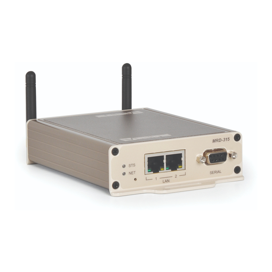
MRD-315 and MRD-415 The MRD-315 and MRD-415 comes in a very slim and robust casing which is ideal for wall mounting in small spaces, taking up very little space in a cabinet or similar. Connections come out on each end of the unit, with antenna connectors on one side and Ethernet and Serial interfaces on the other. - Page 9 Interface specifications for all MRDs Power Rated voltage 12 – 48 VDC Operating voltage 10 – 60 VDC Rated frequency Start-up current (max) 400 mA Polarity Reverse polarity protected Isolation to All other* Connection Detachable screw terminal Shielded cable Not required Ethernet TX Electrical specification IEEE std 802.3.
- Page 10 Connection 9 pin D-sub female Shielded cable Not required Conductive housing Number of ports Cellular interface Technology MRD-315 & MRD-355 MRD-415 MRD-455 Frequency band (MHz) Frequency band (MHz) Frequency band (MHz) GSM: GPRS, EDGE GSM 850, GSM 900, GSM 900, DCS 1800...
- Page 11 Protocols and Functionality Ethernet Technologies IEEE 802.3 for 10BaseT IEEE 802.3u for 100BaseTX Serial Port Technologies RS-232 Serial Over IP (Serial Extender and Virtual Serial Port) Router emulation AT command interpreter MODBUS DNP3 Layer-2 QoS IEEE 802.1p Class of Service IP Routing, Static IP routing Firewall,...
- Page 12 Hardware Overview Position Description Position Description LED indicators Power connector Antenna Connectors Serial Port SIM-card drawer(s) Ethernet TX ports Protective Earth Factory Reset Switch Connector Pinout Ethernet The Ethernet ports are on the front of the unit and are marked LAN 1 and LAN 2, each port has a LED indicating the connection speed and a LED indicating activity as shown in figure below.
-
Page 13: Led Indicators
DC connection Product Position Direction Description marking Input Common Input Supply voltage input DC Serial Port (DCE Female) Position Name Direction Description Data Carrier Detect Receive Data Transmit Data Data Terminal Ready – Signal Ground Data Set Ready Request to Send Clear to Send Ring Indicator LED Indicators... -
Page 14: Earth Connection
Snap on mounting, see figure. Mount the MRD-355 and MRD-455 with integrated DIN-clip: The MRD-315 and MRD-415 includes integrated mounting flanges and can be attached to a panel or tray by means of screws, using the slots provided. Alternatively the MRD- 315 and MRD-415 can be DIN rail mounted, using the DIN rail mounting kit. -
Page 15: Getting Started
IP address settings of the PC. Enter the following login details: • User Name: admin • Password: westermo • The Status summary page will be displayed. Installing the SIM Card … To eject the SIM card drawer, press the... -
Page 16: Power Supply
Antenna(s) The units have three antenna connectors (SMA). Please ensure that the connecting nut is done up tightly in order to make a good connection. Power Supply The MRD requires a DC power source in the voltage range of 10 to 60 VDC. The unit is designed to self protect from permanent damage if the voltage exceeds 60 VDC or if reverse polarity is applied. - Page 17 Dimensions MRD-315 and MRD-415 Measurements are stated in millimeters. 6623-2250...
- Page 18 Dimensions MRD-355 and MRD-455 Measurements are stated in millimeters. 6623-2250...
- Page 19 6623-2250...
- Page 20 Westermo • SE-635 35 Stora Sundby, Sweden Tel +46 16 42 80 00 Fax +46 16 42 80 01 E-mail: info@westermo.com www.westermo.com REV. F 6623-2250 2019-10 Westermo Network Technologies AB, Sweden...
Need help?
Do you have a question about the MRD-315 and is the answer not in the manual?
Questions and answers