Table of Contents
Advertisement
Quick Links
Advertisement
Table of Contents

Subscribe to Our Youtube Channel
Related Manuals for Westermo RT-370


Summary of Contents for Westermo RT-370
- Page 1 RT-370 User Guide REV. A 6623-2280 2018-03 Westermo Teleindustri AB, Sweden...
- Page 2 RT-370 User Guide Version History Version Date Comments 2018-03 First version License and copyright for included Free/Libre Open Source Software This product includes software developed by third parties, including Free/Libre Open Source Software (FLOSS). The specific license terms and copyright associated with the software are included in each software package respectively.
-
Page 3: Table Of Contents
5.1 LED Indicators During Power Up Sequence ................... 29 5.2 Connecting the service Ethernet ......................29 5.2.1 Service Ethernet Port Features ......................30 5.3 RT-370 Factory Reset Interface, Process for Factory Reset ..............31 5.3.1 Factory Reset Adapter Specification ....................31 5.3.2 Factory Reset Procedure ......................... 32 6 Maintenance .............................. - Page 4 RT-370 User Guide Figures and Tables Figure 1 RT-370 ................................6 Figure 2 RT-370 Block diagram ..........................6 Figure 3 Product identification label position ......................11 Figure 4 Product identification label example ......................11 Figure 5 Product label example ..........................12 Figure 6 RT-370 Mechanical overview ........................
-
Page 5: Foreword
RT-370 User Guide 1 Foreword This document describes the Installation procedure of the RT-370 device. 1.1 References Title Software Management Guide RT-370 Datasheet 1.2 Abbreviations and Terms Abbreviation Description Access Point BSSID Basic Service Set ID Electro Magnetic Compatibility Ethernet... -
Page 6: Rt-370 Introduction
RT-370 User Guide 2 RT-370 Introduction The RT-370 is a wireless communication product, developed for demanding industrial and railway applications. It is a radio device operating at 2.4 and 5 GHz WLAN bands, and can be configured as Access Point. -
Page 7: Supported Product Versions, Variants And Sw
RT-370 User Guide 2.1 Supported Product Versions, Variants and SW Supported product versions, variants and SW: Specification Value Notes Product Versions/ Variants RT-370 Software Version V6.6 and higher Table 1 Supported product versions, variants and SW 2.2 Important Safety Notes Notice The optical fast Ethernet interface of this device uses a class 1 laser product. -
Page 8: Delivery Content
RT-370 User Guide 2.3 Delivery Content The delivery consists of following main components: Description Number of Parts Notes RT-370 Connector Dust Cap Temporary protection of connectors: 1 plastic cap for FO connector 1 plastic cap for ETH connector 4 plastic caps for antenna connectors Table 3 Delivery content 2.4 Installation Countries... -
Page 9: Regulatory Notices
RT-370 User Guide 2.5 Regulatory Notices Caution! Any changes or modifications shall be approved by the party responsible for compliance. If not, users could void the user's authority to operate the equipment. Country code and antenna gain needs to be set properly for correct functionality in the installed country. -
Page 10: Certified Antennas For Fcc And Ic
5 GHz: 12 dBi max 1, 2 Table 5: FCC and IC certified antennas 2.6 Output power limitations The RT-370 has following output power limitations for ambient temperatures from -40°C to +70°C. Active antennas Max. output power 22 dBm per chain... -
Page 11: Rt-370 Identification And Version Information
RT-370 User Guide 2.7 RT-370 Identification and Version Information Product identification information is available at the product label. The product label is fixed to the device. Figure 3 Product identification label position Figure 4 Product identification label example Specification Value... -
Page 12: Figure 5 Product Label Example
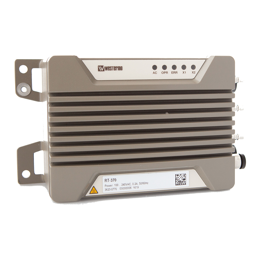
RT-370 User Guide At the rear side of the product further product specific information is printed to a second label. Figure 5 Product label example Specification Value Notes Product Name RT-370 Part Number 3623-0770 Max current 0.2 A Information on input current... -
Page 13: Technical Features
RT-370 User Guide 3 Technical Features Technical features are described in the reference document [2]. 4 Installation 4.1 Installation Procedure, Overview Order of Installation Step Description 1. Fixing The product is fixed in operating environment, ensuring that the environment complies with the installation environment constrains. See chapter 4.2 2. -
Page 14: Dimensions For Fixing Points
RT-370 User Guide 4.2 Dimensions for Fixing Points 4.2.1 Mechanical Overview Figure 6 RT-370 Mechanical overview Page 14 (34) - Page 15 RT-370 User Guide Parameter Value Notes Maximum dimensions 195 x 110 x 86.3 mm Without cables Maximum dimensions, with cables App 320 x 110 x 87 mm Space needed for installation but not including antennas Clearance 300 mm For cabling...
-
Page 16: Mechanical Integration, Fixing Points And Connector Positions
M6 screws/ 6 mm screw, screw length to be selected by installer based on installation screws environment and device weight Clearance Slot holes require a clearance of min. 10 mm at the long side of the RT-370 for correct installation and removal. Clearance for heat transfer is to be considered separately. Connector AC POWER... -
Page 17: Considerations When Mounting The Device
The protective housing still needs to ensure air circulation around the product. 4.3.5 Ambient Operating Temperature Range The RT-370 includes a vent allowing controlled air exchange due to temperature changes. Humidity is blocked by the vent. To ensure correct operation over the whole specified temperature range, certain aspects need to be considered. -
Page 18: Installations At Very High Temperatures
RT-370 User Guide temperature alarms shall be immediately rectified. See reference document [1] for detailed specification of the temperature sensors alarms. • The internal temperature alarms are adjusted so that the device supports the operating ambient temperatures for the nominal application scenario, i.e. considering typical power consumption of 7 W •... -
Page 19: Figure 10 Improved Heat Transfer Based On Fixing Plate
RT-370 User Guide When operating at ambient temperatures above app. +60C it is recommended to mount the product to a metallic base plate to improve the heat dissipation. The base plate increases the surface to spread the heat. Figure 10 Improved heat transfer based on fixing plate... -
Page 20: Connecting The System Grounding
For a safe operation and proper protection against lightning, both protective earth contacts of RT-370 must be connected to system ground. The grounding must be done always as a first step before connecting any other external interfaces to the product For the grounding at the M5 stud, a wire with a cross section of at least 6.0 mm... -
Page 21: Connecting The Rf Antenna Interfaces
Connector Type: N50 – Female Connector body: RF ground Table 13 Pinning: RF antenna connector 4.5.1 RF Antenna Interface Operation Modes RT-370 has four antenna interfaces. The antenna interfaces are operating independently of each other. Antenna Function Operation Notes Antenna 1 is used for both transmitting The antenna A1 shall be used. -
Page 22: Monitoring Antenna Rf Connector
RT-370 User Guide 4.5.2 Monitoring Antenna RF Connector The antenna A4 is the antenna port used for monitoring of the RF spectrum. Connect the monitoring antenna to A4 port. Figure 12 Monitoring antenna interface Page 22 (34) -
Page 23: Communication Antenna Rf Connectors
RT-370 User Guide 4.5.3 Communication Antenna RF Connectors The antenna interfaces A1, A2 and A3 are the antenna ports used for the communication link. Connect the antennas to those ports. Figure 13 Communication antenna interfaces NOTICE: If only one of the communication antennas is used, the antenna port A1 MUST be used. Otherwise the device is not operating correctly. -
Page 24: Connecting The Fiber Optical Cable
RT-370 User Guide 4.6 Connecting the Fiber Optical Cable The fiber optical Ethernet interface is a 1310nm single mode optical interface. The optical connector is an ODC-2 type. Figure 14 Fiber optic ETH interface Signal Name, Function Notes TX (transmitting) Connector Type: H&S ODC-2... -
Page 25: Connecting The Ac Power Feed
RT-370 User Guide 4.7 Connecting the AC Power Feed The power feed is connected to the AC power feed connector. NOTICE: The installation of the AC power must be done by trained professionals. It must be ensured that there is no power applied to the AC wires during the installation work. - Page 26 RT-370 User Guide Parameter Value Notes Nominal voltage range 100 V…240 V, 50/60 Hz Min/max voltage range 90..264 VAC Guaranteed min/max operating voltage range Power consumption App. 8.5 W / 18.5 VA Idle load App. 10 W / 20.0 VA...
-
Page 27: Power Consumption Examples
RT-370 User Guide 4.7.1 Power Consumption Examples The power consumption is dependent on the operational parameters, like RF output power, amount of routed traffic and the RX duty cycle. Test case Antennas TX duty TX output Amb. Avg. Power 100 VAC cycle Temp. - Page 28 RT-370 User Guide Test case Antennas TX duty TX output Amb. Avg. Power 230 VAC cycle Temp. 2.4 GHz idle 1x1, 2x2, 3x3 1…3 x 22 dBm -40°C P = 7.06 W/ 11.96 VA 2.4 GHz idle 1x1, 2x2, 3x3 1…3 x 22 dBm...
-
Page 29: Outdoor Radio Access Point Configuration And Use
RT-370 User Guide 5 Outdoor Radio Access Point Configuration and Use The complete configuration process is described in reference document [1]. 5.1 LED Indicators During Power Up Sequence LED behavior during power-up sequence is described in reference document [1] chapter Status Indication. -
Page 30: Service Ethernet Port Features
RT-370 User Guide Figure 17 Service 1000Base-TX interface The connectors should be assembled with correct torque (appr. 1.0 Nm, check connector manufacturer data). NOTICE: The service Ethernet Interface connector fulfills the IP-protection when the cable plug or the dust cap is connected. -
Page 31: Rt-370 Factory Reset Interface, Process For Factory Reset
1000BASE-T, 100BASE-T and 10BASE-T operation. For final installation the use of auto-negotiation is however not recommended. 5.3 RT-370 Factory Reset Interface, Process for Factory Reset A factory reset is not typically needed for the installation. It is required if the device configuration is lost and the device shall be set to a known configuration. -
Page 32: Factory Reset Procedure
RT-370 User Guide 5.3.2 Factory Reset Procedure The Factory Reset is performed with a factory reset adapter that is connected to the service Ethernet port during the start-up. Step Description Plug the factory reset adapter to the service Ethernet interface. -
Page 33: Maintenance
Polyamide 6 (PA6) Polytetrafluoroethylene (PTFE) Stickers Autotex XE The resistance to chemicals of the materials mentioned above has been communicated. For guidance which cleaning liquids are allowed for the cleaning of the product, Westermo is to be contacted. Page 33 (34) -
Page 34: Troubleshooting Based On Functional Behavior
RT-370 User Guide 6.2 Troubleshooting Based on Functional Behavior Please read the troubleshooting instructions in reference document [1]. 6.3 Repair Work The product is exchanged as a whole. On module level no repair work is done in the field. Broken units need to be returned to the supplier for repair.
Need help?
Do you have a question about the RT-370 and is the answer not in the manual?
Questions and answers