Westermo SDW-550 User Manual
6644-2230
industrial ethernet
5-port switch
Hide thumbs
Also See for SDW-550:
- User manual (21 pages) ,
- User manual (23 pages) ,
- User manual (25 pages)
Table of Contents
Advertisement
Quick Links
Advertisement
Table of Contents

Related Manuals for Westermo SDW-550


Summary of Contents for Westermo SDW-550
- Page 1 User Guide SDW-550 6644-2230 Industrial Ethernet 5-port Switch www.westermo.com...
-
Page 2: Table Of Contents
3.1 Declaration of Conformity ..............................4. Specification ........................................ 5. Maintenance ........................................ 6. Installation ........................................6.1 Mounting / Removal ..................................6.2 Connections ......................................6.2.1 Power ......................................6.2.2 TX ........................................11–13 6.3 DIP switch settings SDW-550 ........................... 6.5 LED indicators ....................................6644-2230... -
Page 3: Description
TX port. It is also possible to set up one port to monitor traffic to/from the switch. The SDW-550 has been designed to meet high industrial specifications, providing very high dependability in harsh environmental conditions. Features: …... -
Page 4: Safety
2. Safety General: Before using this unit, read this manual completely and gather all information on the unit. Make sure that you understand it fully. Check that your application does not exceed the safe operating specifications for this unit. Before installation, maintenance or modification work: Prevent damage to internal electronics from electrostatic discharges (ESD) by discharging your body to a grounding point (e.g. -
Page 5: Approvals
Do not use or store the unit in dusty, dirty areas, connectors as well as other mechanical part may be damaged. If the unit is not working properly, contact the place of purchase, nearest Westermo dis- tributor office or Westermo Tech support. -
Page 6: Declaration Of Conformity
3.1 Declaration of Conformity Westermo Teleindustri AB Declaration of conformity The manufacturer Westermo Teleindustri AB SE-640 40 Stora Sundby, Sweden Herewith declares that the product(s) Type of product Model Art no Installation manual DIN-rail SDW-550 3644-0001 6644-2230 is in conformity with the following EC directive(s). -
Page 7: Specification
4. Specification Power interface SDW-550 Rated voltage 12–48 VDC, polarity protected Operating voltage 9.6 – 57.6 VDC Rated current @12 VDC power input 320 mA Rated frequency Connection Detachable screw terminal Connector size 0.2 – 2.5 mm (AWG 24-12) Ethernet TX Interface Electrical specification IEEE std 802.3. -
Page 8: Maintenance
5. Maintenance No maintenance is required, as long as the unit is used as intended within the specified conditions. 6. Installation 6.1 Mounting / Removal Before mounting or removing the unit: Prevent damage to internal electronics from electrostatic discharges (ESD) by discharging your body to a grounding point (e.g. -
Page 9: Connections
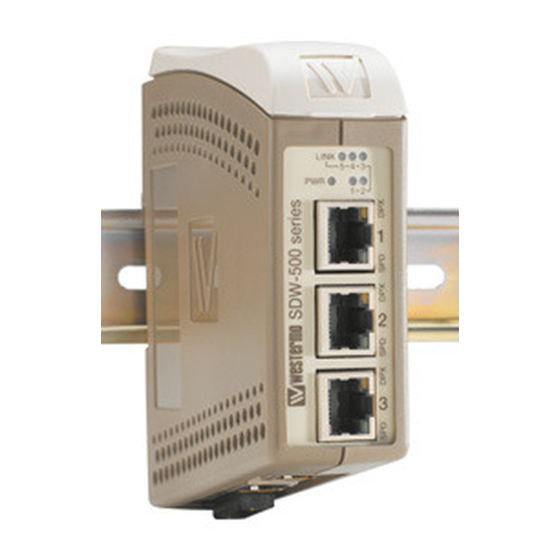
6.2 Connections LED indicators Network RJ-45 connection Network RJ-45 connection Power connection Available models: … SDW-550 10/100Base-T/TX: 5 ports 6644-2230... -
Page 10: Power
6.2.1 Power The SDW-550 supports 3-pos screw terminal Description redundant power connection. The positive input are +VA and +VB, the negative input for both supplies are COM. The power is drawn from the input with the highest voltage. 6.2.2 TX Ethernet TX connection (RJ-45 connector), automatic MDI/MDI-X crossover. -
Page 11: Dip Switch Settings Sdw-550
6.3 DIP switch settings SDW-550 DIP-switches are accessible under the lid on top of the unit. DIP-switches are used to configure the unit. Warning! Prevent damage to internal electronics from electrostatic discharges (ESD) by discharging your body to a grounding point (e.g. use of wrist strap), before the lid on top/front of the unit is removed. - Page 12 Port 1 settings Port 3 settings Auto-negotiation and Auto-negotiation and auto MDI/MDI-X disabled auto MDI/MDI-X disabled 1 2 3 4 5 6 7 8 1 2 3 4 5 6 7 8 Auto-negotiation and Auto-negotiation and auto MDI/MDI-X enabled auto MDI/MDI-X enabled 1 2 3 4 5 6 7 8 1 2 3 4 5 6 7 8 10 Mbit/s speed selected...
-
Page 13: Factory Settings
Port 5 settings Port mirroring settings Auto-negotiation and No monitoring selected auto MDI/MDI-X disabled 1 2 3 4 5 6 7 8 1 2 3 4 5 6 7 8 Auto-negotiation and Monitoring selected auto MDI/MDI-X enabled 1 2 3 4 5 6 7 8 1 2 3 4 5 6 7 8 10 Mbit/s speed selected 1 2 3 4 5 6 7 8... -
Page 14: Led Indicators
6.5 LED indicators At power on the PWR flashes during initialising. Indicators (LED) Power (PWR) Link (LINK) of every port Speed (SPD) and duplex (DPX) of TX ports Status Indication of Internal power, initialising OK Slow flash Initialisation progressing Fast flash Initialisation error LINK No Ethernet link... -
Page 15: Application Example
Tél : +33 1 69 10 21 00 • Fax : +33 1 69 10 21 01 Phone: +44(0)1489 580 585 • Fax.:+44(0)1489 580586 E-mail : infos@westermo.fr E-Mail: sales@westermo.co.uk Westermo Teleindustri AB have distributors in several countries, contact us for further information.
Need help?
Do you have a question about the SDW-550 and is the answer not in the manual?
Questions and answers