
Subscribe to Our Youtube Channel
Related Manuals for Westermo MRD-315


Summary of Contents for Westermo MRD-315
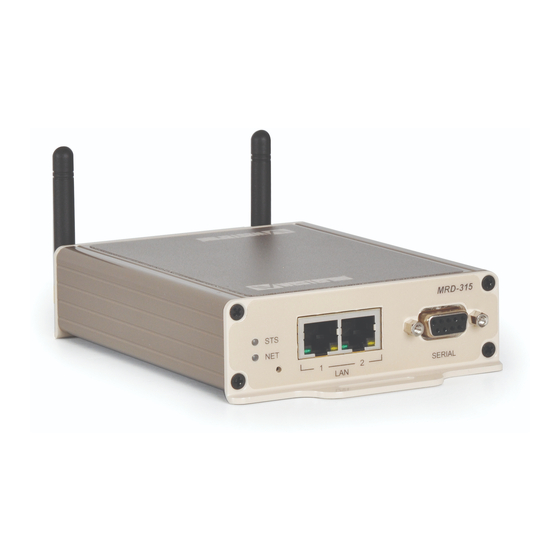
- Page 1 User Guide 6623-2250 MRD-315, MRD-355 & MRD-455 Industrial Mobile Broadband Router GSM / GPRS / EDGE / 3G / HSDPA / HSUPA / HSPA / 4G LTE www.westermo.com...
-
Page 2: Legal Information
Under no circumstances shall Westermo be responsible for any loss of data or income or any special, incidental, and consequential or indirect damages howsoever caused. -
Page 3: Before Installation
Do not use or store the unit in dusty, dirty areas, connectors as well as other mechanical part may be damaged. If the unit is not working properly, contact the place of purchase, nearest Westermo distributor office or Westermo Tech support. - Page 4 General Remember to follow any special regulations and warnings in force in any area and never use the unit whenever it’s forbidden to use it. Do not use the unit when it may cause interference or danger. A wireless device exposed to interference above specified limits could result in deteriorated performance.
-
Page 5: Maintenance
For Vehicles equipped with an airbag An air bag inflates with great force. DO NOT place objects, including either installed or portable wireless equipment, in the area over the air bag or in the air bag deployment area. If in-vehicle wireless equipment is improperly installed and the air bag inflates, serious injury could result. -
Page 6: Agency Approvals And Standards Compliance
Agency approvals and standards compliance Type Approval/Compliance EN 55022, EN 55022 A1, Information technology equipment. Radio disturbance characteristics. Limits and methods of measurement EN 55024, EN 55024 A1, EN 55024 A2, Electromagnetic compatibility – Immunity IT equipment Safety IEC/EN 60950-1, IT equipment Article 3.1a EN 60950-1 Safety... -
Page 7: Declaration Of Conformity
Declaration of Conformity, MRD 315 Westermo Teleindustri AB Declaration of conformity The manufacturer Westermo Teleindustri AB SE-640 40 Stora Sundby, Sweden Herewith declares that the product(s) Type of product Model Art no 3G Cellular Modem / Router MRD 315 3623-0050 is in conformity with the following EC directive(s). - Page 8 Declaration of Conformity, MRD 355 Westermo Teleindustri AB Declaration of conformity The manufacturer Westermo Teleindustri AB SE-640 40 Stora Sundby, Sweden Herewith declares that the product(s) Type of product Model Art no 3G Cellular Modem / Router MRD-355 3623-0250 is in conformity with the following EC directive(s).
- Page 9 Declaration of Conformity, MRD 455 Westermo Teleindustri AB Declaration of conformity The manufacturer Westermo Teleindustri AB SE-640 40 Stora Sundby, Sweden Herewith declares that the product(s) Type of product Model Art no 4G Cellular Modem / Router MRD-455 3623-0401 is in conformity with the following EC directive(s).
-
Page 10: Type Tests And Environmental Conditions
Storage & Transport 0 to 90% relative humidity non condensing. Altitude Operating 2000 m/70 kPa MTBF MIL-217-F MRD-315 825 759 hours MRD-355 689 933 hours MRD-455 689 933 hours Service life Operating 10 year Dimension W x H x D... - Page 11 (VPN), and features a simple, yet powerful, packet inspection firewall. For solar powered applications energy efficiency is vital and the MRD-315 has a special low-power mode to only be fully powered when needed. The built-in serial port offers a simple modem replacement solution with the benefit of not having to reprogram or change legacy components during an upgrade.
- Page 12 Description MRD-355 Remote access removes boundaries, eliminates the need for time consuming site visits and provide a network infrastructure suitable for today’s “always-on” society. The MRD-355 industrial mobile broadband GPRS/EDGE/3G router uses the Internet to cost effectively inter-connect systems, allowing HMI, PLCs, sensors etc to communicate with each other.
- Page 13 Description MRD-455 Remote access removes boundaries, eliminates the need for time consuming site visits and provide a network infrastructure suitable for today’s “always-on” society. The MRD-455 industrial mobile broadband GPRS/ EDGE/3G/4G LTE router uses the Internet to cost effectively inter-connect systems, allowing HMI, PLCs, sensors etc to communicate with each other.
- Page 14 General interface specifications for all MRDs RS-232 Electrical specification EIA RS-232 Data rate 300 bit/s – 115.2 kbit/s Data format 7 or 8 data bits, Odd, even or none parity, 1 or 2 stop bits Protocol Transparent, optimised by packing algorithm Circuit type SELV Transmission range...
- Page 15 - only MRD-455 Antennas Transmit Receive (RX) Required Label Connector (TX) Main Antenna MAIN Optional Antenna* RxDIV GPS Antenna** – – * Antenna connector labeled RxDIV is optional and used for receive diversity. ** Passive GPS antennas only. Electrical specification 3 volts SIM supported Number of slots MRD-315: 1 MRD-355: 2 MRD-455: 2 6623-2250...
- Page 16 Connections MRD-315 Antenna Protective earth Ethernet TX Connections (RJ-45 connector) LAN1-2 Position Direction Description In/Out In/Out TD– SIM card drawer Power SIM card drawer In/Out eject button connector – Not Connected – Not Connected In/Out RD– – Not Connected –...
- Page 17 Connections MRD-355 and MRD-455 Antenna Antenna connection Led indicators Ethernet TX Connections (RJ-45 connector) LAN1-2 Factory default reset switch Position Direction Description SIM card 2 drawer In/Out eject button In/Out TD– SIM card drawers In/Out – Not Connected SIM card 1 drawer –...
-
Page 18: Led Indicators
Network Indicator There are network indicators one for each SIM, i.e. MRD-315 (NET), MRD-355/455 (NET1, NET2) The indicator reports the status of the connection to the network. When powered up the indicator will be off, the indicator will then flash green whilst the unit searches for a network, once connected to the network the indicator will light green. -
Page 19: Factory Default Reset Switch
too low for a connection. When the unit is first switched on, or is reset the indicator will first light red, then flash red in sequence with the Status Indicator, this is normal behavior during boot-up and does not indicate a fault. Factory Default Reset Switch The reset switch is used to restore the configuration of the MRD to factory default settings. - Page 20 Protocols and Functionality MRD-315/355/455 Ethernet Technologies IEEE 802.3 for 10BaseT IEEE 802.3u for 100BaseTX Cellular Technologies Circuit Switched Data mode (CSD) GPRS Multi-slot class 12, mobile station class B, PBCCH support, coding schemes CS 1-4 EDGE Multi-slot class 12 (max 236.8 kbit/s), mobile station class B,...
-
Page 21: Getting Started
Getting started Installing the SIM Card SIM card drawer eject button … To eject the SIM card drawer, press the SIM card eject button using a suitable tool and remove the drawer, refer to figure for the location of the SIM card eject button. -
Page 22: Windows Pc Network Settings
Configuration Accessing and Using the Web Interface All configuration of the MRD can be done via the web interface. In order to view the web pages a computer with a fixed IP address, on the same sub-net as the MRD, will need to be connected to one of the LAN ports. - Page 23 Figure 1 6. The Internet Protocol (TCP/IP)Properties dialog box, change the settings to match those shown in Figure 2, and then click ”OK. Figure 2 Note: If a web browser was open prior to making the network changes, then it will need to be closed and re-started before attempting to connect to the MRD.
- Page 24 IP address settings of the PC. Enter the following login details: • User Name: admin • Password: westermo • The Status summary page will be displayed, it will be similar to Figure 3. Figure 3 Note: If the unit is not yet configured it is likely that the Network Status and Connection Status will indicate a fault condition.
-
Page 25: Basic Configuration
Basic Configuration The three sections below detail the steps needed to configure the MRD for basic packet mode functionality. For details on how to configure the unit for Circuit Switched mode and for more advanced configuration refer to the Advanced Configuration section of the Reference Guide. - Page 26 Adding a Network Connection Profile To access the wireless packet mode settings click on the ”Packet mode'' tab. The screen shown in Figure 6 will be displayed. The page shows the connection configuration details and is divided into two sections. The first section shows the current connection state for the selected profile.
- Page 27 Figure 7 Enter APN Enter dial string Set Authentication Enter username Enter password Click ”Update” to save profile Note: In order to set a password click the check-box marked New. The password can now be entered in the text field. The password is visible as it is being typed so that it can be checked for errors prior to being set.
-
Page 28: Enable The Wireless Connection
Enable the Wireless Connection To complete the configuration of the wireless connection, set the ”Connection state” to ”Always connect” and click the ”Update” button to save the changes. Once the changes have been set, the MRD will initiate a connection. Normally it will take up to 30 seconds to esablish a connection. -
Page 29: Enabling Dhcp
Configure the LAN interface and DHCP Server To access the configuration page for the LAN interface and DHCP Server, select ”Interfaces” from the top level menu. A LAN interface screen similar to the one shown in Figure 10 will be displayed. Figure 10 Setting the IP Address If it is desired to change the IP address of the LAN port, follow the steps below:... - Page 30 Under the ”DHCP Server Configuration table”: • Set the ”Enabled” option to ”Yes”. • Enter the first address of the group in the ”Start Address box”. • Enter the last address of the group in the ”End Address box”. • Enter a lease time for the ”Default Lease time”. •...
-
Page 31: Earth Connection
Mount the MRD-355 and MRD-455 with integrated DIN-clip: The MRD-315 includes integrated mounting flanges and can be attached to a panel or tray by means of screws, using the slots provided. Alternatively the MRD-315 can be DIN rail mounted, using the DIN rail mounting kit. - Page 32 Dimensions MRD-315 Measurements are stated in millimeters. 6623-2250...
- Page 33 Dimensions MRD-355 and MRD-455 Measurements are stated in millimeters. 6623-2250...
-
Page 34: Sales Units
Other Offices infos@westermo.fr sales@westermo.com.sg www.westermo.fr www.westermo.com Germany Sweden info@westermo.de info.sverige@westermo.se www.westermo.de www.westermo.se For complete contact information, please visit our website at www.westermo.com/contact or scan the QR code REV. B 6623-2250 2015-04 Westermo Teleindustri AB, Sweden – A Beijer Electronics Group Company...
Need help?
Do you have a question about the MRD-315 and is the answer not in the manual?
Questions and answers