Sign In
Upload
Download
Table of Contents
Contents
Add to my manuals
Delete from my manuals
Share
URL of this page:
HTML Link:
Bookmark this page
Add
Manual will be automatically added to "My Manuals"
Print this page
×
Bookmark added
×
Added to my manuals
Manuals
Brands
Westermo Manuals
Network Router
Lynx DSS
User manual
Westermo Lynx DSS User Manual
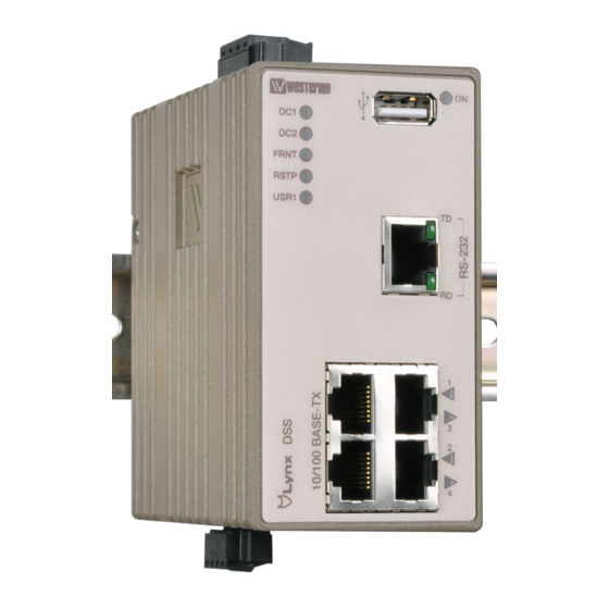
Industrial ethernet 5-port device server switch
Hide thumbs
Also See for Lynx DSS
:
User manual
(25 pages)
1
2
3
4
5
6
7
8
9
10
11
12
13
14
15
16
17
18
19
20
Table Of Contents
21
page
of
21
Go
/
21
Contents
Table of Contents
Bookmarks
Table of Contents
Software Tools
Legal Information
Before Installation
Care Recommendations
Maintenance
Agency Approvals and Standards Compliance
Declaration of Conformity
Type Tests and Environmental Conditions
Interface Specifications
Connection to Console Port
Accessories Description
Power Connection
Led Indicators
Led Status Description
Getting Started
Referring Documents
Document Number
Sales Units
Advertisement
Quick Links
1
Software Tools
Download this manual
User Guide
6643-2230
Lynx DSS
L105-S1/L205-S1
WeOS
Industrial Ethernet
5-port Device Server Switch
www.westermo.com
Table of
Contents
Previous
Page
Next
Page
1
2
3
4
5
Advertisement
Table of Contents
Need help?
Do you have a question about the Lynx DSS and is the answer not in the manual?
Ask a question
Questions and answers
Related Manuals for Westermo Lynx DSS
Switch Westermo Lynx DSS L108-F2G-S2 EX User Manual
Industrial ethernet 8-port device server switch (25 pages)
Switch Westermo Lynx L108-F2G-S2 User Manual
Industrial ethernet 8-port device server switch (36 pages)
Switch Westermo Lynx L108-F2G-S2 User Manual
Industrial ethernet 8-port device server switch (34 pages)
Switch Westermo Lynx L108-F2G-S2 User Manual
Industrial ethernet 8-port device server switch (32 pages)
Switch Westermo Lynx L105-S1 User Manual
Industrial ethernet 5-port device server switch (28 pages)
Switch Westermo Lynx DSS L206-S2 User Manual
Industrial ethernet 6-port device server switch (25 pages)
Switch Westermo Lynx DSS L106-S2 User Manual
Industrial ethernet 6-port device server switch (25 pages)
Switch Westermo Lynx DSS L108 User Manual
Industrial ethernet 8-port device server switch (21 pages)
Network Router Westermo L105-S1 User Manual
Industrial ethernet 5-port device server switch (21 pages)
Network Router Westermo Lynx L106-F2G User Manual
Industrial ethernet 6-port switch (17 pages)
Network Router Westermo Lynx Plus User Manual
Industrial ethernet 10-port switch (17 pages)
Network Router Westermo Lynx DSS L208-F2G-S2-EX User Manual
Industrial ethernet 8-port device server switch (32 pages)
Network Router Westermo LRW-112 Series Manual
Fibre optic industrial router for lonworks tp/ft-10 point-to-point, line and redundant ring (29 pages)
Network Router Westermo Lynx 5600 Series User Manual
Industrial gigabit switch (28 pages)
Network Router Westermo LA-10 Installation Manual
Line split unit (12 pages)
Network Router Westermo BRD-355 User Manual
Industrial adsl/vdsl router (21 pages)
This manual is also suitable for:
L205-s1
L105-s1
Lynx dss l108
Lynx dss l208-f2g-s2
Lynx dss l108-f2g-s2
L108-f2g-s2
...
Show all
L208-f2g-s2
Lynx dss l106-s2
Lynx dss l206-s2
L-106-s2 ex
L-206-s2 ex
Lynx dss l-105-s1 ex
Lynx dss l-205-s1 ex
Table of Contents
Print
Rename the bookmark
Delete bookmark?
Delete from my manuals?
Login
Sign In
OR
Sign in with Facebook
Sign in with Google
Upload manual
Upload from disk
Upload from URL


Need help?
Do you have a question about the Lynx DSS and is the answer not in the manual?
Questions and answers