Table of Contents
Advertisement
Quick Links
Advertisement
Table of Contents

Related Manuals for Westermo Merlin Series


Summary of Contents for Westermo Merlin Series
- Page 1 www.wester mo.com Merlin 4700 Series Industrial VDSL Cellular Router...
-
Page 2: Table Of Contents
Table of Contents 1. General Information ......................3 1.1. Legal Information ....................3 1.2. About This Guide ....................3 1.3. License and Copyright for Included FLOSS ............... 3 2. Safety and Regulations ...................... 4 2.1. Warning Levels ....................... 4 2.2. Safety Information ....................5 2.3. -
Page 3: General Information
Westermo reserves the right to revise this document or withdraw it at any time without prior notice. Under no circumstances shall Westermo be responsible for any loss of data or income or any special, incidental, and consequential or indirect damages howsoever caused. -
Page 4: Safety And Regulations
2. Safety and Regulations 2.1. Warning Levels Warning signs are provided to prevent personal injuries and/or damages to the product. The following levels are used: Level of warning Description Consequence personal Consequence material injury damage Indicates a potentially hazardous situation Possible death or major injury Major damage to the product WARNING... -
Page 5: Safety Information
(only valid for metallic housings). Westermo recommends a cross-sectional area of at least 4 mm Upon removal of the product, disconnect the product from the power supply and all other communication ports before disconnecting the protective earthing conductor. -
Page 6: Care Recommendations
If the product is used in a manner not according to specification, the protection provided by the equipment may be impaired. If the product is not working properly, contact the place of purchase, the nearest Westermo distributor office or Westermo technical support. -
Page 7: Compliance Information
Table 2. Agency approvals and standards compliance 2.5.2. Simplified Declaration of Conformity Hereby, Westermo declares that this product is in compliance with applicable EU directives and UK legislations. The full declaration of conformity and other detailed information is available at www.westermo.com/support/... -
Page 8: Product Description
This compact, rugged unit is suited to tight spaces. Its high MTBF and wide temperature range support maximum service life. To achieve best-in-class cybersecurity, the Merlin series is equipped with a TPM (Trusted Platform Module) chip that keeps cryptographic keys secure. Secure Boot ensures that the unit boots using only software that is signed and trusted by manufacturer. -
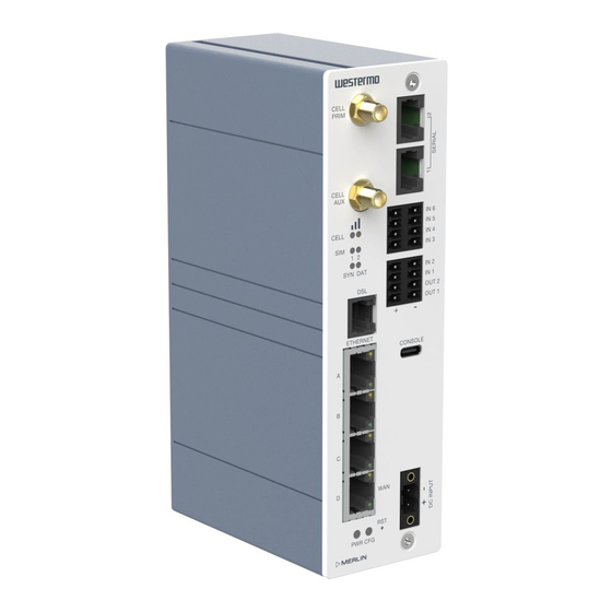
Page 9: Hardware Overview
3.3. Hardware Overview Figure 3. Location of interface ports and LEDs, illustrated by a Merlin-4708-V-T4G-S2-DI6-DO2-LV model Description Description Serial ports Digital I/Os USB-C Console port Power connection Reset button Power and configuration LEDs Ethernet RJ45 ports VDSL port DSL status LEDs SIM LEDs LTE signal strength LTE auxiliary SMA connector... -
Page 10: Digital I/O Interface
The positive input is marked with a plus sign, "+". The negative input is marked with a minus sign, "-". Connect the voltage to the + pin and the return to the - pin on the power input. NOTICE - POWER SUPPLY Where an AC/DC-adapter has not been supplied, a power supply of no greater than 100 W should be used, with a current limit of 1 Amp. -
Page 11: Dsl Port
RS-232 ports When you configure a serial port to operate as an RS-232 interface, it supports the following signals: • Transmit Data • Receive Data • CTS • RTS • DSR • DTR The pin numbering of the RJ45 socket, when viewed from the front of the unit, is as shown below. The RS-232 interface is wired as a DCE. -
Page 12: Antennas
Flashing slowly Releasing 20-30 seconds reboots the router to recovery mode. Only to be done in case of emergency and under the guidance of Westermo support staff. Note: this may wipe the configurations, both config1 and config2. > 30 seconds Solid on Releasing after 30 seconds performs a normal reset. -
Page 13: Led Indicators
3.5. LED Indicators The LED indicators described in this section are all single colour LEDs. When the router is powered on, the power LED is green. The possible LED states are: • Off • Flashing slowly • Flashing quickly • On Status Description Booting up... -
Page 14: Ethernet Port Led Behaviour
3.6. Ethernet Port LED Behaviour There are four Ethernet ports and each has a pair of LEDS: a LINK LED (green) and a SPEED LED (amber). When looking at the port, the LED on the bottom is the LINK LED, and the SPEED LED is on the top. Figure 7. -
Page 15: Installation
4. Installation 4.1. Mounting the Router The router is fitted with a DIN-rail clip by default. To attach the router to a DIN-rail: Position the router so that the spring of the DIN-clip rests on the DIN-rail. Push the router in an upward direction so that the spring of the DIN-clip compresses and the top hook of the DIN-clip slides and clamps to the DIN-rail. -
Page 16: Inserting Sim 1 Card
4.5.1. Inserting SIM 1 Card Ensure the router is powered off. • Remove the SIM cover using a suitable screwdriver. • Hold the SIM 1 card with the chip side facing down and the cut corner facing away from you, to the left. •... -
Page 17: Specifications
5. Specifications 5.1. Interface Specifications DC, Power port Operating voltage 9.6 to 60 VDC Rated current 580 mA at 12 VDC 170 mA at 48 VDC Rated frequency Inrush current 2.74 x 10 s at 12 VDC Polarity Reverse polarity protected Redundant power input Isolation All other ports... - Page 18 I/O connection, Relay output Maximum voltage/current 220 VDC/2A Connect resistance <100mΩ Isolation To all other ports Connector Detachable latch terminal Conductor cross section 0.14 - 1.5 mm² (AWG 28 - 16) Stripping length cable 7 mm Number of ports I/O connection, Digital input Maximum voltage/current 24 VDC Voltage levels...
-
Page 19: Type Tests And Environmental Conditions
5.2. Type Tests and Environmental Conditions Environmental Basic standard Description Test levels phenomena EN 61000-4-2 Enclosure Contact: ±4 kV Air: ±8 kV Radiated RF immunity EN 61000-4-3 Enclosure 10 V/m at (80 - 3000) MHz 5 V/m at (3 - 6) GHz 1 kHz sine, 80% AM Fast transients EN 61000-4-4... - Page 20 Environmental Basic standard Description Test levels phenomena Temperatures EN 60068-2-1 Operational -20 to +65°C EN 60068-2-2 Humidity EN 60068-2-30 Operational 5-95 % relative humidity MTBF Telcordia Ground benign, 25°C 1,500,000 hours Enclosure EN 62368-1 Aluminium Fire enclosure Weight 760 g Cooling Convection Refer to "Safety Information"...
-
Page 21: Revision Notes
2023-03-30 Added no-serial, no-digital variant Rev. C 2023-05-22 Corrected product codes with 'T4G' term Rev. D 2023-06-28 Corrected Westermo article number Rev. E 2023-07-13 Product codes now defined in datasheet Rev. F 2023-08-11 Revised content of serial port section Rev. G... - Page 22 EN_REV G 2023 09 @ Westermo Network Technologies AB, Sweden...
Need help?
Do you have a question about the Merlin Series and is the answer not in the manual?
Questions and answers